This article highlights the advantages of composite metal steel deck over traditional concrete slab in composite steel construction and offers guidance on their design to Eurocode 4.
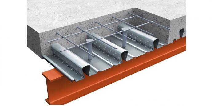
Composite slabs in steel frame construction can assume two forms. The first being the traditional concrete slabs that could either be in-situ or precast units and the other being the metal decking which is more commonly called profile steel decking/sheeting. The latter is more widely used because it offers numerous advantages over the former. Composite slabs with profiled steel sheeting consist of cold-formed thin-walled sheets with embossment on top flange and concrete poured into the steel sheeting (See featured image).
The combination of steel sheeting and concrete in composite slabs offers a range of benefits that have contributed to their widespread use in construction. Firstly, the steel sheet provides structural strength and stiffness, complemented by the compressive strength and fire resistance offered by the concrete. This combination results in a highly durable flooring system suitable for various building projects. Additionally, the speed of construction is significantly enhanced by the profiled steel sheeting, which can serve as formwork and also falsework when unpropped construction is considered. This dual functionality reduces construction time as concrete cures within the sheeting, eliminating the need for additional formwork removal and expediting construction schedules.
In addition, composite slabs prove to be an economical choice compared to traditional reinforced concrete slabs due to reduced material usage and faster construction times. This cost-effectiveness, coupled with the flexibility in design enabled by different steel profiles and a relatively smaller concrete thicknesses, allows for tailored solutions to achieve specific load capacities, spans, and fire ratings. Furthermore, the inherent fire resistance provided by the concrete encasing the steel sheet enhances safety in buildings, addressing concerns regarding fire safety in construction projects.
Design of Composite Slab with Profile Steel Deck
The design of a composite slab is very similar to the design of composite beam. Just like composite beams, a composite slab can also be designed in two ways, either as propped construction in which the resistance of the steel section to carry construction load is not considered or a unpropped construction where both the resistance of the steel section and composite sections must be verified (See: Designing a Composite Beam to Eurocode 4).
Usually, in the design of composite slabs with profile sheerings, the manufacturer gives information on the properties of profiled steel sheeting. These properties are usually based on test results performed in accordance with EN 1993-1-3, Annex A. Characteristic and design values of resistance moment, crushing resistance, second moment of area etc. may be estimated using methods of reliability analysis in accordance with EN 1990. Properties of profiled steel sheeting estimated by calculation are more conservative than equivalent properties based on testing.
Member Verification
The member verification required depends on whether the check is being conducted at the construction stage or composite stage. At the construction stage, the verification is done as if the composite slab were to be a pure steel element, while at the composite stage the checks are carried out with the slab acting as a composite element.
Member Verification at Construction Stage
The following checks are carried out at the construction stage if unpropped construction is utilized:
- Flexure verification according to BS EN 1993-1-1
- Shear verification according to clause 6.1.5 of BS EN 1993-1-1
- Deflection verification
How to carry out this check is covered in a previous article (See: Designing a Laterally Retrained Beam to Eurocode 3)
Member Verification at Composite Stage
At the composite design stage, the following checks are applicable
- Flexure verification according to BS EN 1994-1-1
- Longitudinal shear resistance according to clause 9.7.3 of BS EN 1994-1-1
- Vertical shear resistance according to clause 9.7.5 of BS EN 1994-1-1
- Deflection Verification
Some of the above checks were covered in the last article on: Designing a Composite Beam to Eurocode 4. Longitudinal shear resistance, vertical shear resistance and deflection verification will be expatiated in the worked example in the next section.
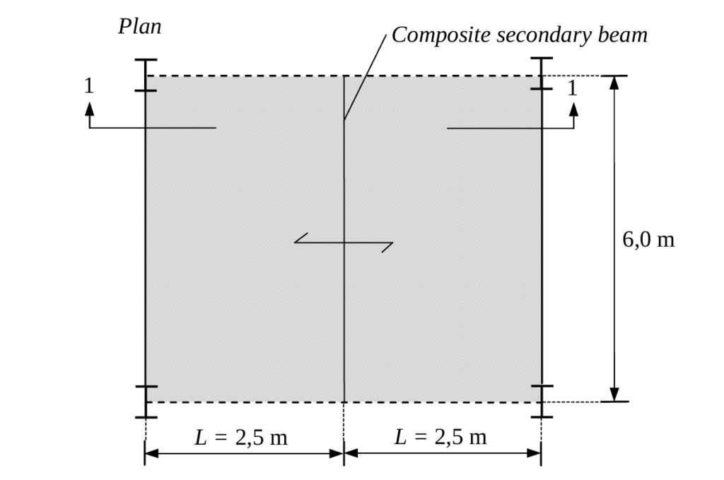
Worked Example
Figure 2 shows the plan of a composite slab in a proposed office building. The composite slab is two span and consist of cold-form profile sheeting covered with a concrete slab. Using the Data provided in Table 1, Carry out all verification required on the composite slab assuming unpropped construction is to be employed. The characteristic permanent and variable actions at the construction stage is 3.3kN/m2 and 1.5kN/m2 respectively and at the composite stage is 4.38kN/m2 and 7.0kN/m2 respectively.
| Concrete Properties | ||
| Concrete | C25/30 | |
| Reinforcement | 500Mpa | |
| Profile Sheeting (from manufacturer) | ||
| t | 1.1mm | |
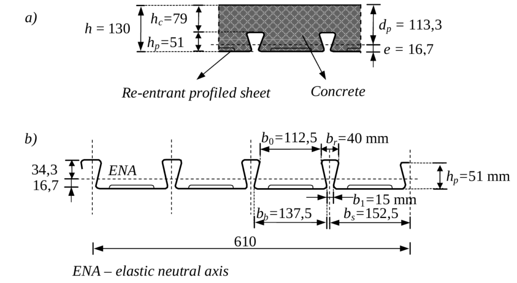
| hp | 51mm | |
| Ape | 1938mm2/m | |
| I | 685000mm4 | |
| E | 210000 | |
| MRd | 7.0kN.m | |
| m | 128.5N/mm2 | |
| k | 0N/mm2 |
Note that we need to consider the construction stage and the composite stage. At the construction stage, the profiled steel sheeting acts as shuttering. The profiled sheeting has to carry its own weight, the wet concrete and the construction loads. In the composite stage, the slab is loaded with its own weight, the floor finishes and the variable load.
The composite slab is almost always continuous, because the profiled sheeting is provided in two-span lengths and the concrete is cast on the sheeting without joints (Figure 2). However, very often it is assumed that it is simply supported. According to clause 9.4.2(5), EN 1994-1-1, the continuous slab may be designed as a series of simply supported spans. In such cases, according to clause 9.8.1, EN 1994-1-1, the reinforcement for crack control is provided above internal supports.
Member Verification at Construction Stage
At the construction stage, it is necessary to carry out verifications of profiled steel sheeting for the ultimate and serviceability limit states in accordance with EN 1993-1-3.
Profiled steel sheeting is continuous over two or more spans. However, in some cases, a single span is unavoidable due to the floor geometry.
Design Value of Actions at Construction Stage
n_{s1}= (1.35\times3.3)+(1.5\times1.5)\\= 6.7kN/m^2The slab can be idealized as simply supported for both the construction stage and composite stage; hence the following equations can be utilized to determine the bending moment and shear forces in the slab.
Bending Moment @ Construction Stage
M_{Ed}=\frac{n_{s1}l^2}{8} = \frac{6.7\times2.5^2}{8}= 5.2kN.mShear Force @ Construction Stage
V_{Ed}=\frac{n_{s1 }l}{2}=\frac{6.7\times2.5}{2} =8.4kNVerification for Flexure
\frac{M_{Ed}}{M_{Rd}}=\frac{5.2}{7.0}=0.75\le1.0By inspection the slab will also satisfy the requirement with respect to shear and deflection, hence these checks will be ignored in this article. However, guidance on how to carry out the full checks can be obtained from any of the referenced texts in the sources & citation section of this article.
Member Verification at Composite Stage
Similarly, the continuous composite slab is designed as a series of simply supported spans, in accordance with clause 9.4.2(5), EN 1994-1-1, provided that the criterion for minimum reinforcement above internal supports of composite slab is satisfied, clause 9.8.1, EN 1994-1-1
n_{s2}= (1.35\times4.38)+(1.5\times7.0)\\= 16.4kN/m^2Therefore, the design bending moment and shear force are as follows:
Bending Moment @ Composite Stage
M_{Ed}=\frac{n_sl^2}{8}=\frac{16.4\times2.5^2}{8} =12.8kN.mShear Force @ Composite Stage
V_{Ed}=\frac{n_{s1 }l}{2}=\frac{16.4\times2.5}{2} =20.5kNVerification for flexure
Recall that for a composite steel section, the bending moment of resistance depends on the location and depth of the neutral axis. Thus, the design compressive force in concrete is given as:
R_{c}=0.85f_{cd}h_cb\\=0.85\times25/1.5\times79\times1000 =1119kNThe design tensile force in the steel sheeting for a width of sheeting b is calculated with the characteristic of the effective steel section Ape
R_s=A_{pe}f_y=350\times1938\times10^{-3}\\=678kNSince Rp < Rc, the plastic neutral axis lies within the concrete. The depth of neutral axis is estimated using the following equation:
x=\frac{R_s}{0.85f_{cd}b}=\frac{678\times1063}{0.85\times\frac{25}{1.5}\times10^3}=47.8mmTherefore, the bending moment resistance is obtained as:
M_{pl,Rd}=R_s (d_p-0.5x) \\=678\times(113.3-0.5\times47.8)\\=60.6kN.mTherefore, since design bending moment is less than the bending moment resistance (12.8 kN.m < 60.6 kN.m), the composite slab satisfies the requirement with respect to the flexural check.
Verification for Longitudinal Shear
Where there is no end anchorage longitudinal shear resistance of the composite slab section must be checked. This is calculated according to clause 9.7.3, EN 1994-1-1. The design resistance of a composite slab against longitudinal shear is carried out by the semi-empirical method called the m-k method. According to clause 9.7.3(4), EN 1994-1-1, the maximum design vertical shear VEd for a width of slab b is limited due to the design longitudinal shear resistance Vl,Rd, given as:
V_{l,Rd}=\frac{bd_p}{\gamma_{vs}}(\frac{mA_p}{bL_s+}+k)Where: b, dp are in mm, Ap is the nominal cross-section of the sheeting in mm2, m, k are design values for the empirical factors in N/mm2 obtained from slab tests meeting the basic requirements of the m-k method, Ls is the shear span in mm, defined in clause 9.7.3(5), EN 1994-1-1, Ys is the partial factor for ultimate limit state; the recommended value is 1.25.
If the m-k method is used, it should be verified that the maximum design vertical shear VEd does not exceed the design shear resistance Vl,Rd:
Design values of empirical factors m and k are based on slab tests and are provided by the manufacturer of the sheeting:
For this worked example, m=128.5 mN/mm2 k =0 N/mm2 (See table 1)
According to clause 9.7.3(5), EN 1994-1-1, the shear span Ls for the uniform load applied to the entire span length is:
L_s =\frac{L}{4} =\frac{2500}{4} =625mmThus, the design longitudinal resistance is given as:
V_{l,Rd}=\frac{10^3 \times133.3}{1.25}(\frac{128.5\times1938}{10^3\times 625}+0)= 36.1kNSince the value of vertical shear in the composite slab (20.5kN) is less than the longitudinal shear resistance value (36.1kN), the composite slab satisfies the requirement.
Verification for Vertical Shear
According to 9.7.5, EN 1994-1-1, the vertical shear resistance, Vv, Rd should be determined according to the method given in EN 1992-1-1. According to clause 6.2.2., EN 1992-1-1, the design shear resistance V
is calculated as:
V_{v,Rd}=0.12k(100\rho f_ck)^{1/3}bd_p \ge0.035k^{2/3}\sqrt f_{ck}bd_pSubstituting the values into the above equation, we obtain Vv,Rd = 73.9kN
Therefore, since value of vertical shear in the composite slab (20.5kN) is less than the vertical shear resistance value (73.9kN), the composite slab also satisfies the requirement.
Deflection Verification
According to clause 9.8.2(4), EN 1994-1-1, calculation of the deflection of the composite slab can be omitted if the two conditions are satisfied. According to the first condition, the span/depth ratio of the slab should not exceed the limits given in EN 1992-1-1. These are:
- L/d <20 for a simply supported span
- L/d<26 for an external span of continuous slab
- L/d<30 for an internal span of continuous slab
The second condition is covered in clause 9.8.2(6), EN 1994-1-1 which provides that: the load causing an end slip of 0.5 mm in the tests on composite slab should not exceeds 1.2 times the design service load for deflection calculation to be omitted.
For the considered slab, with L = 2500 mm and dp =113.33mm, the span/depth ratio is obtained as follows:
\frac{L}{d_p}=\frac{2500}{113.3} =22 <26Therefore, it is not necessary to carry out the calculation of the deflection. However, where calculation is required, the deflection is carried out in the same fashion as done for composite beams.
Control of cracking of concrete
Since the slab is constructed with simple support, reinforcement is necessary to control crack width. In accordance with clause 9.8.1(2) of EN 1994-1-1, for unpropped construction, the prescribed cross-sectional area of reinforcement, denoted as A, amounts to 0.2% of the concrete area above the rib. Thus:
A_s =0.02b(h-h_p)\\=0.02\times10^3\times(130-51)\\=158mm^2/m
Therefore, provide A193 Mesh in Top of Slab
Also See: Floor System in Steel Framed Buildings
Sources & Citations
- Institution of Structural Engineers (2010) Manual for the Design of Structural Steelwork to Eurocode 3.
- Mosley W. H., Hulse R. and Bungay J.H. (2012) Reinforced Concrete Design to Eurocode 2 (7th ed.) Basingstoke, UK: Palgrave MacMillan
- Dujmović / Androić / Lukačević (2015) Composite Structures according to Eurocode 4 – Worked Example. Wiley