This article examines the various types of formworks and falsework needed to construct a concrete bridge and their requirements.

The first and second article in the series on concrete bridges noted that the choice of a bridge type depends not only on the general parameters of the scheme (such as typical spans, overall deck area, clearance requirements, alignment and the overall aesthetic), but also on the particular and local parameters of the site, many of which are related to construction. One of these local parameters relates to formwork and falsework used to construct concrete bridges.
The sixth instalment in the series discusses concrete bridge formwork and falsework In this article, the various types of formworks and falsework needed to construct a concrete bridge are examined.
Formwork Types
In situ bridge deck construction, workers cast and erect the bridge deck simultaneously in its final position. They use formwork, also known as shuttering, to mold the concrete. This formwork is then supported by falsework, typically raised above the ground, until the bridge achieves enough strength to support itself.
For precast construction, the process involves three distinct phases: casting, transportation, and erection. Formwork is once again necessary to shape the concrete. This formwork, or mold, typically rests directly on the ground and thus does not require significant falsework support. Casting can occur either in an existing precast factory or on-site in a precast yard. Once completed, the units are either stored, left in place until needed for transportation, or transported directly to the construction site. When the bridge site is prepared to receive the precast units, they must be transported from storage to the construction site, which may be a considerable distance away. Subsequently, the precast units are erected into their final bridge form, requiring the use of a falsework system.
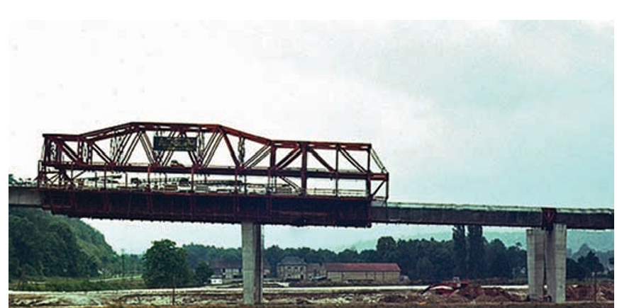
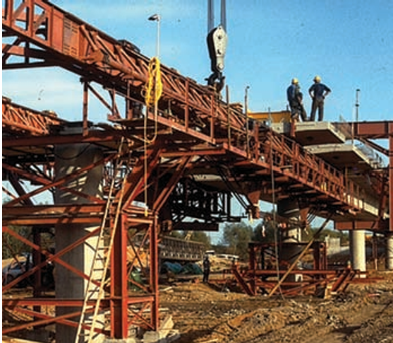
Timber formwork panels, typically ranging from 10 to 40 meters in length, are most suitable for casting short to medium span bridges in situ. These panels commonly use phenolic film-faced plywood as form-face material, which can endure up to 50 uses before requiring refurbishment or replacement. Consequently, timber forms are often employed for in situ casting of solid slab, voided slab, twin rib, or box girder bridges. These forms are supported by scaffold falsework or a network of beams and props. Since they are usually cast span by span, a typical approach involves casting each span along with a short cantilever extending into the next span, typically around 0.2 to 0.25 of the span length. This practice ensures that the as-built moments in the deck closely align with the final moments, thus mitigating the impact of creep. As the deck length grows sufficiently, mechanizing the process becomes cost-effective, often accomplished using a gantry falsework system spanning between piers or from the previously constructed deck to the next pier (Figure 1). For these longer pours spanning 20 to 40 meters, steel formwork is typically employed due to its capacity to accommodate the casting of around 20 to 100 units before requiring refurbishment.
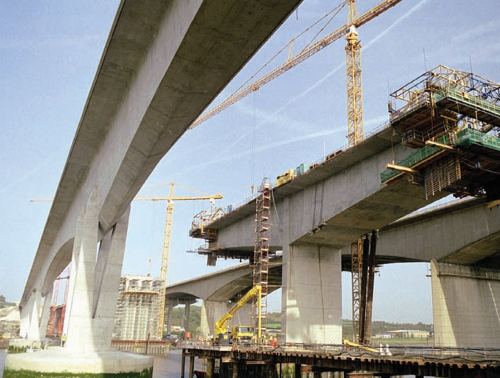
Balanced cantilevering stands as the sole in situ construction method employing short concrete pours, applicable to spans ranging from 40 meters to over 300 meters. This method involves forming the bridge from brief in situ segments, typically 3 to 5 meters long, cast within a traveling formwork system. These systems primarily utilize timber forms, although steel may be utilized based on their longevity (Figure 2).
On the other hand, for precast units, steel formwork is the standard due to its ability to withstand repeated use. Long steel molds, spanning approximately 10 to 50 meters for beams, can cast between 20 and 100 units before requiring refurbishment. Conversely, short steel molds, ranging from 3 to 5 meters for segments, can cast between 50 and 300 units. Consequently, conventional and customized precast beam bridges, along with whole span precast bridges, typically employ long steel molds (Figure 3). Similarly, incrementally launched bridges, which essentially are precast, are also commonly cast using long steel molds. Conversely, precast segmental and modular precast bridges are usually match-cast in short steel molds, a technique involving casting each new segment between a fixed bulkhead and the previously cast segment to ensure precise fitting and alignment.

In the United Kingdom, the design of formwork and falsework should adhere to BS 5975-3 standards, with additional consideration given to The Concrete Society’s Formwork – a guide to good practice
Permanent Formwork
Permanent formwork expedites construction by reducing the reliance on falsework. Significant cost savings can be achieved when the formwork integrates seamlessly into the completed bridge structure. Moreover, permanent formwork finds utility in locations where removing conventional formwork would be challenging, making it particularly advantageous in scenarios requiring extended possession times, such as over live roads or railways.
Precast concrete lattice girder panels, spanning up to 4 meters, offer versatility as they can serve as both permanent and participating elements. Additionally, two types of non-participating permanent formwork are available, each featuring flat or corrugated profiles adaptable to various configurations. Glass fiber reinforced concrete (GRC) panels are commonly utilized as permanent soffit formwork, spanning approximately 1 meter between closely spaced precast concrete beams. Meanwhile, glass fiber reinforced plastic (GRP) panels are also available, boasting spans of up to 4 meters between supports. Properly sealed joints between the panels, achieved through mortar, tape, or sealants, are essential to prevent grout leakage during subsequent concrete pours.
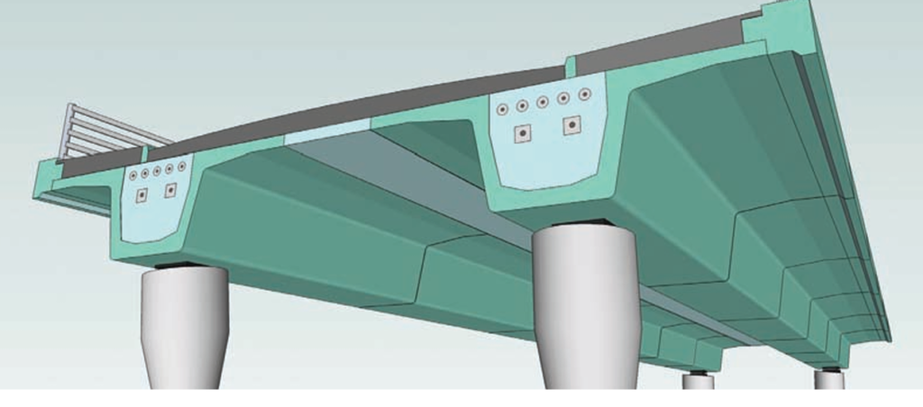
The CBDG developed the modular precast bridge as a permanent formwork system, featuring short precast shell segments that serve as permanent and participating structural formwork for in situ infill concrete (Figure 4). Similarly, precast units can be utilized to shape the exposed face of a wall or column. In such instances, high-quality concrete, such as that incorporating white cement or pigments in the mix, can be employed to achieve the desired appearance, while lower-quality concrete is reserved for the infill material.
Specialist Formwork and Finishes
In addition to employing plywood or steel forms to achieve a high-quality plain concrete finish, it is feasible to create specific shapes or special finishes. Piers are frequently designed to make a significant aesthetic impact, with their shape selected to both complement the load paths and harmonize with the surroundings.
Often, piers are cast using the same formwork, which can be easily supported off the ground, allowing for the creation of intricate pier shapes at minimal additional cost. While abutments and parapet edge beams can also be shaped to some extent, their geometries are typically more restricted compared to piers. Piers, abutment walls, and parapet edge beams can benefit from special finishes applied to the concrete, creating visual cohesion across the entire project. The same finish may be used on some or all of these elements to maintain a consistent theme throughout the scheme. The Concrete Society has produced two comprehensive documents detailing the use of these visual concretes.

Controlled permeability formwork offers the possibility to enhance the density and reduce the porosity of the concrete cover zone. This system utilizes thermally bonded permeable liners consisting of filter and drain elements, affixed in tension to the internal face of the formwork. During the concreting process, entrapped air and excess water in the mix, which might otherwise cause surface blemishes, are allowed to pass through the liner. As a result, the liner creates a uniform surface and a concrete cover zone with significantly enhanced durability (Figure 5).
Falsework Types
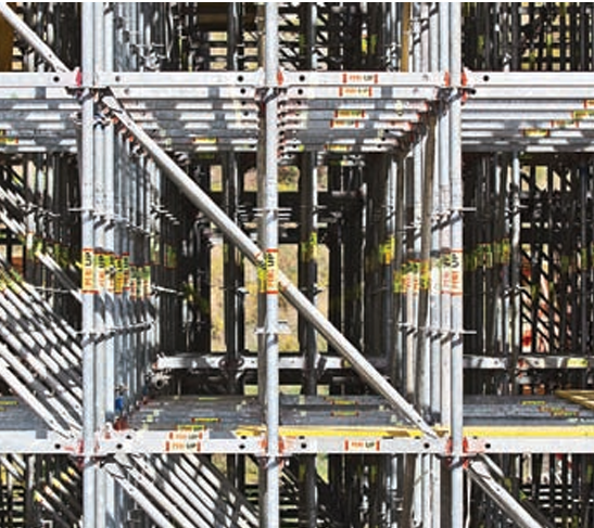
In situ solid slab, voided slab, twin rib, or box girder bridges often rely on falsework for support. This falsework typically consists of a scaffold birdcage (Figure 6) with a sturdy foundation or a series of beams, girders, and props or towers that move from span to span as construction progresses. As the deck length increases, it becomes cost-effective to automate this process using a gantry falsework system, spanning from pier to pier or from the previously constructed deck to the next pier. These gantries can be constructed from off-the-shelf equipment or purpose-built steelwork, advancing themselves as construction proceeds. Depending on clearance and operational considerations, these gantries may be positioned either above or below the deck, with detailed discussions on these issues planned for later in this series.
Individual traveling frames can also be utilized to cast in situ elements using the balanced cantilever method. In this approach, the bridge is formed from short in situ segments, each 3 to 5 meters long, cast in a traveling formwork system supported by the falsework frames. All of this equipment integrates formwork and falsework into a single mechanized unit. It is imperative to operate these machines with safety, speed, and ease of handling in mind throughout each cycle of striking the formwork and falsework, advancing it, and accurately repositioning it for the next in situ concrete pour.
Transportation of major items primarily pertains to various precast options, involving the movement of units from the casting to the erection area. This process utilizes low-loaders, straddle-carriers, wheeled-bogies, or rail systems, comprising both proprietary vehicles and purpose-made equipment.
The erection of precast elements requires cranes and/or various falsework to support the precast units. Standard (and some bespoke) precast beams, weighing between 5 and 80 tons, are lifted using mobile or tracked cranes ranging from 100 to 800 tons, either singly or in tandem formation. Heavier beams (weighing 80 to 120 tons) necessitate the use of larger 1,200-ton cranes, increasingly common in many developed countries. Crane positions must be prepared to accommodate outrigger loads, and ground improvement may be necessary in poor conditions.
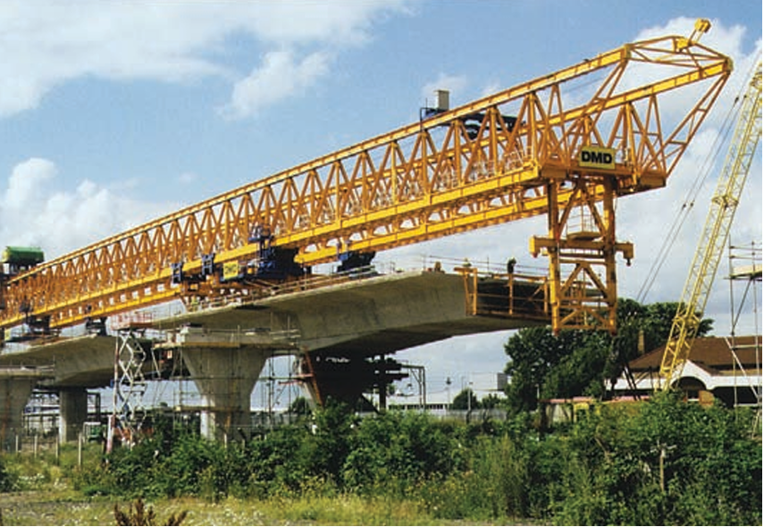
Precast segmental and modular precast schemes, with segments weighing between 25 and 100 tons, can also be erected by crane, provided a firm foundation exists throughout the critical areas of the site. These precast segments can be joined together in their final position, either span by span (supported on an under-slung gantry, Figure 7) or through balanced cantilever construction, stabilized with falsework towers.
Heavier bespoke precast beams (weighing 100 to 200 tons) are typically erected using gantries. These gantries lift the beam from the ground or completed deck, moving it forward and sideways to lower it into position. Gantries span from pier to pier and are usually equipped with front noses and rear tails to facilitate forward movement to the next pier. Gantries for whole span precast units (each weighing up to 1,000 tons or more) follow a similar format but are larger to accommodate the heavier units. For long marine viaducts employing whole span pre-casting, massive marine shear legs are commonly used to lift the entire span, capable of lifting several thousand tonnes.
In precast segmental construction, where crane access is limited, segments can be erected in balanced cantilever with shear legs or lifting frames at each end. Stability of the balanced cantilever is ensured with falsework towers. Once the total deck area exceeds approximately 20,000m2, gantries can be utilized to erect segments span by span or in balanced cantilever, providing stability where needed (Figure 8). These gantries must operate quickly, easily, and safely. Depending on the project scale, operations may be aided by jacking systems, winches, or hydraulics, necessitating corresponding increases in control systems complexity for successful management.
Incrementally launched bridge decks utilize various falsework items such as slide tracks, launching bearings and noses, as well as jacks to facilitate movement. Modular precast schemes, using short shell segments filled with in situ concrete into 20-40m lengths, can also be launched into place similarly.
Stability of the bridge and all its falsework during lifting, moving, and sliding operations is crucial, often requiring additional temporary works to ensure stability in all directions. Temporary prestressing bars are commonly used to clamp concrete elements together or to clamp falsework items to the concrete, providing a safe, quick, and easy method of generating stability. These prestressing bars typically range from 26.5 to 40mm in diameter, with either fine or coarse threads. Coarse-threaded bars are particularly useful on-site as they can be installed, stressed, and reused multiple times, providing constant force even under variable tension loads
Summary
It’s fundamental to understand how the formwork and falsework differ for each construction method when selecting the optimal bridge deck for a specific site. Additional insights into these aspects are provided in the sources and citation section of this article. As highlighted in the previous articles, pricing details would always be required to elucidate the program and costs associated with various concrete bridge options, enabling informed decisions at an early stage of the design process.
See: Management and Maintenance of Concrete Bridges
Sources & Citations
- The Concrete Society (2014) Checklist for assembly, use and striking of formwork, Camberley, UK: The Concrete Society
- Concrete Bridge Development Group (2014) ‘Concrete Bridge Design and Construction series No. 5: Concrete Bridge Formwork & Falsework’, The Structural Engineer, 92 (5), pp. 42–46