This article explores and provides guidance on the structural design and construction consideration in the design of post-tensioned slab to Eurocode 2

Unlike traditional reinforced concrete slabs, which rely solely on the strength of the concrete and embedded steel reinforcement bars, post-tensioned slabs incorporate high-strength steel tendons that are tensioned after the concrete has cured. This innovative approach enables engineers to optimize floor structural performance, increase spans, reduce material usage, and enhance durability.
Post-tensioned (PT) concrete floors have gained extensive usage, especially in high-rise constructions. PT flat slabs offer the slimmest structural choice readily accessible for spans exceeding 7m, and economically support spans up to 13m × 13m. In cases of longer spans, the common approach involves employing a one-way spanning slab supported by band beams.
Typically, PT floors are devised by specialized designers within a performance specification procurement method. Nonetheless, the design itself doesn’t inherently entail complexity, and it’s essential for the primary designer to possess an understanding of PT design advantages and constraints. This facilitates the consideration of a reasonable scheme design as a structural choice in tender documentation. Furthermore, it enables the designer to integrate the design and its benefits into the overall stability and robustness of the structure.
This article offers insights into the process of designing a PT slab and the implications of post-tensioning on the overall structure. For a more comprehensive understanding of PT floor design, Concrete Society Technical Report 43 (TR43), titled “post-tensioned concrete floors: Design handbook,” provides detailed guidance. This handbook is applicable for designing PT floors according to Eurocode 2 and is recognized as non-contradictory complementary information (NCCI) in the UK National Annex.
Bonded and Unbonded Systems
There exist two post-tensioning systems accessible to PT element designers: bonded and unbonded (refer to Figure 1). In the UK, the predominant post-tensioning system is bonded, constituting approximately 90% of the market.
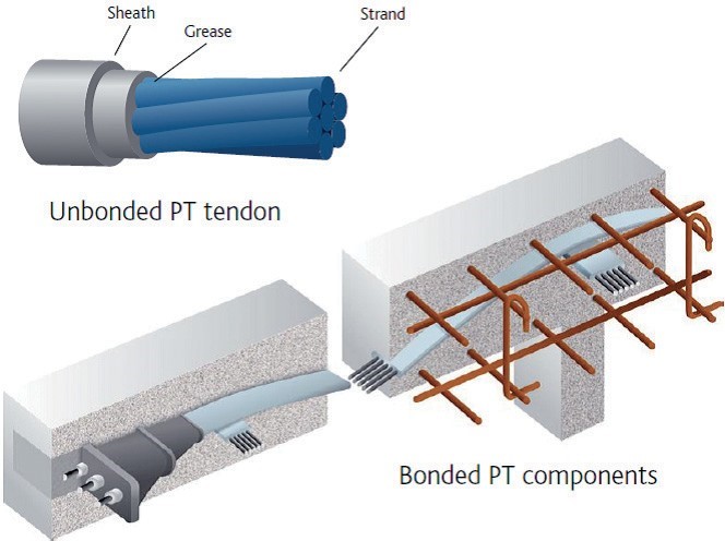
Bonded systems involve prestressing tendons passing through a duct, which is subsequently filled with grout after applying prestress. These ducts can come in circular or flat shapes and can accommodate multiple tendons. The advantage of using a bonded system lies in the fact that once the grouting has set, the anchorages become inactive. Consequently, any damage to a tendon, such as if it’s cut through by a post-drilled fixing, is confined to the bond length of the tendon on both sides of the cut. Moreover, the grout provides protection against corrosion for the tendon, similar to how normal reinforcement is shielded in reinforced concrete structures. Lastly, bonded systems are as straightforward to dismantle as regular reinforced concrete, or perhaps even slightly easier due to the lesser amount of reinforcement within the structure.
Both bonded and unbonded systems can be employed in the same slab if the design necessitates it. Table 1 provides a comparison between the two systems.
Restraint
During the concept phases of a design that utilizes post-tensioned slabs, careful attention must be given to avoiding restraint issues. Restraint occurs when the free movement of the slab length under prestress forces is hindered, such as by the unfavorable positioning of shear walls or lift cores (see Figure 2).
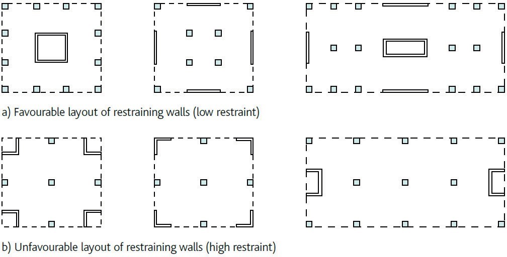
All concrete elements undergo shrinkage due to drying and early thermal effects. Additionally, prestressing induces elastic shortening and ongoing shrinkage due to creep. Rigid vertical members like stability walls restrict the floor slab from shrinking, thereby impeding prestress development and reducing the floor’s strength.
In scenarios where the restraining walls are favorably arranged and the floor is within an internal environment, the length of the floor without movement joints can extend up to 50m. Nevertheless, comprehensive consideration must be given to the effects of shrinkage due to drying, early thermal effects, elastic shortening, and creep during the design process. A strain of 650με should be deemed normal.
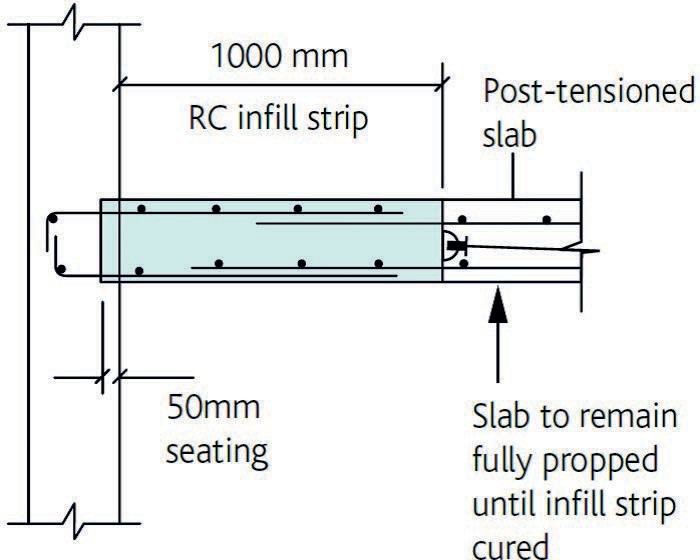
When walls are unfavorably arranged, an assessment of movement effects should be conducted, and appropriate measures should be implemented to address them. This may involve:
Incorporating infill strips, also referred to as pour strips, typically cast around 28 days after the remainder of the floor to allow initial shrinkage to occur (refer to Figure 3).
- Augmenting the quantity of conventional reinforcement to regulate cracking.
- Employing temporary release details.
- Utilizing proprietary temporary release details.
- Diminishing the stiffness of restraining elements.
Additionally, the impact of floor shortening on the columns should be factored into their design, as this may amplify the design moments.
Materials and Specifications
PT slabs typically do not necessitate the use of exceptionally high-strength concrete, with class C32/40 often employed in standard flat slab designs. For expeditious construction, the concrete should possess high early strength. This facilitates early prestressing, typically performed within 24 hours, to mitigate cracking. Final prestressing can occur after three days, once the concrete attains a predetermined strength, enabling formwork removal. While higher levels of cement replacements like ground-granulated blast-furnace slag (GGBS) or fly ash can be utilized, they may extend the construction timeline and potentially alter design parameters, such as strains induced by creep and early age shrinkage.
Table 2 outlines the common strand types utilized in the UK, with a recommendation to use only one type per project. A specification detailing the execution of PT floors can be found in the National Structural Concrete Specification, section 7.
Overview of Design Process
Figure 4 shows a flow chart for designing PT slabs. Eurocode 2 provides recommendations for prestressed concrete design. Design methods for PT flat slabs are relatively simple, and TR43 offers detailed guidance based on Eurocode 2.
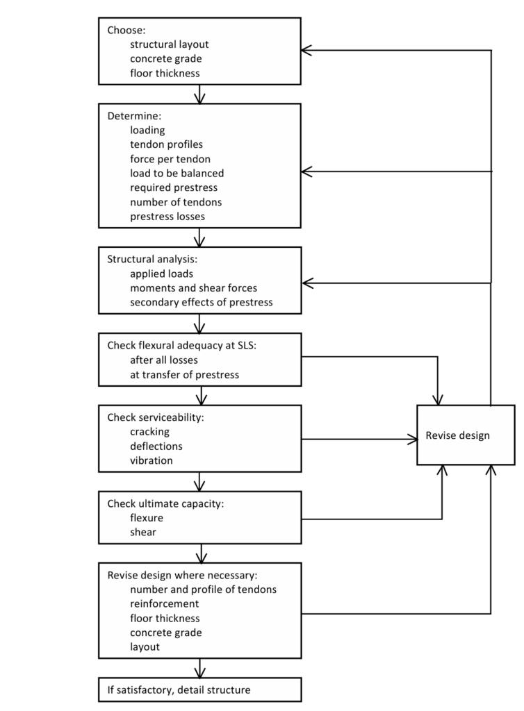
At the serviceability condition, check the concrete section at all positions to ensure compressive and tensile stresses are within Eurocode 2 limits. Examine stresses in the concrete section at the initial condition when applying prestress and at serviceability conditions to determine deflections and crack widths for various load combinations.
At the ULS, ignore pre-compression in the section and ensure it has sufficient moment capacity. Also, check shear stresses at the ULS similarly to reinforced concrete design, while considering the benefit of the prestress across the shear plane.
At the serviceability limit state (SLS), a prestressed slab is usually in compression, making flexural cracking rare. This allows for accurate deflection predictions since the properties of the uncracked concrete section are easily determined. Estimate deflections and limit them to specific values rather than controlling the span-to-depth ratio as in reinforced concrete design.
Use computer software extensively to provide accurate structural models, account for the effects of other elements, apply different load combinations, and perform both structural analysis and prestress design. Understand the basic principles of prestressed concrete design by considering the stress distribution in a concrete section under external forces or loads. Figure 5 illustrates the basic theory’s simplicity.
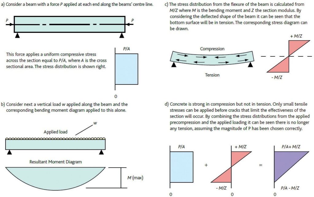
For serviceability design, check the stress distribution under the combined action of prestress and applied loads at all positions along the beam to ensure both compressive and tensile stress remain within design standards limits. Design PT beams and slabs to maximize the continuity benefits provided by adjacent spans, considering secondary effects that can refine a design.
Most prestressed slabs require additional reinforcement to control cracking or supplement tendon capacity at ultimate load conditions. The load-balancing technique is a powerful tool for designers, modeling forces exerted by prestressing tendons in a catenary as equivalent upward forces on the slab. Proportion these forces to balance the applied downward forces (Figure 6), allowing control over deflections and efficient use of slab depth.

To use the load-balancing technique, set prestressing tendons to follow profiles reflecting the bending moment envelope from applied loadings, typically using parabolic profiles. In PT concrete floors, this technique enables the optimum depth for any given span. The slab’s final thickness, as with reinforced concrete flat slabs, may also be controlled by punching shear around the column.
For a parabolic profile, the upward uniformly distributed load
w=\frac{8Pa}{s^2}where: s is the span, 𝑎 is the drape, and is the prestress force.
This upward load usually balances the self-weight and superimposed dead load and can sometimes balance some live loads, depending on the design. Extend this to several spans for a more economical design as the drape is larger (Figure 7). Place anchorages at the section’s centroid to prevent moments at the beam or slab ends.

Initial sizing of PT slabs
PT slabs can initially be sized using span- to-depth ratios. TR43 and the Concrete Centre book, Economic Concrete Frame Elements to Eurocode 2, provide these ratios for various slab types. Table 3 outlines the typical span ranges used for PT floors.
Prestress losses
From the moment a post-tensioning tendon is stressed to its final state many years later, various losses occur that reduce the tension in the tendon. These losses fall into two categories: short-term and long-term losses.
Short-term losses
Short-term losses occur during the stressing and anchoring of the tendon and include:
- Friction losses in the tendon
- Wedge set or ‘draw-in’
- Elastic shortening of the structure
Long-term losses
Long-term losses occur over a period of 10 or more years, with the majority happening in the first two years after stressing. These losses include:
- Shrinkage of the concrete
- Creep of the concrete, including the effect of the prestress
- Relaxation of the steel tendon
The reduction in prestress force after stressing can be substantial, ranging from 10% to 50% of the initial jacking force at transfer and from 20% to 60% after all losses. Therefore, it is essential to calculate these losses in all instances. TR43 provides guidance on prestress losses in Appendix B.
Conclusion
This article does not fully explain the design of PT floors. Designers should familiarize themselves with TR43 at the beginning of the design process. The design of PT floors allows for flexibility in adjusting various aspects—such as prestress force and tendon profile—to achieve the most economical design. Numerous software packages, including 2D design tools and finite-element analysis programs, can assist in this process.
The Post-Tensioning Association (PTA) in the UK also offers valuable support. It provides technical design guidance and is developing a model performance specification for PT floors. This specification aims to help main designers understand the requirements of specialist designers and what they can expect from these specialists and contractors. For more information, visit the PTA website at www.posttensioning.co.uk.
Also see: Concrete Slabs in Concrete Frame Buildings
Sources & Citation
- The Concrete Society (2005) Technical Report No. 43: Post- tensioned concrete floors: Design handbook (2nd ed.), Camberley, UK: The Concrete Centre
- Goodchild C. H., Webster R. M. and Elliott K. S. (2009) Economic Concrete Frame Elements to Eurocode 2, Camberley, UK: The Concrete Centre
- Institution of Structural Engineers (2015) Design of Post-tensioned Slabs. Concrete Design Guide, The Structural Engineer.