This article highlights the advantages of composite beams over normal steel beams and guidance for designing composite beams to Eurocode 4.
Steel frameworks typically consist of steel beams and columns, often paired with a concrete floor slab. Achieving a significantly stiffer and stronger structure can be achieved by ensuring that steel beams and concrete slabs work together as composite units. This composite behavior is ensured by establishing shear connections at the interface between the steel beam and the concrete slab (Figure 1). These connections effectively counteract horizontal shear and prevent slippage between the beam and the slab. Typically, shear connectors take the form of steel studs welded to the top flange of the beam and embedded in the concrete slab.
Composite steel beams offer several advantages over normal steel beams. Firstly, combining steel beams with a concrete slab acting together as a composite unit, enhances the strength and stiffness of the structure. For example, the moment of resistance of the same UB-section is significantly higher when it is designed as a composite beam than when it is designed as a normal beam.
Secondly, composite steel beams tend to exhibit lower deflection under load compared to traditional steel beams. The combination of steel and concrete results in a stiffer section, which in turn leads to reduced deflection and improved serviceability of the structure.
The third advantage of composite steel beams is their versatility in design. Alternative beam configurations, such as castellated beams or lattice girders, offer options for optimizing floor space and integrating service conduits. While initial construction costs may be slightly higher due to the additional materials and labor required for composite construction, the long-term benefits often outweigh the initial investment. The increased strength and durability of composite steel beams can result in cost savings over the life cycle of the structure, including reduced maintenance and repair expenses.
Design of Composite Steel Beams
There are two methods by which composite beams can be designed based on the construction method. The designer of any composite steel structure must consider this requirement before the design is carried out. Construction methods can either be propped or unpropped.
In propped construction, temporary props support the steel beam during floor construction, carrying all construction loads until the concrete sets. However, this method results in a lack of clear space under the floor during construction and longer construction times, increasing costs. While in unpropped construction the steel beam supports construction loads, influencing beam size. Thus, only when the concrete in the slab has hardened can the beam act as a composite section. It’s crucial to establish the construction method at the outset due to differences in design procedures for these approaches.
Where propped construction is selected in the design of a composite beam, the steel section principally sized as a composite beam. Whereas if unpropped construction is selected, the implication is that the steel section must sized in two ways – first as a normal steel beam supporting construction loads, secondly as a composite beam supporting the actual design load.
The design of normal steel beams has been covered in previous articles See (Designing a Laterally Restrained Steet Beam & Designing a Laterally Unrestrained Steel Beams). Hence this article would seem to focus only on propped construction. However, when the composite beam is to be designed using unpropped construction, the only difference has aforesaid is that in addition to the checks listed in this article, the beam section must be designed as a normal steel beam using the wet density of concrete to estimate load and a construction load of 0.75kN/m2 is considered as the imposed load over the floor area.
Steps in Designing a Composite Beam
The following steps is followed in the design of a composite steel beam
- Determine the construction method to be followed – propped construction or unpropped construction
- Determine the loads at the composite stage only if propped construction is selected otherwise determine the loads for both construction stage and composite stage
- If propped construction has been selected proceed to next step, otherwise verify the beam as a normal steel beam supporting the construction load before proceeding to the next step.
- Determine the moment & shear resistance of the composite beam and compare with the design bending moment and shear force derived using the composite stage loads
- Verify that deflection of the steel beam is within limit.
Member Verification
Three checks are basically required to size a composite beam based on Eurocode 4 – moment resistance, shear resistance and deflection check. This is briefly described in the following sections
Flexural Resistance
According to BS EN 1994-1, provided a section is class 1 or 2, the design bending resistance of the composite beam may be calculated using rigid plastic theory where the tensile strength of the concrete is neglected. Any profiled sheeting in compression is also ignored.
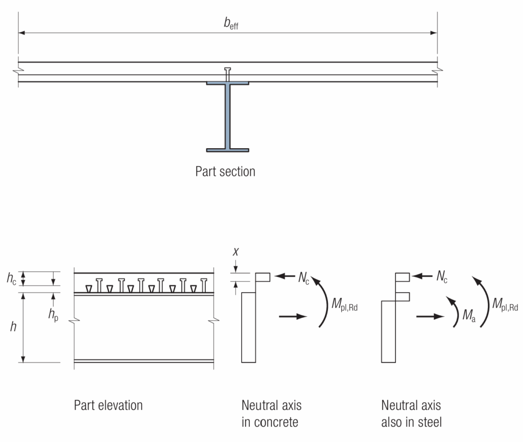
Figure 3 shows possible stress distributions in the concrete and steel. The bending resistance of a beam needs to be checked at critical sections, these are the point of maximum moment and sections subject to concentrated loads. Where the moment resistance of the composite beam is more than 2.5 times that of the non-composite steel beam, the composite beam should also be checked midway between any critical sections and between critical sections and the supports.
The design bending moment resistance of a composite beam can be calculated by following the following procedures.
To determine the bending moment resistance of a composite depends on the position of the neutral axis. Three scenarios are possible. These are:
- The neutral axis in the concrete flange
- The neutral axis in the steel flange.
- The neutral axis in the steel web.
The following steps can be followed in trying to estimate the flexural resistance.
Step 1: Determine the value of Nc, which is the force in the concrete and taken as the minimum of Rc, Npl,a
Where: Rc is the axial resistance of the concrete and Npl,a is the axial resistance of the steel section given as follows respectively.
R_c=0.85f_{cd}b_{eff}h_cN_{pl,a}=\frac{Af_y}{\gamma_{M0}}If Rc > Npl,a then neutral axis is in the concrete section, otherwise it is in the steel section
Step 2: Determine the location of the neutral axis by estimating the value of x as follows:
x=\frac{N_c}{0.85f_{cd}b_{eff}}Where: Nc is as defined in step 1; fcd is the design strength of concrete and beff is the effective width of the composite beam, taken as minimum of (1) one eight of the spans of the beam, (2) half the distance to any adjacent parallel beam (3) when adjacent to an edge parallel to the beam, the distance to the edge of
the slab.
Step 3: Determine the bending moment resistance of the composite steel beam based on the location of the neutral axis:
If Rc >= Npl,a then the bending moment resistance is calculated as follows:
M_{pl,Rd}= R_c(0.5h+h_p-0.5x)Whereas if If Nc < Npl,a then the bending moment resistance is calculated as follows:
M_{pl,Rd}= R_c(0.5h+h_p-0.5x)+M_aWhere Ma is the plastic moment resistance of the steel section reduced to account for the presence of the axial tension. Conservatively it may be taken as My,Rd i.e. the full plastic moment resistance of the steel section about the y-y (major) axis
Shear Resistance
The shear resistance at the composite design stage is estimated in the same way as for a normal steel beam, considering only the steel section. See article on designing a laterally restrained steel beam.
Deflection Verification
Deflection verification in composite beam is very similar to how it is done for normal steel beam, except in this case, the total section must be transformed into an equivalent steel section first and the normal deflection equation can be utilized to estimate vertical deflection of the composite beam.
Vertical deflection limits for steel beams are also valid for composite steel beams and can be found in the Clause NA.2.23 of the UK National Annexe to BS EN 1993-1-1. The list below is based on these stated limits, which are for the deflection due to unfactored imposed loads/variable actions only
- L/360 for steel beams supporting brittle finishes
- L/200 for steel beams not supporting brittle finishes
- L/180 for cantilevers.
Worked Example
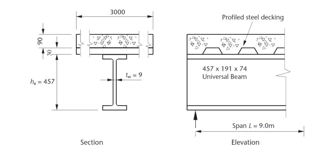
Figure 2 section and elevation of a composite beam of a propped composite floor construction in an office building. The flooring consists of 140mm profile steel decks with composite steel beams spaced at 3.0 centres. Check the adequacy of a universal 457x 191x 74 kg/m steel beam. The steel is grade S355 with fy 355 N/mm2 and the plastic modulus for the steel section is Wpl,y 1653 cm3. The transformed second moment area of the cross-section is Ia=1019 x 106mm3. The characteristic permanent and variable actions at the composite stage is 5kN/m2 and 3.0kN/m2 respectively. Use C25/30 Concrete
Since the composite floor construction is propped, we need not consider construction stage, the composite beam will be design for the composite design stage only.
Actions
Design Value of Actions
n_s=1.35g_k+1.5q_k
n_s=(1.35\times5)+(1.5\times3)=11.25kN/m^2
Since beam is spaced at 3.0m centres, total load transferred from composite slab to beams can be estimated as:
w=11.25\times3.0=33.75kN/m
Structural Analysis
Since the beams are simply supported, therefore, the bending moment and shear force is obtained as follows:
Bending Moment
M_{Ed}=\frac{wl^2}{8}=\frac{33.75\times9^2}{8}= 342kN.mShear Force
V_{Ed}=\frac{wl}{2}=\frac{33.75\times9}{2}=152kNMember Verification
Flexural Design
Verify \quad \frac{M_{Ed}} {M_{pl,Rd}} \le1.0Flexural Resistance
To determine the flexural resistance, we must determine the location of the neutral axis by following the steps outlined in the article.
Step 1: Determine the force in the concrete taken as Rc
R_c=0.85f_{cd}b_{eff}h_c=0.85\times \frac{25}{1.5}\times3000\times(120-30)\\=3827.3kNStep 2: Determine the force in the steel section
R_s =\frac{Af_y}{\gamma_{M0}}=\frac{9460\times355}{1.0}\\=3358kNSince Rc > Rs therefore the neutral axis is in the concrete section.
Step 3: Determine position of neutral axis
x=\frac{R_c}{0.85f_{cd}b_{eff}}=\frac{3358\times10^3}{0.85\times \frac{25}{1.5}\times 3000}]\\=79.0mmTherefore, the moment of resistance of the section is given as:
M_{pl,Rd}= R_s(0.5h+h_p-0.5x)3358\times(0.5\times457+(120-30)-0.5\times79)\\= 1105kN.m
=\frac{342}{1105}= 0.3<1.0Shear Design
Verify\quad \frac { { V }_{ Ed } }{ { V }_{ c,Rd } } \le 1.0Shear Resistance
{ V }_{ c,Rd }=\frac { { A }_{ v }\left( { f }_{ y }/\sqrt { 3 } \right) }{ { \gamma }_{ M0 } }{ A }_{ v }=dt_w=407.6\times9.0=3668mm^2V_{c.Rd}==\frac { 3668\left( 355/\sqrt { 3 } \right) }{1.0} =751kN\frac{152}{751}=0.2<1.0Deflection Verification
Since the composite floor construction is propped, it follows that no deflection will happen during the construction stage. Therefore, deflection is estimated for the service only, using the total permanent action and quasi permanent component of the variable action. For simplicity, the characteristics actions presented in the worked example is used to verify deflection here.
Characteristics permanent actions
w_g=5\times 3.0 =15kN/m
Characteristics variable actions
w_q=3\times3=9kN/m
Since the composite beam is simply supported and carries a uniformly distributed loading, the maximum deflection occurs at midspan, and it is given as:
\delta_{a}=w_g+w_q\frac{5L^4}{384E_aI_a}=(15+9)\frac{5\times9^4}{384\times210\times1019}=8.88mm\delta_{lim}=\frac{L}{360}=\frac{9000}{360}=25mmSince the bending, shear and deflection criteria has all been met, the UB section can be adopted for the composite floor construction.
Also See: Steel Columns in Simple Construction
Sources & Citations
- Institution of Structural Engineers (2010) Manual for the Design of Structural Steelwork to Eurocode 3.
- Mosley W. H., Hulse R. and Bungay J.H. (2012) Reinforced Concrete Design to Eurocode 2 (7th ed.) Basingstoke, UK: Palgrave MacMillan