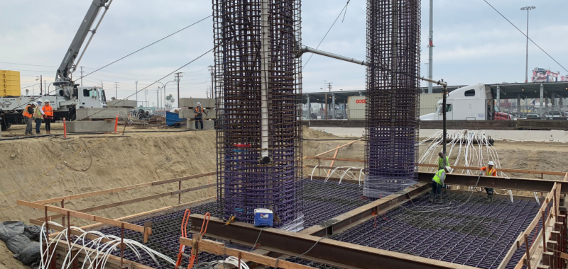
In many instances, a pile cap will be required to sustain loads from two or more columns just like in combined spread foundation. The justification for combining loads from two or more super-structural element typically stems from restrictions. For instance, where the columns are closely spaced such that independent pile caps are impossible to construct as a result of overlapping. Or due to property line restrictions, i.e., where columns are so close to a property line, and the extent of their foundation must not project beyond the property line. Constructing a single pile cap ensures that loads are well distributed into the piles and the restrictions are respected.
Recall, that for simplicity, the location of piles with reference to the point of axial force application should be symmetrical. Thus, in a combined pile-cap, the cap must be proportioned such that the resultant of the applied loads goes through the centroid of the cap. This ensures that load distribution on the pile group is uniform and there is no resultant bending moment on the cap, arising as a result of eccentricity. Where the cap is, however, constraint in any direction, the eccentricities can be determined and considered in the analysis in the design.
Note that this article only extends to the design of pile caps with small pile groups, say 2-4 piles that are purely axially loaded. Those with larger pile groups are outside the scope of this note due to the complexity in their analysis and design.
Designing a Combined Pile Cap
The rules that govern the design of isolated pile gaps also applied for combined pile caps. The layout of the pile group must be determined on the basis of the magnitude of the actions expected from the supported columns. The location of piles with reference to the point of application of the resultant action should be symmetrical. Proximity of piles to one another should at least be 3 times the pile diameter.
See: Design of Pile Caps to Eurocode
Procedure for Design
- Determining the size of the pile and pile cap using the geotechnical data
- Proportion the cap by determining the point of application of the column loads and adjust the pile cap to ensure that the point of application of the column loads coincides with the centroid of the cap.
- Analyze the pile cap for bending moment and shear force by idealizing it as a beam supported on the pile group.
- Design the bending reinforcement in the longitudinal and transverse directions.
- Verify shear and punching shear at the critical sections.
- Verify detailing requirement.
Worked Example
A 300×225 concrete column carrying a design axial design action of 825kN is 1.5 away from 225 x 225 column carrying a design axial action of 275kN. Assuming two 600 piles is sufficient to support the loads, design a combined pile-cap for the columns using C25/30 concrete and 460Mpa reinforcement bars.
Geometry of the pile-cap
Try an overall depth h=1000mm with an average effective depth of 900mm, the spacing between piles = 3×600=1800mm and assuming an overhang of 600mm both ways. width of pile cap = 600+1800+600 = 3000mm. Figure 4 shows the trial geometry of the pile cap.
Proportion the cap
Take moment about the centerline of the 225 x 225 column.
(275+825)\times e =325\times 1.5
e= \frac {825 \times 1.5}{(275+825)} =1.125m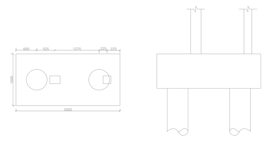
Structural Analysis
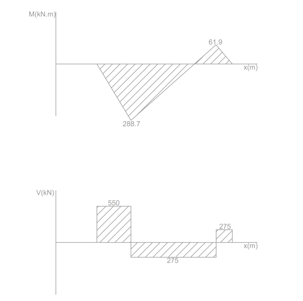
The pile cap is idealized as a beam simply supported on the piles and subjected to point actions from the columns. If we analyze the arrangement, the following bending moment and shear-force diagrams is obtained. Note that for sake of simplicity the weight of the cap itself have been ignored in the analysis.
Flexural Design
Bottom
M_{Ed} = 288.7kN.mk=\frac { { M }_{ Ed } }{ b{ d }^{ 2 }{ f }_{ ck } } =\frac { 288.7\times { 10 }^{ 6 } }{ { 10 }^{ 3 }\times { 900 }^{ 2 }\times 20 } =0.018=0.95d=0.95\times 900=855mm
{ A }_{ s }=\frac { M_{Ed} }{ 0.87{ f }_{ yk } z} =\frac { 288.7\times { 10 }^{ 6 } }{ 0.87\times 460\times 855 } \\=843.7{ mm }^{ 2 }The area of reinforcement required in both direction is given as:
{ A }_{ s,req }=2\times 843.7=1687.4{ mm }^{ 2 }\\ Try\quad T16 @100c/c\quad (2010{ mm }^{ 2 }/m)\\ Verify Minimum Area of Steel
{ A }_{ smin }=0.26\frac { { f }_{ ctm } }{ { f }_{ yk } } bd\quad \ge \quad 0.0013bd\\ { f }_{ ctm }=0.3\times { 30 }^{ 2/3 }\quad =2.9mpa\\ \qquad =0.26\cdot \frac { 2.9 }{ 460 } \times 1000\times 900\ge \\ \qquad =0.0013\times 2300\times 900\\ \qquad =1475.2{ mm }^{ 2 }<{ A }_{ s,pro }\\ Top
M_{Ed} = 61.8kN.mBy inspection, moment in the top zone of the pile cap is minimum, hence area of steel can be provided based on minimum area of steel.
Try\quad T16 @100c/c\quad (2010{mm}^{2})Shear Verification
V =550kN
{ a }_{ v }=\frac { 3000}{ 2 } -600-\frac { 600 }{ 2 } +\frac { 600 }{ 5 } =480mm{ V }_{ ED }=550\frac { { a }_{ v } }{ 2d } =550\frac { 480 }{ 2\times 900 } =146.7kN { V }_{ RD,c }=0.12k(100\rho { f }_{ ck })^{ 1/3 }bd\\\ge 0.035{ k }^{ 3/2 }\sqrt { { f }_{ ck } } bd k=1+\sqrt { \frac { 200 }{ d } } =1+\sqrt { \frac { 200 }{ 900 } }\\ =1.47<2 \rho =\frac { { A }_{ s } }{ bd } =\frac { 2010 }{ 1000\times 900 } =2.23\times { 10 }^{ -3 }{ V }_{ RD,c }=0.12\cdot 1.47( 0.23\times 20)^{ 1/3 } bd\\\ge \\ 0.035\times 1.47^{ 2/3 }\cdot \sqrt { 20}\times bd\quad \quad =264kN(\ge { V }_{ ED }=146.7kN)Punching Verification
Since pile spacing has been taking at exactly 3times the pile diameter, no punching verification is necessary, except at the column face. Punching is verified at the face of the 300 x 225 column only.
{ N }_{ ED }<{ V }_{ RD,max }{ V }_{ RD,max }=0.2\left( 1-\frac { { f }_{ ck } }{ 250 } \right) { f }_{ ck }pd\\ 0.2\left( 1-\frac { 25 }{ 250 } \right) 25\times (1050)\cdot 900=4253kN\quad (>{ N }_{ ED }=825kN)Design Resume
Use Y16 – 100mm Top & Bottom Both-ways.
Further Reading & References
- Mosley W. H., Hulse R. and Bungay J.H. (2012) Reinforced Concrete Design to Eurocode 2 (7th ed.) Basingstoke, UK: Palgrave MacMillan
- The Institution of Structural Engineers (2013). Designing a Pile Cap. Technical guidance notes (level 2).