This fourth article in the series on concrete bridges examines the special types of concrete bridge — previous articles described all the cast in place and precast options, Concrete cable-stayed, extradosed and stressed ribbon bridges are all described here, together with the special features of concrete footbridges and railway bridges.
In the last two articles on concrete bridge, attempts have been made to discuss and classify concrete bridges with regards to construction methodology – ‘cast in place’ and ‘precast’ solutions. The reader will recall that cast in place bridges are those in which in the concrete for the bridge structure is poured and cured on-site in it finished position. Precast bridges on the other hand uses prefabrication techniques. The concrete is poured and cured offsite after which it is transported to site and erected into position.
While it might be possible and valid to classify almost any type of bridge structure into any of the above-mentioned category, there are some specialized bridges with additional design features, perhaps even more complicated design considerations and parameters for which the ‘rules of thumb’ described in the earlier articles might not necessarily be valid. For instance, while the superstructural design of many highway bridges is governed by vertical loads, railway bridges tend to be subjected to tremendous lateral loads which can impact significantly on the design.
Thus, in this article, three special types of concrete bridge are examined. These include, cable-stayed, extradosed and stressed ribbon bridges. The special features of concrete footbridges and railway bridges are also examined.
Cable-stayed bridges
Cable-stayed bridges are used to construct, the longest spans, which require crossing vast valleys or sizable sections of water with important navigation channels. While most typical concrete deck can only support a maximum span of a little over 600 meters, cable-stayed bridges are appropriate for spans of about 100 meters to 1100 meters. Concrete spans are very competitive, between 100 and 500 meters. However, after this point, the magnitude of the weight causes the majority of designs to use steel composite or steel decks. The ideal location for the towers, which can be influenced by the navigation channel, depth of the water, geology, degree of any ship impact, intensity of any seismicity, or strong winds, frequently determines the actual primary span.
Comparatively, cable-stayed bridges often made of thin decks which are supported by nearly invisible cables and discrete towers, making them have a very dramatic appearance. By definition, they are almost always constructed using a balanced cantilever, where each further extension of the deck is held up by a new pair of inclined cable stays until the deck tips meet at the midspan. When compared to a suspension bridge, where the tower height is typically 1/10 of the main span, cable-stayed towers are considerably taller but slenderer1. With normal section depths of 1.5–4.0 m, or 1/100–1/150 of the main span, the decks are likewise quite thin1.
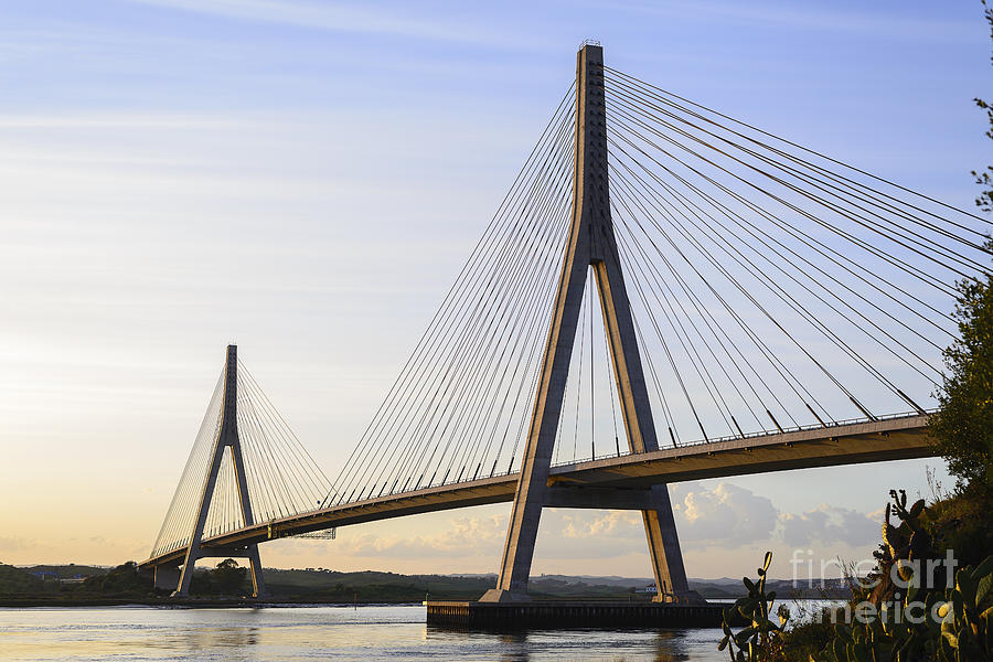
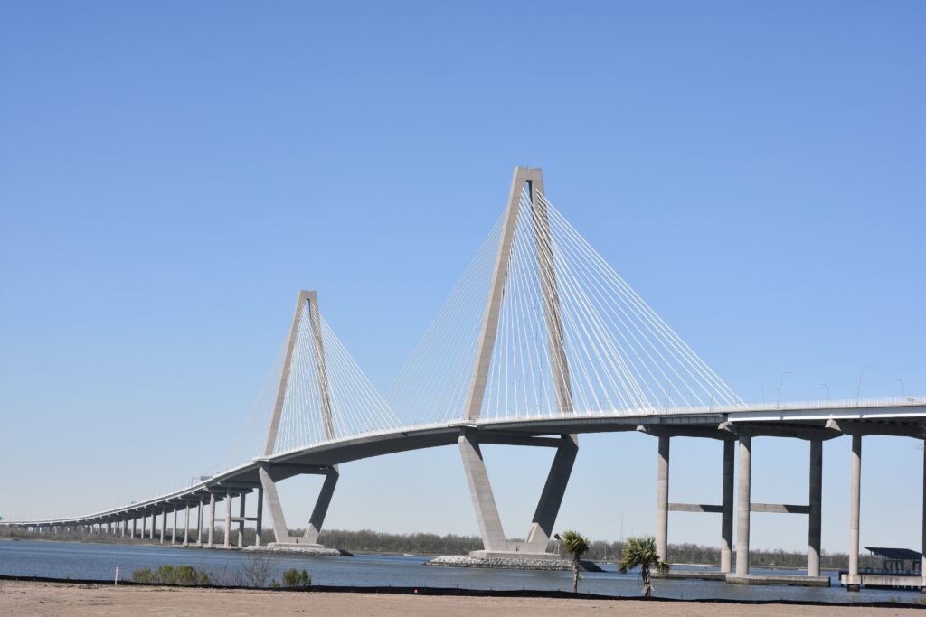
Three standard configurations for towers and cable planes are frequently utilized. The first configuration sees the very edge of the deck, supported by H-frame towers with double planes of cable-stays. This is beneficial for torsional stability but less aesthetically pleasing than other tower options. Also, in this form, the edge beams are directly supported by the cable-stays, which also offers the deck’s most straightforward solution. The deck slab is subsequently supported by concrete cross girders, which are often prestressed. To lighten the overall structure, the slab can be built as thin as 200–250 mm. To maintain the same straightforward deck solution, a second, more elegant configuration makes use of a single tower with an A-frame or inverted Y-frame and double planes of cable-stays (Figure 1). In the third arrangement, a single tower—which enters the deck’s centre—and a single plane of cable-stays are used. To provide the deck with torsional stability in accordance with this design, a central box girder is necessary (Figure 2).
Any of the three configurations will include towers that are largely in compression, making them excellent for construction with concrete. Towers can range in height from 30-160m and are typically made of a single box section that can be slip-formed or cast in discrete lifts of 4-6m1. The towers exhibit negligible moment under permanent loads due to the balanced cantilevering effects. The front stays carry the majority of the traffic loads in the main span, over the tower, and into the back stays, where they react against the piers or deck weight, producing relatively tiny moments in the towers. As a result, the towers can be built quite thin – the thinner they are, the less moment they attract, of course.
Cable-stays carry a vast majority of all their loads by forming the tension component of the overall strut-and-tie system. There are three types of cable-stay configuration, as briefly discussed above. Only the third system is used widely, as it is considerably more efficient.
Extradosed Bridges
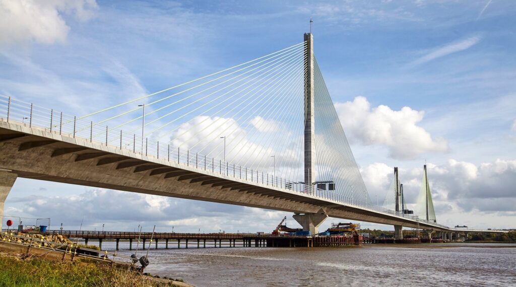
Consider extradosed bridges as hybrid solutions that sit somewhere between externally post-tensioned balanced cantilever beams and cable-stayed bridges. They are ideal for spans from about 100–300m1. Extradosed bridges can have a striking aesthetic appeal, but great care needs to be taken when choosing the depth of the bridge deck and the tower height, in order to create a good sense of proportion (Figure 3).
Extradosed bridges, typically feature a stiffer deck than a cable-stayed solution and a correspondingly shorter tower since they are a hybrid of beam and cable-stayed designs. In order to maximize their eccentricity, the exterior prestressing cables from within the deck are effectively taken outside the section at the piers (i.e., the extrados). But the cables can also act as a cable-stay by directly supporting the deck. By virtue of their similarity to cable-stayed bridges, extradosed bridges are almost always built in balanced cantilever. With the tower height typically around 1/10 of the main span, and the decks haunched or of constructed of a constant depth1. Typical section depths of 1/15–1/50 of the span at the piers, and 1/30–1/60 at midspan1. Typical configurations have twin towers, twin cable planes and edge beams or a single tower and single plane of extradosed cables arising out of a central torsion box.
The primary reason to employ extradosed bridges is in the ability to utilize external prestressing technology rather than the more expensive cable-stay technology. Since prestressing cables have a much smaller stress, whereas cable-stays have more, it therefore follows that as long as an extradosed bridge exhibits characteristics of a prestressed beam (such as low stress range in the cables), external prestressing technology can be used to it. However, it must use cable-stay technology as it starts to behave more like a cable-stayed bridge (with a higher stress range in the cables).
The construction of the deck segments can use either in situ or precast units. As the deck is often haunched, the first sections of the span are generally built without any cables coming from the section. Similarly, at midspan, the extradosed cables stop, as the shorter tower height makes any cables that come from the section too shallow, attracting too much load variation.
Stressed Ribbon Bridges
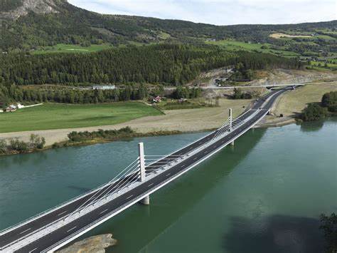
Concrete stressed ribbon bridges have a fairly flat appearance and are a special type of pedestrian suspension bridge. Typical spans range from 20 to 120 meters, however prestressed steel constructions can reach 200 meters1. They have a stunningly simple look, ideally suited to both areas of remarkable natural beauty and the urban scene, because they are nothing more than a flat catenary (Figure 4).
In their basic form, stressed ribbon bridges are simply concrete planks supported by steel suspension cables, with the actual stressed ribbon having the suspension cables fully prestressing the entire piece of concrete pathway. As the prestressed concrete absorbs the tension in the system, the ribbon becomes substantially stiffer, while the prestressing/ suspension cables maintain an almost constant force. Here, the catenary typically sags 1/40-1/60 of the span, compared to 1/10 for a standard suspension bridge1. Stressed ribbons are only appropriate for footbridges if the loads are light enough to be supported by the catenary’s shallow profile.
Given that the final gradient is approximately four times the sag-to-span ratio, the common pedestrian gradient of 1/12 necessitates sag-to-span ratio to be 1/48, which is extremely common. If a shallow pedestrian gradient of 1/20 is required for impaired users, sag-to-span ratio should be reduced to 1/80. However, this is too shallow for the catenary because creep, shrinkage, and temperature contraction would nearly completely obliterate the sag, rendering the ribbon incapable of sustaining the weight without massive axial forces. As a result, 1/20 gradients must be created by employing a raised floor supported by the ribbon, which can detract from the overall simplicity.
As a result, in most situations, a first set of cables is installed across the span, from which thin, precast concrete slab pieces are suspended. Before the entire concrete ribbon is prestressed further, the units are monolithically sewn together with in situ concrete. The thickness of the ribbon ranges between 200 and 400mm. Despite the fact that the overall forces in the ribbon are essentially estimated from the free moments split by the sag, the system is extremely nonlinear and extremely sensitive to the imposed deformations, namely the elastic, creep, shrinkage, and temperature stresses, all of which act on each other.
Hence, the design is exceedingly complex because the sag changes more frequently under all load conditions. The very enormous horizontal forces in the system must be carried to firm foundations at the extremities of the span, and even the slightest flexibility in these foundations will alter the sag of the ribbon. In addition to stiffening the ribbon, the concrete helps to distribute any concentrated applied loads with local moments in the ribbon. There can be significantly more substantial local moments at the extremities of the span, when the ribbon is constructed into the abutment or pier.
Footbridges
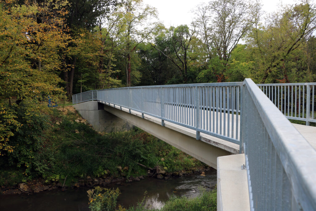
Concrete footbridges can be assumed to have been covered in the precursors to this article on ‘cast in place’ and ‘precast’ concrete bridges. However, one must note that pedestrian bridges use design loadings of (5kN/m2) which is a far cry from those of ordinary highway traffic (at least 10kN/m2). The safe use of the bridge by people with disabilities, parents pushing strollers, and cyclists must also be taken into account. This has an impact on the necessary gradients (no more than 1/20 is preferable), parapet layouts, and the usage of stairs and elevators, which can be very important to the project. With footbridges, aesthetics is frequently more important, and concrete’s flexibility in that it can be molded into practically any shape can be a tremendous asset in this regard (Figure 5).
Also, for footbridges, the amount of formwork and related falsework is relatively minimal and has little effect on the overall economy. Thus, cast in place solutions can be used for many of the most expressive footbridges. Where speed and convenience of construction are more crucial, precast solutions are also quite successful, and both standard and bespoke precast pieces are suitable. These precast elements, which can be composed of reinforced, pre-tensioned, or post-tensioned concrete, can be cast on-site or in precast factories. The level of the design and surface texture is crucial because pedestrian users always view the bridge up close.
The effects of wind or pedestrian loads on the dynamics of footbridges also need to be assessed more closely, but as concrete solutions are relatively heavy and stiff compared to steel footbridges, the dynamic design tends not to be critical except for the slenderest structures.
Rail Bridges
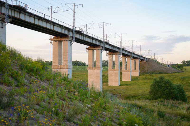
Similar to footbridges, all the concrete bridge types described in the earlier articles also applies, except that railway bridges have some additional design features which the designer must consider. The most obvious of them all, being the increase in loading. While light rail or metro systems (Figure 6) actually have loads that are similar to those of highways, there are heavier metros and normal rail systems that can have loads that are two to three times greater than that of normal highway traffic.
Although the design of most bridge superstructure is often driven by the vertical loads, railway bridges also tend to be designed for higher lateral and longitudinal loads as a result of a variety of braking, traction, centrifugal, and nosing forces, which will considerably alter the substructure design. Additionally, dynamic impacts from railroads are far more significant than those from highways, particularly for shorter spans. Dynamic factors, which can range from 1.0 for very long spans (over about 70m) to 2.0 for very short spans (less than 3–4m), often increase loads1. High-speed rail systems will require special study, and it is important to evaluate the dynamics of both the train and the bridge construction. Fatigue should also be considered for all railway bridges, although with the use of well-detailed, unwelded reinforcing bars in reinforced concrete, or fully prestressed concrete (where the concrete is always in compression and the prestressing steel has a very low stress range), fatigue is rarely a dominant issue.
Another significant difference in the design of rail bridges is that, whilst it is generally preferable to maximize the distance between structural expansion joints in highway bridges, the railway environment can be different, as more frequent joints in the structure are sometimes preferred so as to eliminate any rail joints, which can be expensive and need regular maintenance. In this case, the interaction between the continuous track and the jointed structure will need to be assessed, as this can significantly affect the longitudinal loads in the system, especially with track slab (as opposed to ballasted) solutions.
Conclusion
Along with the unique characteristics of concrete footbridges and railway bridges, the specialized nature of concrete cable-stayed, extradosed, and stressed ribbon bridges has been described. In the December issue, a final essay on the long-term maintenance of all concrete bridges brings this series to a close.
Also See: Selecting a Concrete Bridge Type
Sources & Citation
- Concrete Bridge Development Group (2014) ‘Concrete Bridge Design and Construction series No. 6: Concrete bridge construction methods — Specialist Concrete Bridges’, The Structural Engineer, 92 (11), pp. 34–39
- Construction (2nd ed.), London, UK: ICE Publishing Concrete Bridge Development Group (In press) Technical Guide No. 14: Best Construction Methods for Concrete Bridge Decks, Camberley, UK: CBDG