
The reading and interpretation of structural engineering drawings is a much-underrated skill. A skill that is often not taught but learnt through frequent exposure to structural engineering contents and a drive to fully understand them. In simple form, a structural drawing can be defined as any drawing consisting of plans or set of plans and details explicitly showing how a building or structure will be constructed. Every structural drawing produced must achieve one purpose. It must effectively communicate the engineer’s intentions on paper, and it must do so unambiguously. This is fundamental and very key for any drawing issued by a structural engineer. From a very complex general arrangement to a simple sketch made on a site, the structural drawing must be well defined and clear of jargons.
In this article, many of the common as well as some unfamiliar structural drawing connotations will be listed and explained. This includes texts, symbols and variables. Their relationship with the drawings of other members of the design team will also be highlighted where necessary. The reader should note that, this article is particularly written with a bias to building structures, hence where the contractual specifications are defined, it would reflect the forgoing.
Structural Drawing Principles
As stated in the preceding section, a structural drawing is a type of engineering drawing consisting of a set of plans and details, showing how a structure will be constructed. This entails that a structural drawing is invariably concerned with the load-carrying members of a structure – the flooring system, the beams, columns and the foundations. The structural drawing outlines the sizes of this structural elements as well as the material specifications.
A structural drawing normally has different subsets, each of which holds different information. This includes:
- General Arrangement (G.A)
- Sections
- Elevations
- Structural Details
- General/Drawing Notes
General Arrangement (GA)
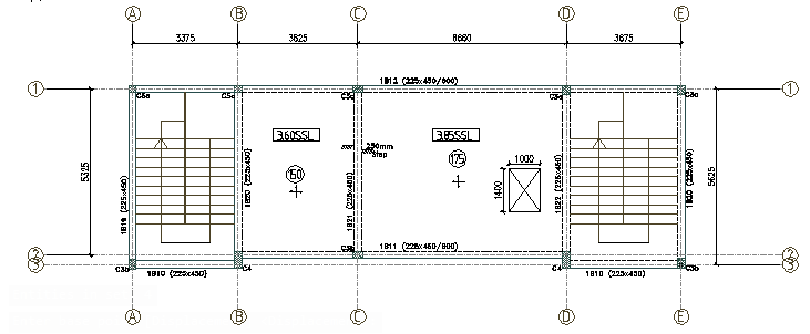
The general arrangement drawing can be equated to the architectural plans, but in the case of a structural drawing, they hold the information on the size and disposition of the structural elements in the respective plans. The GA is very key to where sections through the structure are taken and presented, they present useful information on the elements in the structure, such as the shear walls, concrete columns, beams, voids, floor slabs etc.
A typical structural drawing normally includes GA for the foundation, floors and roof. Generally, it’s the responsibility of the architect to provide the building setting out information. It is based on this information that the structural engineer produces GAs. Wherever discrepancies exist between a structural engineer’s GA and architect drawing this should be resolved by bringing same to the design team’s attention. (Figure 1 is an example of GA for a concrete building).
Sections
A section is a cut or slice through a structure, usually taken in order to describe the interface between structural elements. Interfaces cannot be clearly identified on plans, and since a structural drawing has to be unambiguous, thus sections must be provided for clarity. They are usually employed using an orientation that is up the page or towards the ‘left’ of the page. Where an element is cut, its outline is usually drawn with a thicker line and in many instances hatched or shaded. See Figure 2
There is a rule in drawing sections. It requires that only details that are within a metre away from the cut is drawn. For example, if a core wall exists 2m away from a section cut, the shear wall is not drawn, as it is taken to be to far to be seen by the section slice. If an attempt is made to show everything, past the sections cut, sections would be a mess of vertical elements. This would defeat the main purpose of providing sections which is indeed for clarity.
Elevations
Elevations are a side view of elements in the structure. They are often confused with sections, because just like sections, they are a cut through the structure, showing the vertical plane. However, an elevation is at the very face of the element that is being viewed. The purpose of an elevation is to illustrate the flow and interaction between vertical elements and horizontal elements of the structure.
Typically, in concrete structures, elevations only show the lateral stability elements of the building, which includes the shear walls and concrete cores, since an overall elevation will not show anything other than what is already contained within the architect’s drawing. However, for steel or timber frames, it’s very common to show the overall building elevation. In steel and timber frames, they show very crucial information on levels and help to ensure that there is no conflict in the disposition of vertical, horizontal and diagonal members. Figure 3 shows the elevations of a concrete core and a steel braced frame.

Structural Details
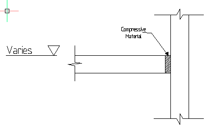
This provided information on how the structural elements are to be constructed or connected. They are typically produced following the drawing of the GA as their requirement is brought to light as the GA drawings are developed. For example, if there’s a need to show how a slab would be isolated from a wall, then a detail is required to show this (Figure 4).
General/ Drawing Notes
The general notes or drawing notes are usually provided as part of the structural drawing. They contain information regarding material properties, construction requirement and procedures.
Notes can also be used to highlight areas which will be subjected to further design development, or information that are difficult to draw.
Drawing Connotations
A typical structural drawing consists of many texts, symbols and nomenclatures which assist in outlining the setting out information explicitly. Sometimes there might be slight variations between these symbols, but they all follow the same process.
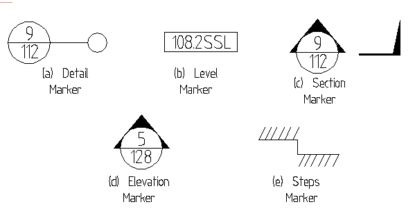
- Detail Marker: The detail marker is used to show information on the GA to tiny or not visible on plans. It is usually denoted with a line pointing to a circle where the detail is being taken (Figure 5a). The lower part of the circle contains the drawing number or where the detail is drawn.
- Level Marker: The level marker is used to describe the level of a GA from a referenced datum. It is denoted by a box holding the level (Figure 5b). Typically, a level marker is suffixed with one of the following: (SSL – Structural Slab Level, TOS – Top of Steel, (TOF – Top of Foundation) or (AOD – Above Ordnance Datum).
- Section Mark: A section marker is denoted with an arrow showing the point where a cut for which a section has been taken and its orientation. There is usually an accompanying arrow, showing the extent of the section (Figure 5c). As in the detail marker, the lower part of the circle holds the drawing number or where the section is drawn.
- Elevation Mark: An elevation mark is used to show an area of a GA that is being elevated. Where an elevation is on a gridline, they can be used to match the reference e.g., in (Figure 5d), this mark is for an elevation on gridline 5.
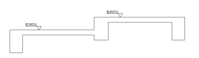
- Steps Mark: The steps mark is used to identify lines at a change in level. They are normally identified by adding sectional hatching to the plan (See Figure 5e)
Other symbols that may be found on GA’s include, level marker on sections and elevations, thickness of slab marker, Hole or void in a structural element, recess in structural elements and span arrow usually indicating the direction of spanning of a floor slab. All of these, are illustrated in Figure 6.

Line Types and Line Weights
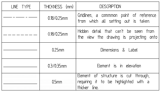
Line type and line weights are a very important component of GA drawings. They are used to define what is conveyed in terms of location and size. Figure 7 gives some examples of line types and line weights found in GA drawings and where they might be applicable.
Units and Scaling
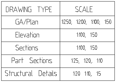
The units employed in GA drawings is usually stated in millimetres (mm) while levels are described in metres. For scaling of drawings, there are standards set that are used when creating drawings. Their use will depend on the type of drawing to be produced. Figure 8 provides a list of scales used depending on the type of drawing produced. This list is however, not all-inclusive. There are many instances where the recommended scale might not be realistic, however in any case, the scales should be chosen such that all parameters in the structural drawing is visible upon printing.
Labelling Protocol
There are protocols for labelling of items, referenced items such as elevations, sections or even structural details on a drawing. This label can take the form of a letter, number or a combination of both. The letter ‘B’ is typically used to denote beams, ‘C’ for columns and ‘F’ for isolated foundations.
Scheduling
In many instances, an element will be found to be common throughout large tranches of the structure, in such instances it is advisable to create a schedule rather than draw the same elements multiple times. This is generally done in the case of columns, where they are simply placed on a sheet showing the cross-section dimensions only.
Change Indication
Revisions and abeyance are very natural in design and construction. Design itself, by nature is an evolving process and drawings are continually revised to reflect this. Revisions are normally identified through the use of clouds around the affected area in a drawing and then marking it with a triangle which has a letter or number contained within it (Figure 9a). This marker corresponds with the revision on the drawing while the details of the revision is explained in the revision panel of the drawing sheet.
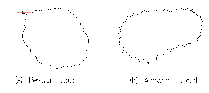
Another form of cloud is the abeyance cloud (Figure 9b). This indicates a section of the drawing that is on hold, of which the information contained therein should not be referred to or digested. Typically, abeyance clouds appear because outstanding information and/or confirmation from other members of the design team is yet to be available at the time the drawing is being issued.
Drawing Interpretation
The Interpretation of the drawing depends on the type of structure under consideration, whether the building is to be done in concrete or steel which are the most prominent materials for building structures.
Interpreting Concrete Drawings
All reinforced concrete structural drawings are intended to communicate to the builder the layout of bars within concrete elements of the structure. The only dimensions provided in them relates to the reinforcement whose placement is cannot be fixed to a reference point.
All reinforced concrete drawings are read in conjunction with the general arrangement drawings, as this will provide the setting out dimensions of the structural elements themselves, excluding the reinforcement contained within them. A typical reinforced concrete drawing contains in addition to the GA’s, at least four types of structural details, which are explained below.
Beam Rebar Drawing
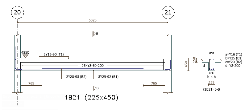
The beams rebar details are considered amongst the simplest structural members to create drawings for. The information contained within them, includes the bars call-up, the beam size and the sections. Beam rebar details, should show clearly the extent of bars and how they lap with each other. This is done by showing marker arrows with a bar mark number showing how far one bar laps with the other. Some bars need to be set out in layers this is usually denoted in the callup. For example, a bar with the notation ‘T1’ is the first layer at the top while ‘B2’ means the bar is the second layer at the Bottom. Figure 10 shows a single span concrete beam detail.
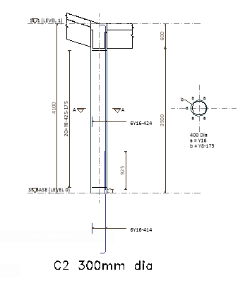
Column Rebar Drawing
In contrast to beam rebar drawings, column rebar drawings are more diagrammatic. They must show the primary reinforcement and extents of the containment links. A section is also cut through the column to show the disposition of rebars on plan. Figure 11 is an example of reinforced concrete column.
Wall Rebar Drawing
Wall’s rebar drawings within reinforced concrete structures are very similar to those of columns. The basic difference being that the rebars call out, in some instances use the notation (N1, N2 or F1, F2) to denote the bar layer.
Floor Slab Rebar Drawing
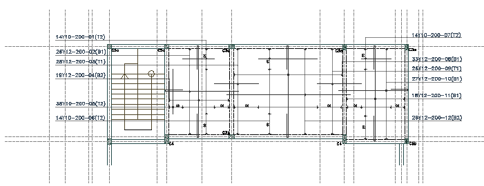
The reinforced concrete slab drawings are by far the most complex drawing to understand. This is even more true for flat slabs, where there’s a need to concentrate sections of reinforcement that acts as beams within the slab. With a minimum of four layers of reinforcement to be plot and the curtailment of the bars needing to be carefully plotted out. In many instances, it is common to find drawings showing the reinforcements in a floor slab being clustered with a lot of details, becoming difficult to read. Thus sometimes, it is preferable to create two separate plans, one showing the top bars (T1- first layer at the top, T2- second layer at the top) and the other showing the bottom bars (B1-first layer at the bottom, B2-second layer at the bottom) Figure 12.
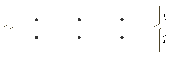
Just like the concrete beam rebar drawings, extent indicators of the rebars are very key on a floor slab drawing. These indicators show the area occupied by a bar, as well as the centres they are placed at. Figure 13 shows a section of a reinforced concrete floor slab.
Interpreting Steel Drawings
Steel drawings are mostly not fragmented as in concrete structures, in most instances almost all the details can be shown on the GA, with the exception of connections which are shown on different drawings. Steel structural drawings are usually more diagrammatic than concrete structural drawing. In fact, it is advised, that when producing steel drawings, a diagrammatic style should be employed. In preparing their G.A all beams and trusses are drawn as single line. The labelling of the structural elements should adopt a South -North/Down to Up and East to West/Right to Left method.
Design Intent General Arrangement Drawing Protocol
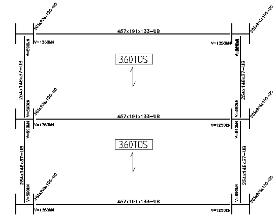
For building projects, the responsibility of the design and detailing of the steel connection usually fall within the remit of the steel fabricator, notwithstanding, the responsibility for the overall design is with the design engineer. Hence the design engineer must ensure that all drawings meet the design requirement. For this reason, the design general arrangement produced by the design engineer do not include any details on the sizing of the bolts, plates and welds that make up the connections. They do however, show the ultimate reactions at the supports, which is utilized by the steel frame fabricator in designing the steel connections. Figure 14 is the GA of a steel frame showing the steel columns, beam and the reactions.
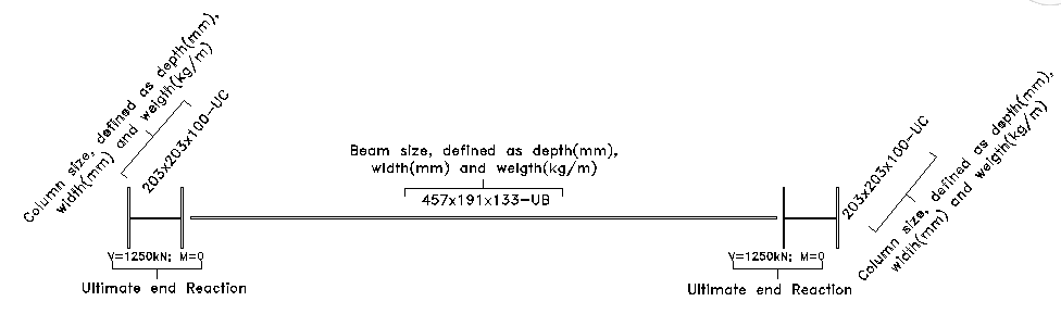
In steel buildings, the labelling system employed for the GA’s. is dependent on the type of steel sections being employed. For conventional open steel sections such as I and H columns the protocol is as follows
Depth (mm) × Width (mm) × Weight per metre length (kg/m)
For angle and closed steel sections, the weight per meter length is replaced with the section thickness. This is usually defined as:
Depth (mm) × Width (mm) × Thickness (mm)
Figure 15 shows a general arrangement drawing, with examples of all the structural elements described previously. Note that the beams are always drawn with gabs towards the support as they connect with the columns. This indicates that the steel beams are not continuous
Steel Fabricator General Arrangement Drawing Protocol
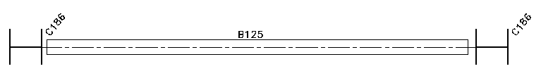
The general arrangement developed by the design engineer shows all structural elements on a single plan. However, the one developed by the steel fabricator, shows only the steelwork elements of the structure. The steel beams are drawn to scale in plan and rather than label the size of the elements in the frame, the fabricator instead give them a unique marker. These markers are used to designate the structural elements, which the steel fabricator refers to when constructing the steel frame. Figure 16 is an example of the same steel beam shown in Figure 14, as it would appear in a steel fabrication general arrangement.
Steel Fabrication Shop Drawing
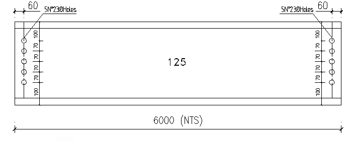
This is basically the drawing developed by the steel fabricator for use. Every element in a steel frame must have a fabrication drawing produced for it. These would show what needs to be done to the steel elements in order for it to be installed within the frame. This includes bolt holes, fin plates, welds and stiffeners that are developed based on the connection design. In some instances, these drawings show the connection data to scale, but the length of the element is not. Instead, the element length is defined but highlighted to scale. This is a form of shorthand illustrating the element drawn to a larger and easier to read scale without having to draw the whole length. Figure 17 is the fabrication drawing of the steel beam shown in Figure 14.
From 3D to 2D
The introduction of Building Information Modelling (BIM) has significantly affected the creation and interpretation of structural drawings. BIM models are three dimensional, it is a move away from the traditional two-dimensional based method which this article focuses on. However, two-dimensional drawings are still needed regardless, because even where a BIM model is in use, two-dimensional drawings will still be required for design information to be passed to the contractors/fabricators as well as other members of the design team. This is done by extracting views and details from the BIM model and placing them onto a 2D drawing. Such drawings follow the same protocols as described in this article.
See: Concrete Slabs in Concrete Frame Buildings
Sources & Citations
- The Institution of Structural Engineers (2006) Standard Method of Detailing Structural Concrete. 3rd ed. London: The Institution of Structural Engineers
- The Institution of Structural Engineers (2013) Drawing Nomenclatures. Technical Guidance Notes 31(1).
- The Institution of Structural Engineers (2012) Reading Reinforced Concrete Drawings. Technical Guidance Notes 12(1).
- The Institution of Structural Engineers (2012) Reading Structural Steelwork Drawings. Technical Guidance Notes 13(1).
Thank You!