When a structural element is subjected to an eccentric loading there is that tendency for it to rotate along its axis. This rotation can develop significant forces within the structural element, which it may not have being designed to resist. This twisting/rotation is known as torsion. Torsion generates forces within structural elements that they are rarely efficient at resisting. It would normally result in significant increase in element size or ultimately lead to change in structural form where they are found to be acting. Torsion in structures is best avoided as far as possible. It is when it cannot be avoided and a design against torsion is the only resort should a design be considered.
In design of steel elements, closed steel sections are more resistant to torsion than open sections, by virtue of the nature of their section. This would be appreciated later in the article.
When designing steel elements against torsion, the following checks must be carried out:
- Check the section complies with classification requirements described in BS EN 1993-1-1.
- Calculate the magnitude of the stresses due to the applied torsion.
- Calculate the combined effects of the longitudinal stresses in the beam due to torsion and bending.
- Check these effects against the design strength of the steel element.
- Review the angle of twist to ensure it meets serviceability criteria.
- Check for buckling effects where applicable; see SCI publication P385: Design of Steel Beams in Torsion
Design Principles
The elastic theory of torsion in uniform bars is well defined and understood within texts on ‘strength of materials’ and ‘theory of structures.’ Hence the theoretical basis is not explored here. This article will only attempt to review the design basis from a steel design perspective, with respect to steel sections.
Torsion in steel can be broken down into two components. These are:
St Venant’s Torsion
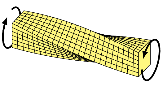
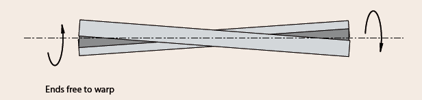
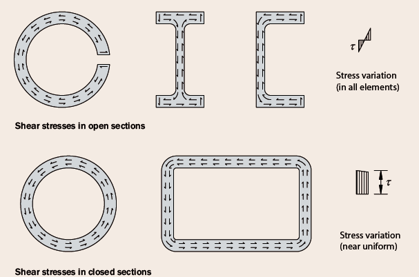
Consider a uniform bar, subjected to an equal but opposite torque (Figure 1) at its ends. Should the ends be free to warp out of their planes, the stresses developed in the bar is known as ‘Pure Torsion’ or ‘St Venant Torsion named after the theory originator, St Venant. (Figure 2) shows the stress pattern for some of the most common steel sections. The torsion is resisted through a flow of shear forces around the section, which rotates about its shear centre. The St Venant torsional stiffness of open sections is very low because the lever arm of the shear flow is very small.
Consequently, the effectiveness of closed section in torsion can be appreciated by comparing the pattern of their shear stresses with those of open sections in Figure 2. For closed section, the shear stresses form a loop in the same rotational direction thus, maximizing their section use. Whereas in the case of the open sections, the shear stresses are in opposite directions in opposite faces, thus less efficient in providing torsional resistance.
Warping Torsion
Supposing the warping of the steel section is constraints, additional longitudinal stresses are induced in the member. To illustrate the effect of warping restraint, consider the same uniform bar described earlier, now having the torque applied in the middle and restraints from warping, the displacement in contrast to Figure 1 would be Figure 3.
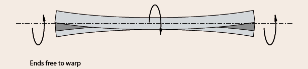
Assuming both both halves of the beam were separate, the twisting of the bar would’ve been such as Figure 1, but in the opposite sense. However, since the torque is applied in the middle, warping is fully restrained at the location and thus the bar is constraints to bend in plan and can only twist at varying rate over each half span.
Warping torsion is being resisted through minor axis bending of the flanges in opposing directions.
Determining Torsion Stresses
At any point within the span of any member subjected to torsion, the torsion is being resisted by a combination of St Venant torsion and warping torsion. This is expressed in Clause 6.2.7 of BS EN 1993-1-1 as:
{ T }_{ Ed }={ T }_{ t,Ed }+{ T }_{ w,Ed }Where: TEd is the ultimate applied torsional moment, Tt,Ed is the component of the applied moment resisted by St Venant torsion and Tw,Ed is the other component of the applied moment being resisted by the warping torsion.
{ T }_{ t,Ed }=G{ I }_{ T }{ \phi }'\quad { T }_{ w,Ed }={ EI }_{ W }\phi ''Where: G is the shear modulus of steel, IT is St Venant constant, IW is the warping constant, ϕ is the rotation of the beam about its axis ϕ’ is the first derivative of the rotation ϕ’’ is the second derivative of the rotation ϕ’’’ is the third derivative of the rotation.
Estimating the components of this applied torsional moment is usually based on the deformed shape of the element under torsion. And the way in which the element deforms depends on its span, restraint at the point of support and form of applied torque. This is represented by the value of derivatives of the rotation ϕ’ and ϕ’’’.
For simply supported beams, having sufficiently restrained supports subjected to uniformly distributed torsional moment applied to them along their length, the value of this derivative may be estimated from the following equations
\phi '=\left[ \frac { Ta }{ { GI }_{ T }L } \right] \frac { L }{ 2a } -\frac { x }{ a } sinh\left( \frac { x }{ a } \right) \\ -tanh\left( \frac { L }{ 2a } \right) cosh\left( \frac { x }{ a } \right) \phi '''=\left[ \frac { T }{ { GI }_{ T }La } \right] sinh\left( \frac { x }{ a } \right) \\ -tanh\left( \frac { L }{ 2a } \right) cosh\left( \frac { x }{ a } \right) Where: T is the applied torque; x is location of the point of application of the torsional stress; L is the length of the steel element; and a is the torsional bending constant as defined below:
a=\sqrt { \frac { { EI }_{ W } }{ { GI }_{ T } } } In the case of other supports, loading conditions the equations provided above for the values of the derivative of rotation is not valid since the deformed shape would be different. However, guidance may be obtained from the SCI publication listed in the ‘Sources and Citation” section of this article.
Having determined the value of the applied torsional moment, its value is compared with the steel section’s torsional resistance Mf,Rd. The next section will explain how this is done.
Combined Bending & Torsion
Quite often, steel elements resisting torsion are simultaneously having to resist bending, this entails that such elements must be assessed for combined action. This is usually done through a unity check, similar to the assessment of elements undergoing biaxial loading.
Clause 6.2.9.2 of BS EN 1993-1-1 gives the equation for carrying out this check, as presented below:
\frac { { M }_{ y,Ed } }{ { M }_{ y,el,Rd } } +\frac { { M }_{ z,Ed } }{ { M }_{ z,el,Rd } } +\frac { { M }_{ w,Ed } }{ { M }_{ f,Rd } } \le 1Where: My,Ed & Mz,Ed is the design bending moment in the major axis and minor axis respectively; My,el,Rd & Mz,el,Rd is the elastic bending moment resistance in the major axis and minor axis respectively. While Mw,Ed is the design warping moment acting on a single flange and Mf,Rd is the torsional bending strength taken as half the value of the elastic bending resistance about the minor axis.
The design warping moment acting on a single flange can be estimated from:
{ M }_{ w,Ed }=\frac { { EI }_{ w }\phi '' }{ { \left( h-{ t }_{ f } \right) } } Where: E, Iw & ϕ’’ is as defined earlier; h is the overall depth of the section and tf is the thickness of the flange.
\phi ''=\left[ \frac { T }{ { GI }_{ T }L } \right] -1+cosh\left( \frac { x }{ a } \right) \\ -tanh\left( \frac { L }{ 2a } \right) sinh\left( \frac { x }{ a } \right) Note that the equation for warping moment is only valid for doubly symmetrical steel sections, for unsymmetrical sections, the SCI texts at the end of the article should be consulted.
Serviceability
The effect of torsion on structural elements is to cause rotation. This rotation can sometimes lead to movements that cannot be withstood by other components of a structure; thus, it is generally recommended to restrict the amount of rotation structural elements are able to undergo.
{ \phi}_{ ULT }=\frac { TL }{ G{ I }_{ T } } “The rotation of a steel element subjected to torsion shall not be greater than 2° from its original position.”
BS EN 1993-1-1
When assessing the actual value of the rotation, it is the characteristic value of the applied actions that is considered just as it applies for any case of serviceability limit state.
Worked Example
A simply supported steel beam in a newly refurbished building is required to span 6m, supporting a steel floor that applies an ultimate point load of 45kN at midspan and at eccentricity of 50mm. Assuming the support of this beam has no warping restraints but is provided with sufficient lateral and torsional restraints, determine the adequacy of a 305 x 102 x 25 UKB section in grade S355.
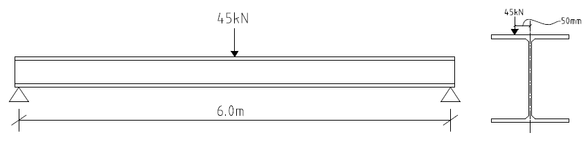
Properties: IT = 4.77cm4 ; IW = 0.027dm6 ; h = 305.1mm ; tf = 7.0mm ; Wel,y = 292cm3 ; Wel,z = 24.2cm3.
Scroll the tab below for the solution to the worked example.
See: Design of Steel Element in Axial Compression
Sources & Citation
- Hughes A.F., Iles D.C. and Malik A.S. (2011) P385: Design of steel beams in torsion, Ascot: Steel Construction Institute.
- BS EN 1993-1-1:2005+A1:2014 Eurocode 3: Design of steel structures. General rules and rules for buildings
- NA+A1:2014 to BS EN 1993-1- 1:2005+A1:14 UK National Annex to Eurocode 3: Design of steel structures. General rules and rules for buildings
- Institution of Structural Engineers (2021) ‘Technical Guidance Note Level 3, No. 1: Designing for Torsion in Open Steel Element’, The Structural Engineer, 95 (7), pp. 34–37
Thank You!