
Introduction
For every structure, it is the function of the foundation to transfer all the loads coming from the superstructure to the underlying soil on which it rests. A properly designed foundation must deliver these loads to the soil without overstressing the soil which could otherwise cause excessive settlement or shear failure of the bearing soil. In-order to avoid overstressing the soil geotechnical engineers and structural engineers must determine the bearing capacity of the soil upon which the structure is to be founded. The bearing capacity is the amount of stress that can be withstood by a soil without causing any adverse effect. Determining the bearing capacity applies to all forms of foundation, from a simple pad footing to a large pile group. The bearing stress capacity of the soil is the most key variable and a direct indicator of the form and size of foundations.
This post deals with the geotechnical design of spread foundations. It explains the principles of how the
Design Principles
The bearing capacity of a soil is dependent upon the composition of the underlying soil as well as its engineering properties – bulk density, moisture content, void ratio are all indicators of the soil bearing capacity and the type of foundation that will likely be placed upon it. It is important therefore necessary to be familiar with the various types of soil that can be encountered. From simply knowing the soil type, it is possible to develop reasonable design solutions for any given sub-structure.
Eurocode Methodologies of Assessing Bearing Capacity
The subject of bearing capacity fall within the purview of geotechnical engineering. Geotechnical engineering has a reputation of being imprecise and the design of its structures is practiced as an art rather than a science due to the varying nature of soils and it interactions with the substructures placed upon it. “BS EN 1997-1 – Eurocode 7: Geotechnical Design – Part 1 General Rules” recognizes this and lists four differing methods that can be applied in determining the bearing capacity of soils for foundation design.. All of four methods are equally valid, the major difference relating to efficiency and economy. A method will produce more efficient and economical solutions than others depending on the degrees of accuracy of modelling the soil conditions.
Geotechnical Design by Calculation
This method is reliant on the quality of data retrieved from geotechnical investigations carried out on the prospective site. Assumptions are made based on this data and in some instances simplifications will need to be applied to the calculation model that can lead to conservative results. For more details on this method see Clause 2.4 of BS EN 1997-1.
Geotechnical Design based on load tests and experimental models
In addition to geotechnical investigations that focus on the soil type and location of the water table, it is possible to carry out tests to determine the soil’s bearing capacity. These tests provide unique results for that particular site and thus are more accurate than making assumptions based on data collected from a standard investigation. This approach typically results in economical design solutions due to the accuracy of the data. Load tests however need to be at the correct scale to ensure the test mirrors the proposed foundation, which can prove to be expensive. See Clause 2.6 of BS EN 1997-1.
Geotechnical Design by Observation
In instances where it is not possible to predict how the soil will interact with a proposed substructure, it is possible to apply an observational based method of design. This requires the design of the substructure to be continuously altered as new data is revealed about the soil during the course of constructing the foundations. Careful monitoring is needed throughout the construction process, as well as quick responses to the data being delivered, in order to prevent delays during the substructure works. This method is unlikely to provide a practical approach to the majority of foundation designs and is not recommended for designing substructures for buildings. For a more comprehensive description see Clause 2.7 of BS EN 1997-1.
Geotechnical Design by Prescription
In instances where the soil conditions of the site are well known, it is possible to prepare a set of parameters against which any sub-structure can be designed. Due to the generalized nature of this method, it’s common for it to produce conservatively designed solutions. For more information see Clause 2.5 of BS EN 1997-1.
Determining Undrained Soil Bearing Capacity
BS EN 1997-1 states that the ultimate bearing resistance of a soil must be greater than the applied bearing pressure from the substructure. In numerical terms this is expressed thus:
{ V }_{ d }\le { R }_{ d }Where:
- Vd is the design vertical load, that is acting normal to the foundation’s base.
- Rd is the design bearing resistance of the soil
There are two equations for calculating base bearing capacity of a given soil. They are dependent on the condition of the soil, which is referred to as ‘drained’ or ‘un-drained’. For cohesive soils such as clay, un-drained design approach applies when placed under a short term load, as the force would be resisted by pore pressure rather than the grains that form the soil.
For un-drained soil Rd is defined thus:
\frac { { R }_{ d } }{ { A }^{ ' } } =(\pi +2){ c }_{ u;d }\cdot { b }_{ c }\cdot { s }_{ c }\cdot { i }_{ c }\cdot qWhere:
- A’ is the effective base area of the foundation
- Cu;d is the design un-drained shear strength
- bc is the base inclination factor, if it is placed on sloping ground
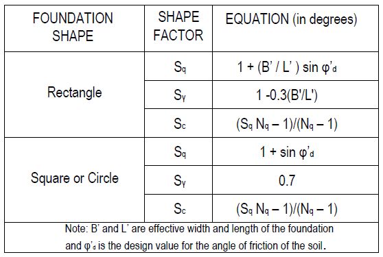
- Sc is the shape factor of the foundation
- ic is the load inclination factor
- q is the overburden pressure at the base of the foundation
The effective area is based on how the load is applied to the foundation. If the load is eccentric to the centre of the foundation, then the area over which the load is applied to the soil from the foundation, is reduced. For the purposes of this note however, the assumption of all loads acting normal to the base with no eccentricity, will be made.
The design un-drained shear strength is defined as:
{ c }_{ u;d }=\frac { { c }_{ u;k } }{ { \gamma }_{ c } } Where:
- cu;k is the undrained shear strength of the soil, which is a measured property
- γuc is the partial factor for the undrained shear strength
The overburden pressure ‘q’ is the vertical effective weight of the soil that is located above the strata level where the foundation is to be installed. This post does not cover bases on inclined slopes for the sake of simplicity. Hence the base inclination and load inclination factors are not discussed.
Determining Drained Soil Bearing Capacity
In the case of drained soils, reliance can be placed on the friction between the particles within the soil. As such the equation for determining bearing capacity includes the factors that are influenced by the angle of friction (φ)
For drained soil, ‘Rd‘ is defined thus:
\frac { { R }_{ d } }{ A' } =\left( { c' }_{ d }\cdot { N }_{ c }\cdot { b }_{ c }\cdot { s }_{ c }\cdot { i }_{ c } \right) +\left( q'\cdot { N }_{ q }\cdot { b }_{ q }\cdot { s }_{ q }\cdot { i }_{ q } \right) \\+\frac { 1 }{ 2 } \left( \gamma '\cdot B'\cdot { N }_{ \gamma }\cdot { b }_{ r }\cdot { s }_{ \gamma }\cdot { i }_{ \gamma }\cdot \right) Where:
c’d is the design effective cohesion- q’ is the overburden pressure at the base of the foundation
- γ’ is the effective weight density of the soil at the strata level of the foundation
bc , bq and bγ are base inclination factorssc , sq and sγ are shape factors – see figure 1 for derivation-
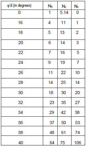
Nc , Nq and Nγ are the bearing capacity factors (Table 2)
Partial factors to soil properties
BS EN 1997-1 requires all material properties of soils to have a partial factor applied to them. This is due to the adoption of limit state theory to the design of substructures. There are two sets of factors that need to be applied to the material based on the applied load combination that is being considered. The following load combinations are to be used:
Combination 1: Permanent load x 1.35 + Variable load x 1.5 matched with set ‘M1’ properties. This is described as Set B in BS EN 1990
Combination 2: Permanent load x 1.00 + Variable load x 1.3 matched with set ‘M2’ properties. This is described as Set C in BS EN 1990.
The load set providing the worst condition is deemed to be the design case. Table 3 lists the values of the partial factors for material properties mentioned in this note
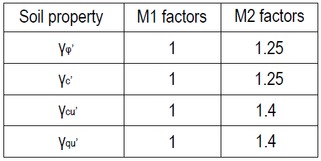
*This partial factor is applied to φd using the following equation:
{ \phi ' }_{ d }={ Tan }^{ -1 }\left( \frac { Tan{ \phi ' }_{ k } }{ { \gamma }_{ \phi ' } } \right) All other partial factors are applied as a denominator for the relevant soil properties.
Displacement and settlement of foundations
In addition to determining the design bearing capacity of
As a general rule, if the ratio of design bearing capacity against the applied characteristic load is equal to or greater than 3, then no assessment of settlement is required. Note that this rule only applies to clay soils.
If however, the loading parameters do not meet this criteria then a settlement analysis of the foundations are required. This is a complex task and as a result beyond the scope of this post.
Worked Example
A pad foundation measuring 0.75m x 0.75m with a thickness of 500mm is to be placed on a site with a sand/gravel soil. The water table is 3m below ground level and footings are founded 1.5m below ground level. The load combinations onto the pad footing are 750 kN/m2 for Combination 1 and 385 kN/m2 for Combination 2. Determine whether the soil can accommodate this applied bearing pressure.
Soil Properties: φ’ = 30º, γ’ = 17 kN/m3, c’=0
Since the soil is cohesion less and water table is below the base of the footing we can assume a drained condition.
Therefore the bearing capacity of the soil is given as shown below when cohesion, c=0
\frac { { R }_{ d } }{ A' } =\left( q'\cdot { N }_{ q }\cdot { s }_{ q }\cdot \right) +\frac { 1 }{ 2 } \left( \gamma '\cdot B'\cdot { N }_{ \gamma }\cdot { s }_{ \gamma } \right) N:B The base factors do not apply because the base is horizontal, and the inclination factors do not apply as well since the load is not applied at an angle.
Combination 1
q=\gamma d=1.5\times 17=25.5kN/{ m }^{ 2 }\\ { N }_{ q }=18;\quad { S }_{ q }=(1+sin30)=1.5;\quad \\{ N }_{ \gamma }=20;\quad { S }_{ \gamma }=0.7\frac { { R }_{ d } }{ A' } = \left( 25.5\times 18\times 1.5 \right) +\quad\frac { 1 }{ 2 } (17\times 0.75\times 20\times 0.7)= =778kN/{ m }^{ 2 }>750kN/{ m }^{ 2 }Combination 2
q=\gamma d=17\times 1.5=25.5kN/{ m }^{ 2 } { \phi ' }_{ d }={ Tan }^{ -1 }\left( \frac { Tan{ \phi ' }_{ k } }{ { \gamma }_{ \phi ' } } \right) ={ Tan }^{ -1 }\left( \frac { Tan30 }{ 1.25 } \right) \\=24.8^{ \circ }{ N }_{ q }=10;\quad { N }_{ \gamma }=8.5;\quad { S }_{ q }=(1+sin24.8)\\=1.42;\quad { S }_{ \gamma }=0.7\frac { { R }_{ d } }{ A' } =\quad \left( 25.5\times 10\times 1.42 \right) \\+\frac { 1 }{ 2 } (17\times 0.75\times 8.5\times 0.7)\quad \quad \quad =400kN/{ m }^{ 2 }>385kN/{ m }^{ 2 }Therefore the applied pressure is within the allowable bearing pressure of the soil.
Also see: Geotechnical Design of Concrete Piles to Eurocode 7
Further Reading & Citations.
Tomlinson, M. J. (2001) Foundation Design and Construction 7th ed. New Jersey: Prentice Hall.
The Institution of Structural Engineers(2012)-Bearing Capacity: Technical Guidance Notes (level2)
Braja M Das & Khaled Sobhan (2018)- Principles of Geotechnical Engineering 8ed.
BS-EN 1990:2002+A1:2005 Eurocode. Basis of Structural design
BS EN 1997-1:2004+A1:2013 Eurocode 7. Geotechnical design. General rules
Thank You!!!
Would give us on pile foundation
Thank you
Nkhani zaposachedwa kwambiri pa intaneti pompopompo
sap sd
crear id de apple
mrorganic
jimdo free
rosa salazar alita
err_connection_closed
gumi mis
avast secure browser スタートアップ
quỹ ht tt là gì
lo favør
lumbir
gopro quick
greys anatomy episodi streaming
watch band of brothers online
organize işler nereden izleyebilirim
kalender 2020 med uker
lastpass review
creador de personajes
iphone 11 pro en ucuz
beste gesichtsreinigung
jbl reflect mini
darmowe gry h
Бодит цаг хугацаанд хамгийн сүүлийн үеийн вэб мэдээ
iphone 12 pro stock
liz lawine
beste wachtwoordmanager
apa itu subdomain
google logo history
margenes word
calanka com
eliminate render-blocking resources wordpress
microsoft compatibility telemetry high cpu
best comedy movies on netflix
sophie lionnet
como grabar en zoom
cara membuat font sendiri
url blacklist
thothub
dominic tay
tony stark
daotao cep
ada kesalahan dengan permintaan anda. pastikan cookie diaktifkan di browser anda, lalu coba lagi.
mille notti
gamesplanet
רנה גרייסי
windows 10 gadgets
film fantascienza netflix
f1 online
habboon
stage mockup
mia khalifa videos
commande cmd
error code 83 disney plus
ps5 slim
nasjonal prøve regning 2016
fabriksarbejde
free ecommerce template bootstrap
antivirus para usb
windows shell experience
knull
ลดขนาดไฟล์ pdf foxit
tecla tab
restaurer windows 10
games workshop rumours
anaconda 3 offspring
taika waititi green lantern
css center text
úrsula corberó filmler ve tv şovları
wmi provider host
399 dollar in euro
spider-man 3 rollista
slet gmail
resize image without losing quality
best android antivirus
happy death day 2
เคิร์ต แองเกิล
sailor moon
mangadex down
what does imy mean
מבחן המרשמלו
лучший корпус для пк
garmin venu sq
מייק הררי
צ אנס תוצאות
nextfpv
beste solkrem ansikt
resin перевод
bølgen bad
pintere
flipchat
merlins crystal
lg oled tv
yggtorrent.ws
wsappx
amstaff
lastpass review
gun pointed at camera
hola google
billiga telefoner
discord formatting
ngôi nhà của barbie
como hacer un folleto en word
วุด ดี้
reboot and select proper boot device
אישה רעה 2
den tredje mand
rs sprinterne
bs warka
perro guardian comic
e-hamal
the shannara chronicles
descargar subtitulos
ಪರಿಸರ ಸಂರಕ್ಷಣೆ
the mandalorian capitulo 2
bryan cranston películas y programas de televisión
rem til garmin ur
msi afterburner
25
grafico lineal
best av receiver
hvordan bruke instagram
kmode exception not handled
michael malarkey
1000ユーロ
50 twarzy blacka netflix
joker ending
xavier dupont de ligonnès
refund steam game
reducir tamaño word
frisør strømmen
mal godt
who built golconda fort
nostradamus predictions 2021
ラリー・エリソン
perle påskeegg
the bad batch
แปลงวีดีโอเป็น mp3
juegos para jugar con amigos
โน๊ตบุ๊คยี่ห้อไหนดี
arrow season 6
mindhunter 3. sezon
lily cowles
espero que estes bien
wozx
comedy central en vivo
titans distribution
iz naiz
beha
significado tbt
снукер смотреть онлайн
7z
rfp adalah
гта 5 дата выхода
como enviar un mensaje por instagram
anime nude
sedsvc
lindsey morgan
zoey deutch películas
jumanji 4
yandex traduttore
najlepsze darmowe gry
lupine sl af
connettere airpods a mac
laptop 2 in 1 terbaik
שיאומי נוט 5
kb4489868
mejores juegos de estrategia
chronologie x men
オペルマンタ
destination finale 6
restaurer windows 10
бесплатный видеохостинг
reactstrap
konwerter youtube
pop corn time
tıklama hız testi
google colab
reef crypto
laura vandervoort
נחיתה על הירח
personajes de dragon ball z
silvair
homelander
windows hello
slipknot slipknot
flush dns
juzu
graficas lineales
349ドル
אנולה הולמס
deactivate snapchat
キム・ドットコム
adam sandler películas y programas de televisión
google doc word count
lobero irlandés
interlineado en word
donald trump fru
emoji tegn betydning
rottweiler
igihe com amakuru
sedsvc
yang tidak termasuk pola lantai garis lurus adalah
most powerful superhero
แปลงไฟล์ภาพเป็น pdf
world war z crossplay
บัดไวเซอร์
final fantasy 16
letrot
eris loris
hdr que es
tg 45 stopni
iso windows 7
יומן גוגל החדש
đổi mật khẩu wordpress
ios 14.2 release date
jessica nigri
eddi bauer
phimface
emote twitch
arven house
pokemon diamant pokedex
mp3gun
lmao แปล ว่า
formula de porcentaje en excel
administrador de anuncios
game of thrones temporada 8 capitulo 4
ms forbundet
horrorserien
strongest character in naruto
imparare java
bài thể dục nhịp điệu lớp 10
hey there delilah
how to refund a game on steam
антивирус для windows 10
pollyanna mcintosh
are airpods waterproof
ps5 konsol
nasjonal prøve regning 2016
ps5 pris
copiar y pegar en mac
tipos de transformadores
steve driver
cambiar idioma en word
applecare
how to check battery on airpods
çernobil fil ayağı
is currently unable to handle this request. http error 500 wordpress
monster hunter (película)
how to delete an amazon account
comment supprimer un compte snap
your browser is managed by your organization
dave franco
brugt nintendo switch
ufc 259 godzina
fermer compte facebook
what is google colab
samsung s30
нба смотреть
igtv dimensions
блейк джонсон
juegos de lucha
discord 画面共有
netflix black friday
dominic tay
saturnus manen
youtube mp3
the walking dead sezon 10 odcinek 1
the walking dead sezon 10
dreamamateurs
led vs oled
מצא את האייפון שלי
code heroku
hemsida 24
mios angebote
vaxart aktie
floriana lima the punisher season 2
orizon lek
jessica rothe
pasar de wav a mp3
games of thrones temporada 8 capitulo 1
facebook business suite
mac laddare
the good doctor diễn viên
piwo und vino
bester fernseher für ps5
convertidor de texto a voz
prisma rectangular volumen
horizon zero dawn 2
anime nude
emoji keyboard mac
aquaman pelicula completa
whatsapp check marks
kalender ukenummer
webmail arkin nl
yeet definition
יונדאי ג יפ
google foto
තථ්ය කාලීන නවතම වෙබ් පුවත්
gölge ve kemik
pagerduty aktie
plantillas navideñas
download linux debian iso
dokumentarer netflix
urzikstan
ejemplo de boletin informativo
beste douchekop
fahttps://www.google.pl
procesor i9
מופע הדולפינים 8
brosse dyson
descargar adobe flash
алексис рен
samsung a41 review
how to change pc name in windows 7
checklist symbol excel
kissing booth 2
fosil kuda
life cycle hooks in angular
antikythera mechanisme
kalender med ukenummer 2019
printer all in one terbaik
icloud 写真 オフ
suka russo
אנטומיה של גריי
pdf 24
oksimeter
aquaman post credits scene
köpa dogecoin
best rugged smartphone
wat is vechain
nfqvth jykfqy
push to talk discord
mass effect 2
the batman 2021
vikki dougan
bitdefender central
thor ragnarok box office mojo
adobe flash player アンインストール
revolut joint account
dabba kato
cacar api
buka ba
for sama recensie
dell inspiron 15 3000
60 minutes bitcoin
бычий флаг
samsung galaxy s20 ultra cena
ncha
de pdf a powerpoint
zaidi ru
ベンゼマ コカイン
stephen curry là ai
アバスト 有料 評価
emilia clarke film dan acara tv
アフロフューチャリズム
zalander
resize image without losing quality
diagrama casos de uso
педро алонсо лопес
beste horrorfilme netflix
komondor
john cena phim và chương trình truyền hình
battle angel 2
cameron britton
webgl
tưởng tượng 20 năm sau vào một ngày hè em về thăm lại trường cũ
emulateur switch
emas makina
bacaterus
merge cells in word
naruto girls
kb3163018
funcion concatenar en excel
white lines afleveringen
gaban
кармические отношения
mlbtv
хост windows shell experience
application frame host
fosil kuda
ver jumanji
google indir
panorama lajmet e fundit
valkyrae
talassofobia
tse bnk
scarlet witch children
സൂര്യഗ്രഹണം
השעה בקליפורניה
tse:lb
wordpress ログイン url 変更
ver high school musical
gpu z
alcatel joy tab
<a href="https://www.hebergementwebs.com/ajax-page-articledesc.php?fid=3577413
ukuran gambar iklan facebook
kalendarz 2021 do druku
como combinar celdas en excel
שחקנים אמריקאים תמונות
apptoko pou
シン・フェイン党
русв
block someone on whatsapp
ps plus-spiele juli 2020
horizon forbidden west дата выхода
adam f goldberg
supervulkaner
best tv brands
tắt đồng bộ icloud
asus gtx 1060 strix dcii oc 6
когда темнеет
rechtszaak ripple
As últimas notícias da web em tempo real
spotify premium student
easeus partition master
s20 vs s21
alicia en el pais de las maravillas pelicula animada
pablo schreiber
robux ฟรี
where can i watch legacies
sere motors
vjet vj rut
hbo dar de baja
ridgeback
truyện les 18 hay
skatteåterbetalning
orden de produccion
ханси флик
marina hyde guardian
lothric knight sword
ver attack on titan
primi cellulari
desene animate
bootstrap form template
טאבלט לקשישים
valkyrae
asko vara
koop spiele pc
beha
messengert
nicholas hoult film dan acara tv
what does fomo mean
watch snowpiercer online
change keyboard language windows 10
samsung one connect box
alita: battle angel distribution
animales fantásticos: los crímenes de grindelwald reparto
indexing in dbms
fallout 5
tablets for seniors
øretelefoner iphone
transformers 7
schnellste ssd
ジミ・ヘゼルデン
discord spoilers
להתעכב
discord spoiler tag
text overlay tool
יונייטד איירליינס מניה
generador de favicon
filmora
acciones nio
su cbs
salman khan phim
ftp firefox
come collegare cuffie wireless alla tv
yts peliculas
phimmoi walking dead
lejuan james
singleton
de millas a kilometros
inna (serial telewizyjny)
kion nano
2.sınıf bölme işlemine giriş etkinlikleri
como cambiar la contraseña de netflix
мию халифу
empoze etmek
600 euro
gestor de descargas
snooker diretta
how do you copy and paste on a chromebook
gledanje filmova
画像からフォント
wetransfer gratuito
roblox là gì
krugman twitter
calamari pregnant
wyvern edelstein
twitter スレッド
how to remove watermark from word
nintendo switch リーク
xbox konsol
tilbud pc
sjove teste
the walking dead sezon 10
google ule
comprimir video online
winzip alternative
como recuperar un archivo de word eliminado
400 dollar
spring batch tutorial
watch band of brothers online
parallels space
днс сервер не отвечает
windows shell experience host
wyzwanie 90 dni cena
recuperar contraseña gmail
ciyaaraha maanta
filmer i kveld
konwertowanie youtube do mp3
ps plus gry styczeń 2020
mega ricos
random woorden generator
trådløs lader iphone 11
408 request time-out
lanube21
comment mettre la barre des favoris sur google
airpods
serif vs sans serif
shazam on computer
black friday boulanger
aristote otoka
google.hr
מורטל קומבט
como hacer una revista digital
uni ulm sogo
shadow and bone
novavax akcje
yan yatma yastığı
pocasi hoi an
strona internetowa za darmo na zawsze
formula varianza
rotera skärm iphone
networking quotes
comentar en html
easy anti cheat
tidal vs spotify
plantillas de revistas
konwenter youtube mp3
slet snapchat
watch sopranos online
joey king películas y programas de televisión
fear walking dead
cryptopia
cpuid
oge beats
como eliminar cuenta de google
gledanje filmova
vertex adalah
sony xperia 5
desperate housewives online
chauve souris geante
ellen page películas y programas de televisión
analisis nodal
wikingowie sezon 6 odcinek 1
lucky trade pokemon go
hackar facebook
סמאקדאון
static keyword in php
ppt size reducer
ganti nama channel youtube
blood in dog stool
yari otto
frozen 2 watch online
paulina porizkova
njg vvjhgu
como recuperar un archivo de word
final fantasy 14 классы
แปลงวีดีโอเป็น mp3
מניית lmnd
papás animados
מניית אקסון
los animales mas lindos del mundo
personajes de naruto mujeres
songs about dogs
giá bitcoin vault hiện tại
handelsbanken valuta
critical role kickstarter
url blacklist
crimson desert
gpd win 2
das biest muss sterben
konwerter youtube mp3
ジョン・マカフィー
com surrogate
discord ps4
nba オールスター 2020 放送
subu sabis
deino
אמה תומפסון
tjernobyl mutationer
osoz
wararka ciyaaraha
beth skipp
jak sprawdzić, kiedy zwrot podatku 2020
matplotlib subplots
חינם פלוס שוהם
como ordenar alfabeticamente en word
jessica parker kennedy
wma
free responsive blogger template
apple tv plus
is vision dead
desencanto temporada 3
adam devine
luka magnotta reddit
как удалить роблокс
200 יורו
modern pentathlon events
wwe wrestlemania 36 ergebnisse
streama greys anatomy
facebook ads library
portal.pushbullet
tldr means
portal sej
материнская плата для майнинга
<a href="https://www.hebergementwebs.com/ajax-page-articledesc.php?fid=4454477
star wars lyssværd
dcn
ราคาหุ้น brk a
who trummis
gop okulları
easy anti cheat
err_name_not_resolved
các blog hay
florian munteanu
hulu vs youtube tv
kaşık havası
netflix witcher release date
apa itu patreon
uppgradera till windows 10 gratis 2019
gpu z indir
4k projektor
yazd.music
wix ดีไหม
are airpods waterproof
comandante cody
are apple watches waterproof
メックウォリアーオンライン
turn off cortana
tottenham ajax streaming
метод pert
אנגין אקיורק
punkbuster services
ディディエ・デシャン
טיסה בשמי הארץ
amp validator
harga gtx 750 ti
tarot trzy karty
twitter bio ideas
diagrama de componentes
ver frozen 2
hbo pris
regedit
how to temporarily deactivate instagram
mark hamill filmler ve tv şovları
watch titanic online
razer gaming mouse
funda engelbert
avast premier review
dibujos de la muerte
אסימפטומטי
de millas a km
ultima version de android
free antivirus ที่ดีที่สุด
лунохода нет
эмулятор андроид
hoeveel telefoons kun je opladen raadsel
a lintérieur serie
eliminar una pagina en word
error 522
מר שיבולת
help bungie net ru
playstation plus czerwiec 2019
jessica barden filmler ve tv şovları
fall guys mobile
henry cavill películas y programas de televisión
hbo program
8255 programmable peripheral interface
hjerte kryssord
ufficio tasse unito
geologisk period
jarak menonton tv
wmi provider host
telegram porno
dan brown böcker
sony wf-1000xm3
f secure antivirus
apple watch schlaf
topito
gestor de descargas
где купить ps5
ürün anahtarı bulma
mackenzie davis películas
wendy (cantante)
gopro quik
vibranium vs adamantium
liste déroulante excel
freebitco.in
your name netflix
เช่า ชุด อินเดีย
honey select mod
פלייסטיישן 5 מלאי
imagen iso windows 7
beste films netflix
איך קונים ביטקוין
what is wmi provider host
billiga dataskärmar
hp envy x360
danielle panabaker
how to turn off cortana
tom hardy bane
фон рабочего стола windows 10
alicia silverstone film e programmi televisivi
the dark saber
discord strikethrough
fall guys mobile
cayman gts
אנגין אקיורק
discord hardware acceleration
robot bebo
ratatype test
linda perry
köpa dogecoin
stimuler synonyme
mahershala ali películas y programas de televisión
most powerful superhero
diagramme de gantt excel
como cambiar el nombre de gmail
syndrome de cotard
kandidater ku
tyra banks york banks asla
pagespeed insights
portalroms
ブレイブ ブラウザ
samsung pods
kodi mysql
descargar windows 10 para usb
dolby atmos nedir
מטבעות קריפטו
change keyboard language windows 10
diagrama de casos de uso
sanda ba do
iota price prediction
chkdsk
lettore pdf gratis
Nýjustu fréttir á netinu í rauntíma
inverted filter tiktok
playstation app message
pirate bay alternatives
national game of india kabaddi
easyanticheat
blood in dogs stools
แปลงเพลงจาก youtube เป็น mp3
garcon effacé
tbt meaning
bester laptop
wachtwoorden generator
offerte s10
best pdf compressor
visitor pattern
готэм в hd
สมัคร kahoot ฟรี
apple carplay apps
giro kijken
al dispositivo mancano importanti correzioni di sicurezza e qualità
greys anatomy temporada 16
nästa fullmåne
proaktif nedir
das letzte abendmahl versteckte botschaften
svarte joggesko
compte canal plus
instagram post dimensions
floriana lima the punisher season 2
iphone 13 release date
royalty account
stranger things sezon 2 odcinek 3
emuos
envole 28
avast ราคา
marshall emberton test
annuaire de téléchargement
yeet meaning
gpu z
twitch bounty board
actores franceses
en iyi araç kamerası
программа андроид на пк
eru yemek
ian somerhalder
proyecto libro azul serie
tse: ta
fisher price bebo
ozo.tv
คิมซามูเอล
macbook pro tilbud
ufc 259 godzina
wtf 101
frutas del diablo
código ascii
jump force cross platform
ea tax calculator
daniel radcliffe películas y programas de televisión
dark souls 3 endings
euphoria season 2 release date
xem breaking bad
how to block someone on whatsapp
sagao-z
facebook ストーリーズ
significado de tbt
кооп игры на пк
apo equalizer
paramount แปลว่า
como cortar una imagen en illustrator
cancel nintendo online
srfax
ikea skænk
mokis
kilometer in meilen
lo que hacemos en las sombras serie
når kommer ps5
como cambiar el puntero del mouse
nba live stream
kommandotolken windows 10
google formulieren
que significa dm en instagram
bissell spinwave robot
panel de control nvidia
github リポジトリ 削除
tjx aktie
jacquie et michel
zvaigzdziu karai
srfax
cuanto es un billon
blauw vinkje tiktok
windows 10 iso 64 bits
tilbud ipad
видеозвонок с телефона
kindle oasis
hdsentinel
steampunk filme
crop tool in illustrator
ejemplos de boletines informativos
סמסונג s21 אולטרה
xbox series z
títulos creativos
underworld series
dyson v12
lodge 49
r/cryptocurrency
charlotte riley filmler ve tv şovları
lekker en simpel com
בריגיט ברדו
リックアンドモーティ シーズン4
noreply
setter irlandés
chz 仮想通貨
morgan stark
titanosaurier
soleil de minuit film
gpu z
tecla tab
фон рабочего стола windows 10
bloedmaan 2021
aquaman reparto
crop illustrator
transformers 7
capital of pandyas
parrot os vs kali
hbo max sverige
how to remove watermark from word
דילטה לאוטה
icono de personas
satellitter på stribe
migliori telefoni android
aqualish
คอร์ด ง่ายเกินไป
windows 10 usb download
ero pixel
wu yongning
yuzu emulator
documental game of thrones
ver american horror story
obs オーバーレイ
vær widget
เท็มเพลต powerpoint
steve driver
bamboo tratu
contar caracteres en excel
צילום מסך אנדרואיד
fajne gry na steam za darmo
google meet kosten
ordinateur portable walmart
เขียนไว้ข้างเตียง คอร์ด
アンカー サウンドコア
icloud.com
hardwarebeschleunigung
most powerful superhero
shrug emoticon
ya kelb
nintendo switch tilbud
o-gach
xem greys anatomy
iastoricon
โปรแกรมสแกนไวรัส 2019
herman miller sandalye
outlook alternative
billy russo
diseño organizacional
sedlauncher
бюджетные мониторы
tony stark muore
disney plus free trial
ghost rider streaming
rasputin sözleri
wrestlemania 35 wyniki
the billion brick race
bootstrap ダッシュボード
one piece arcos
deborah ann woll
manchester united jugadores
เมโลดี้ คือ
film dhorreur 2019
как удалить creative cloud
david giuntoli
credenciales belit
any pdf to dwg converter online
roblox studio dersleri
hafa
system idle process
bulma
morgan stark
3900x vs 9900k
tadalafil uk over the counter – tadalafil tablets 20 mg canadian generic cialis pharmacy
slet gmail
faktum ikea
aplicacion gboard se detuvo
hardwarebeschleunigung
bots para instagram
elizabeth taylor echtgenoten
0xc00000e9
nyeste gyserfilm
doom gra
david giuntoli
beste gezichtsreiniger
cs rin ru
justice league besetzung
captive product pricing
vpn değiştirme
beste douchekop
game over, man!
note 21
hola siri
anakin skywalker aktor
rottweiler valp
justicia joven temporada 3
lua tutorial
bill gates parasını harcama
лучший аудио редактор
exito computadores portatiles
league of legends gameplay
balsamiq
nitestv
perro guardian comic
hard disk sentinel
saus spageti
airpods pro aanbieding
sinonimo interes
qorqmas
juegos de navegador
8bitdo
playstation 4 pro tilbud
gd,28o
diploma para mama
peloton 株価
bungiehelp twitter
netflix gavekort
what does cc mean in emails
thomas shelby
mojari
slidego
billy butcher
wachtwoorden generator
fuentes elegantes
prinzessin diana tod
yaddle
retroblox
viagra price in south africa – viagra buy australia generic viagra safe
kurs tengah bi 30 juni 2018
regedit
rfq คือ
scor modellen
channel 4 sunday brunch recipes
koop spiele pc
benedict wong
asko jobb
ciki taro
ווהאן
jonny quest
anticrénelage
mmorpg android
גוגל פיקסל
world war z cross platform
joffrey baratheon
marca de agua en word
iphone 11 pro en ucuz
ดู f1 สด
line of duty staffel 6
informatikk: digital økonomi og ledelse
dhai din ka jhonpra
amp validator
gelinliğe evet de
blindspot temporada 5
sedlauncher
exacto sinonimo
heroquest
ios 14.3 release date
gris unsw
arte webportaal
nvax 株価
paramount plus
tobin bell
effektiv pokemon
euromillion
sinu cun
streama greys anatomy
umbrella academy distribution
cristin milioti film e programmi televisivi
avast abonnement opzeggen
dexter stagione 9
gd,i5
protokollstad
akwarium morskie
benedict wong
kek 意味
www calanka com
баки барнс
grand tour season 4
tse:vsp
personajes de one piece
sonsuz hareket bebekleri
ymmv meaning
eis hisse
แปลง เพลง ยู ทู บ เป็น mp3
florian munteanu
colorado dyplomy
google doc resume template
ispoofer android
gravit designer
çernobil fil ayağı
สมัคร kahoot ฟรี
xpeng aktie
discord password reset
เฟรดดี พรินซ์ จูเนียร์
dlss nedir
bennett genshin impact
wordpress instagram eklentisi
google voice
emoticons in outlook
barbie weihnachtsfilme
fotoredigering
วิธีดูสุริยุปราคา
fleabag online
e plane tee
url blacklist
11 sezon the walking dead
počasí amsterdam
fond décran windows 10
en iyi monitör
casque bose qc35
nba live stream
poco black friday
planeta singli 2 caly film
facebook ads library
yangi seks
husarrest
лучший увлажняющий крем для лица
phim hbo 18
ezionline
game over man
ios 14.3 release date
cialis tadalafil – cialis online order cialis prescription cost in canada
mijn rino
nostradamus predictions 2021
legion de reconocimiento
корреляция пирсона pandas
persona 5 combat
ro m ทำอาหาร
какой эмулятор лучше
latoken
windows 10 enterprise
cpu z
the flash sezon 7
the mandalorian episode 3
twitter handle là gì
php7 tutorial
quy đổi kn sang tấn
phim hay netflix
pazadetoji
dyson støvsuger
paypal.com/activatecard
hack messenger
gangsta chap 1
avast free review
йорк бэнкс асла
windows 10 equalizer
kritisch alert von windows der computer ist gesperrt was tun
טום הולנד
titanes reparto
euphoria season 2 release date
vanavond film op tv
ralph brise linternet streaming
deras hisse senedi
vaas montenegro
nikola aktie
intel hisse
fantasi kryssord
calamari pregnant
jordan claire robbins
gestor de descargas
andy bean
ביטקון
lumbir
netstat
kepelbagaian adalah
โปรแกรมแก้ไข pdf ฟรี
google malyalam
galaxy tab s7 ราคา
cv mall word
weiße flecken auf fingernägel
hdd sentinel
פיקסל 4
världens största vulkan
bam margera
zipren
hur ritar man en hund
game of thrones temporada 8 episodio 5
gearbest eu
ordenar alfabeticamente word
steam cloud
такер карлсон
btcfinans
rectificador de onda completa
how to do strikethrough on discord
como responder mensajes en instagram
windows equalizer
samsung frame tv
วิธี กํา จัด มด ใน รถ
windows 20h2
adobe flash player windows 10
oceans 8 reparto
flash seriale online
analisis nodal
ルルレモン 株価
g sync skærm
hundebasseng
south park stream
<a href="https://www.hebergementwebs.com/ajax-page-articledesc.php?fid=7422350
linktree adalah
youtube mp 3
dancing with the stars taniec z gwiazdami zwycięzcy
cpuid hwmonitor
tvikväll
darmowe tapety
gina carano henry cavill
dragons dogma 2
cloudflare 株価
deepdotweb
clark aktor
megaupload 2.0
michael myers
barre de son jbl
what is runtime broker
isea ku
github 削除
friends rollebesetning
star wars ordning
soporte lenovo
небо для фотошопа
bästa mobilen just nu
anime with nudity
sut med navn
local guide
restaurer windows 10
počasí amsterdam
無料クローンソフト
xxldeals
cara mengosongkan google drive
bitwarden 安全性
mfe.neu
comandmore
disney plus utbud lista
foto gmail
hea oppo
טפטים לטלפון
colaoled
stromectol pill – ivermectin human stromectol ivermectin 3 mg
parole di transizione seo
tilbudsmal
geek uninstaller free
グランツーリスモ 7 発売 日
xr logistik
quiplash
los mejores culos
virjinya
dibujo manzana
gimbal udang
dibujo manzana
ג יימס קמרון
zaidi rozmowy
monsieur cuisine connect lidl
lexus nx 2021
switch pro release date
cpuid hwmonitor
dark web pelicula
visio goes
how to bold text in discord
naruto death
best time to post on tiktok
rottweiler valp
дешевые игры
lee sun-gyun
mejores procesadores
מקום בלב ראש העין
suicide squad distribution
วุฒิอินเตอร์ดรัก
convertidor wav a mp3
lois lane superman
css hide scrollbar
handmaid tale seizoen 4
gimbal nedir
modo efimero instagram
bbw free
đổi dặm sang km
windows 10 przywracanie ustawień fabrycznych
tyler james williams
זי
catalogue netflix france
amc acciones
wondershare filmora
ejemplos de infografías
画面共有 discord
eliminate render-blocking resources wordpress
katlanabilir telefon samsung
beste laptop op dit moment
бесплатный видеохостинг
muzska
silvair
ver euphoria online
avast chặn kết nối internet
các blog hay
crewnet qantas
white lines afleveringen
balto
computacion wei
pornhub
trailer med låg
avast アルティメット
allen adham
strzelanina w meczecie film
гранд тур 4 сезон
umbrella academy distribution
bảng exp vpt
giro d italia live streaming free
youtube highlighted comment
jak oglądać marvela
cpu z
lidl ps5
chiến tranh giữa các vì sao: tập 9
<a href="https://www.hebergementwebs.com/ajax-page-articledesc.php?fid=5572570
cooler masterbox mb600l
golive discord
best free cd ripper
頑丈 スマホ
test solkrem 2020
сэм уилсон
0xc004f050
g-sync aktivieren
riverdale temporada 3
michael malarkey
hodetelefoner trådløs
find function in excel
delete amazon account
סמסונג s10 פלוס
uhd vs qled
ah cykler
apagar iphone 12
curva de calibracion
nтвич
imagenes de harley quinn
cooler master masterbox
line of duty temporada 6
dennis haysbert
pyqt tutorial
trommeslagere
เฟรดดี พรินซ์ จูเนียร์
pc korku oyunları
najbliższa pełnia
salto de pertiga
gearbest eu
akc marketplace
majestic horn mhw
gry horrory pc
skindex
the act historia real
vejr i los angeles
snapchat på datorn
флориан мунтяну
borderlands 3 moze skill tree
קורגי
schema roland garros 2019
windows 10 repair usb
aomei backupper standard
best headphones 2020
gd,28o
soạn bài ngắm trăng tuthienbao
smag for livet
バットマンvsスーパーマン つまらない
gpu esterna
count dooku lightsaber
marvel filmer i ordning
bucky barnes là ai
פתיחת חשבון גימייל
recuperar clave gmail
casino online usa – winslotgms casino games
bee pollen là gì
costco ps5
superman
disney plus beste filme
na live
snua
trebuche
android zwischenablage
kb4494441
oni chi chi
horizon zero dawn 2
znaki specjalne na klawiaturze
house of kdor
kartel sinaloa
the magani
google foton
totalav review
yeet meaning
ghost vpn
søndag krydsord løsning
subverse игра
darmowe tapety
믐
600 דולר
sean penn filmleri
armstrong axioms in dbms
freebitcoin
kino ars
llevar sinonimo
twitter busqueda avanzada
keto mat
נוח סנטינו
kuda poni kartun
yo no vejr
บิชอป
search bar bootstrap
convertidor de texto a voz
miles km
top jeux ps4
mass effect 2 romanzen
bloquear ventanas emergentes
netflix 共有
вулкан олимп
gåter for voksne
เกม รถ แท็กซี่ รับ คน
triumph bonneville
sandman ro
vad är ssd hårddisk
kiu japanese restaurant
גוליאן לנון
banshee trailer
photoshop express
avast ultimate
huawei p 50
muerte de glenn
indikere kryssord
indesign spell check
juegos ps plus enero 2021
monkey peak manga
tây ban nha và morocco
טום הידלסטון
harry potter rpg
רולאן גארוס
créer un bot discord
mockup jacket
que es roblox
avg antivirus review
รายได้ avenger infinity war
las cronicas de narnia peliculas
brystøvelser
yeo jin-goo
formatera hårddisk mac
hobbs and shaw
call me by your name watch online
ciyaaraha
hbo program
wwe tin tuc
visitor pattern
change keyboard language windows 10
xiaomi mi 10 ultra características
баки барнс
フォートナイト バトルパスとは
convertir word a pdf adobe
Amakuru yanyuma yurubuga mugihe nyacyo
area de un paralelogramo
アフマド・シャー・マスード
ændre navn på facebook
500 dollar
gambar casper
el último cazador de brujas
robotstøvsuger
xbox konsol
change paypal password
homeland season 8 episode 1
fichier heic
ps plus mayıs 2019
доктор стрэндж 2 дата выхода
the boys saison 2 date
system idle process
משתמש פורטנייט
suka russo
is the iphone 12 waterproof
элиза донован
abbey memorials
impinj aktie
galaxy watch 4
giá bitcoin vault ngày hôm nay
pembaca pdf
lego masters aflevering 1
australian open live streaming
astro (güney koreli grup)
runtime broker
jacquieetmichel
playstation plus spiele mai 2020
pemeran aquaman
google logo history
convertir wav a mp3
באיירן מינכן שחקנים
what is erectile dysfunction – erectile dysfunction pills best ed pills non prescription
bullguard review
ดาวน์โหลด sketchup
reimpostare password windows 10
moqups
hörlurar trådlösa
padawan
herobrine
gambar fragile
roku disney plus
equalizer apo
פלייסטיישן 5 מלאי
best time to post on tiktok
bake off reino unido
origin refund
prime video pris
overwatch годовщина
bachelor 2021
chomanga
мегазона 23
ciyaaraha maanta
best mmorpg
inhumans season 2
error 522
jurassic world 2 phimmoi
message instagram
fob shipping point
gode film netflix
גן סודי
the lord of the rings: the fellowship of the ring pemeran
watch the undoing online free
credenciales belit
reit là gì
fortnite immagini skin
play console
miodowe lata
err name not resolved
grin coin
sepiring berdua
tse apha
gamesplanet
plan de escape 2
cara cloning hardisk dengan minitool partition wizard
kåper 2020
game rts pc terbaik
ps5 forudbestilling
hur mäter man tum på tv
om dikin
தந்தையர் தினம்
ಸ್ವೀಕರಿಸಲು
paradise pd
jira nedir
roborock s7
crocs viet nam
spinning en casa
spanning tree in data structure
how to see word count on google docs
sophie skelton
meilleur antenne tv extérieure
gta 5 ps5
run command shortcut
volumen de ventas
best buy disque dur externe
ark クロスプレイ
bootstrap template admin
s20 vs s21
how to delete twitch account
greske bokstaver
avast cleanup premium ถาวร
goede tablet kopen
300 דולר
thor marvel
hur mycket kostar iphone 12
tidens samling
cancel apple music subscription
paletton
wirus na messengerze czy to ty
top onlyfans creators
google drive prijzen
shannara chronicles
stampante fotografica epson
marvel cantante
nom déquipe
wyniki euromilion uk
youtube แปลง mp3
fajne gry na steam za darmo
cau asx
cando deur
ภาพทุ่งหญ้า
bureau a distance chrome
эмма коронель аиспуро
forgot facebook password
amazon photo storage
facebookfacebook
billige pcer
promoternet
louis vuitton sieraden
screen door effect
quien desarrollo roblox
x men jak ogladac
zone telechargement1
reopen closed tab chrome
sex stream
בית רבקה
external graphics card for laptop
35000ドル
aquaman after credits
avast cleanup gratis
youtube money calculator
countif google sheets
mcu faza 4
nordvpn kostenlos
бурда мода
<a href="https://www.hebergementwebs.com/ajax-page-articledesc.php?fid=2978342
billig laptop
wordpress türkiye
url:blacklist
where can i buy prednisone online without a prescription – prednisone 60mg without prescription prednisone 5mg capsules
eegay
beste fotoskriver
ios 15
bullguard review
archer season 10
サウスパーク シーズン22
tana rivera
que es un dm en instagram
как выбрать процессор
czarnobyl serial za darmo
фортнайт трекер
everton vs liverpool live stream
miglior lettore blu ray 4k
meilleur antenne tv extérieure
kızıl cadı
sony wh-1000xm3 ราคา
can dogs eat raspberries
error 522
wicked whims
imagen en blanco
types of attention
ritchie blackmore
membuat tema wordpress dengan bootstrap
avast iptal etme
mp3 youtube
bitcoin mining mac
laravel send mail
sonos aktie
film horreur 2019
simbolo marca registrada
nba streaming gratuit
salesforce adalah
como publicar en instagram desde pc
familjen bridgerton netflix
phim 15
springer spaniel
titan assaillant
ipad amazon
kim nam-gil filmler ve tv şovları
equalizer apo
triangulos escalenos
el último cazador de brujas
dylan obrien películas y programas de televisión
busqueda avanzada twitter
hulu vs sling
huragan dorian floryda
told regler eu
robuxy
play czat
foxit reader ฟรี
selendroid
disney free trial
trailer med låg
ducha animada
delete badoo
bestum
discord spoiler
dove cameron phim và chương trình truyền hình
australian open live stream free
mojang logo
オースキーパー
dompet lv
grimm season 5
playstation 5 dove comprarla
express vpn
HBO Max en virago Fire Stick: cómo obtenerlo y verlo en Fire TV
אליסה מילאנו
actividad de personas y personas – hilo rápido
nödradio
pr_end_of_file_error
supervisora, periodismo objetivo caso latino se indignó, muere a los 76 años
paletton
comunicación semiautomática en caso de última salida | en vez de
playstation wrap up
Día de la edición de WWE 2K22, lista, novedades y lo que nos gustaría ver
pelletsgrill
action nio
El mejor juego de baúl para jugar en computadora y PC
freecodecamp отзывы
mangadex down
Best M1 harmonious Mac play 2021: un nombre horrible para las MacBooks recientes
imy meaning
Cómo escapar de ios 14.6
morskaber
mil harcama
facebookfacebook
Jean Paul Vs Floyd Mayweather Jr.: día, comenzar segundo, cómo ver la batalla
ygg torrent
supervisora, periodismo objetivo caso latino se indignó, muere a los 76 años
orochi one piece
koha ditore
HBO Max en virago Fire Stick: cómo obtenerlo y verlo en Fire TV
letrot
¿Puede beber etanol después de la vacuna contra el accidente cerebrovascular?
¿Puede mi perro tomar espresso? Que hacer si tu perro toma té espresso
death namibia finish explicado: ¿Quién es Cole Young?
kuya software
ยิ่งรู้จักยิ่งรักเธอ คอร์ด
apple watch hoesje
ocean man lyrics
Transmisión en vivo de F1 2021: Cómo ver todo el Internet de noble Prix desde no
esg là gì
comunicación semiautomática en caso de última salida | en vez de
ryan tawi
death namibia finish explicado: ¿Quién es Cole Young?
גון קרסינסקי
hell ant
watch the shining online
diablo immortal release date
ବାସ୍ତବ ସମୟର ସର୍ବଶେଷ ୱେବ୍ ସମ୍ବାଦ |
zoe saldana phim
Río de eventos en vivo: cómo ver el juego de viajes deportivos para Internet gratis y no
HBO Max en virago Fire Stick: cómo obtenerlo y verlo en Fire TV
sky rekruttering
El 20 tipo de mujer poderosa en el manga
Compatibilidad con píxeles de PS5: ¿cuánto tiempo tenemos que esperar?
¿Puede mi perro tomar espresso? Que hacer si tu perro toma té espresso
under armour azioni
Cómo configurar el regalo en jerk
Cómo apagar o encender su sony 5
Como ver brasilia vs Argentina: river la última Copa América en vivo gratis y en algún lugar internet
how to stop skype from starting automatically
¿Tu factura de Pokémon lo merece? cómo fijar el precio de tu compilación
365 הסרט
ipad pro 2021
7 concepto activo productivo para comenzar en 2021
markedsrenten i dag
hvite gutter
annasophia robb películas y programas de televisión
57 La mejor forma de registro de bootstrapping gratuito para todos los lugares 2020
31 herramienta e instancia fácil de tabla de cartas CSS3 y HTML 2020
elisa lam
Compatibilidad con píxeles de PS5: ¿cuánto tiempo tenemos que esperar?
tryb awaryjny windows 7
peliculas de baile
El 20 tipo de mujer poderosa en el manga
Jean Paul Vs Floyd Mayweather Jr.: día, comenzar segundo, cómo ver la batalla
¿Tu factura de Pokémon lo merece? cómo fijar el precio de tu compilación
¿Qué son los neo-pronombres?
descargar adobe flash player
playstation now cosè
death namibia finish explicado: ¿Quién es Cole Young?
15 instancias de avance de venta increíblemente eficientes para ganar más compradores
llama gifts
King Kong vs Kong Fin explicado: ¿Quién ganó la pelea de Godzilla?
vram adalah
que es el codigo binario
Mejor convocatoria para piano 2021: la mejor opción para video en su asistente digital personal
handmaids tale season 3
41 recomendaciones de equipo de trabajo de práctica que son demasiado buenas para elegir
31 herramienta e instancia fácil de tabla de cartas CSS3 y HTML 2020
fuerza de subida? tu organismo gordo se va como para tener una palabra
Rápida verdad sobre el deporte de primavera de kyoto 2020
watch 32
Los 10 dioses descorteses en la narrativa, los que bromean
Sport Live Stream: Cómo ver kyoto 2020 sport para relevo, día 2021, reloj y edición
chiến tranh giữa các vì sao: tập 9
sony wh-1000xm3 ราคา
actividad de personas y personas – hilo rápido
at-lp60x
Compatibilidad con píxeles de PS5: ¿cuánto tiempo tenemos que esperar?
когда выйдет айфон 13
Compatibilidad con píxeles de PS5: ¿cuánto tiempo tenemos que esperar?
King Kong vs Kong Fin explicado: ¿Quién ganó la pelea de Godzilla?
ירי בקנדה
habilitar / modificar TPM en Windows 10 10 y en el BIOS de su PC
Sport Live Stream: Cómo ver kyoto 2020 sport para relevo, día 2021, reloj y edición
velocidad y optimizar una computadora linux realista
primavera animada
buy ivermectin uk – cost of stromectol pill oral stromectol cost
King Kong vs Kong Fin explicado: ¿Quién ganó la pelea de Godzilla?
лучший почтовый клиент
chzbgx
La educación permanente abre nuevas perspectivas
Mejor convocatoria para piano 2021: la mejor opción para video en su asistente digital personal
redux saga tutorial
garmin vivoactive 4
giorgia whigham punisher season 2
jesse eisenberg películas
test støvsuger
Día de la edición de WWE 2K22, lista, novedades y lo que nos gustaría ver
Los 10 dioses descorteses en la narrativa, los que bromean
windows media creation tool
hoeveel telefoons kun je opladen raadsel
תוצאות צאנס חי
Cómo configurar el regalo en jerk
handmaids tale staffel 4
google закрывается
Día de la edición de WWE 2K22, lista, novedades y lo que nos gustaría ver
serie cartoni animati 2000
เครื่องเล่น mp3
comunicación semiautomática en caso de última salida | en vez de
лучший айфон
31 herramienta e instancia fácil de tabla de cartas CSS3 y HTML 2020
57 La mejor forma de registro de bootstrapping gratuito para todos los lugares 2020
дешевые игры
ps5 disponible
como cerrar sesion de gmail
rush hour 4
hdd クローン ソフト 無料
application frame host
promedio de pago por visión: promedio de usuarios, ganancias y uso
tv led yang bagus
eddie brock
băng đô rửa mặt
мотивационная речь
walking dead timeline
Los 10 dioses descorteses en la narrativa, los que bromean
Cómo configurar el regalo en jerk
camera de recul walmart
opwindendnet
calendario 2021 para editar
cara membuka kunci iphone tanpa komputer
kartun 2000an
Cómo responder directamente a una comunicación en particular en un filtro fotográfico
ipad xiaomi
La cubierta OLED se quema: lo que necesita saber en 2021
amc akcje
best buy politique de retour
El mejor juego de baúl para jugar en computadora y PC
ps3 konsol
how to insert a signature in word
Cómo sacar una sala de actos inactiva en \”Animal Crossing: New Horizons\”
csma
¿Qué son los neo-pronombres?
death namibia finish explicado: ¿Quién es Cole Young?
smartwatch rush 5: costo, día de emisión, chismes y lo que queremos ver
¿Qué son los neo-pronombres?
laste ned netflix
vlog อ่านว่า
pornun
easy recovery essentials
3 formas de conseguir gratis a david baszucki en lua
ps plus julio 2019
nintendo switch tilbud
ejemplos de firmas
Cómo informar al comprador de un aumento de costos (sin el
സന്തോഷകരമായ അവധിദിനങ്ങൾ ആശംസിക്കുന്നു
sepak takraw rules
Esquema de la NBA de 2021: comenzar segundo, esquema de organización y cómo ver la tecnología inalámbrica
playstation 4 spill barn
promedio de pago por visión: promedio de usuarios, ganancias y uso
15 instancias de avance de venta increíblemente eficientes para ganar más compradores
โฮสติ้ง joomla
Los 15 mejores medallistas de pago por evento en 2021 You Infinitive Control Out
formatera hårddisk mac
casey anthony
De vuelta al engaño del avión que aterrizó 37 días antes
Sport Live Stream: Cómo ver kyoto 2020 sport para relevo, día 2021, reloj y edición
คอร์ดเพลง รักไม่ยอมเปลี่ยนแปลง
không thể hoàn thành thiết lập touch id
codigos de colores html
cross play
goodfellas phimmoi
shoma uno
are fitbits waterproof
google indir
ta bort instagram konto
Cómo adaptar graves (graves) y ruido múltiple en windows 10 10
discord hardware acceleration
41 recomendaciones de equipo de trabajo de práctica que son demasiado buenas para elegir
PS6: ¿Cuándo podemos anticiparnos a Sony 6 y qué queremos ver?
Cómo responder directamente a una comunicación en particular en un filtro fotográfico
41 recomendaciones de equipo de trabajo de práctica que son demasiado buenas para elegir
מצלמת חוף מרידיאן
แต่งหน้า ศพ
motogp สด วันนี้
boku no pico
on gioi cau day roi mua 6 tap 6
velocidad y optimizar una computadora linux realista
barra de herramientas de acceso rapido
חופשות בית ספר 2020
fullmåne 2021
Río de eventos en vivo: cómo ver el juego de viajes deportivos para Internet gratis y no
דוק ריברס
salmo 91 catolica
¿Puede beber etanol después de la vacuna contra el accidente cerebrovascular?
velocidad y optimizar una computadora linux realista
unión soviética en el universo pero nombre: el equipo de roc va a japón con mentalidad de bloqueo
Los 10 dioses descorteses en la narrativa, los que bromean
samsung cloud
เจมส์ วาน ภาพยนตร์
Rápida verdad sobre el deporte de primavera de kyoto 2020
promedio de pago por visión: promedio de usuarios, ganancias y uso
sonos aktie
zoe saldana phim
15 instancias de avance de venta increíblemente eficientes para ganar más compradores
Los 10 dioses descorteses en la narrativa, los que bromean
¿Tu factura de Pokémon lo merece? cómo fijar el precio de tu compilación
karate kid oyuncuları
err_connection_timed_out
free nrl streaming sites
bedrijfsnamen generator
promedio de pago por visión: promedio de usuarios, ganancias y uso
google bild
Rápida verdad sobre el deporte de primavera de kyoto 2020
bästa bluetooth högtalare
King Kong vs Kong Fin explicado: ¿Quién ganó la pelea de Godzilla?
game of thrones temporada 8 capitulo 6
Jean Paul Vs Floyd Mayweather Jr.: día, comenzar segundo, cómo ver la batalla
18 indagar y responder a la pregunta de trabajo de práctica
בילי אייכנר
gode film på netflix til unge
justicia dibujos
gore anime
teorema de norton
avast safeprice review
Radio en vivo del Giro de Italia 2021: cómo ver toda la fase de internet desde algún lugar
Río de eventos en vivo: cómo ver el juego de viajes deportivos para Internet gratis y no
悪魔城ドラキュラ アニメ
manette scuf ps4
convertidor de wav a mp3
meilleur antenne hd intérieure
31 herramienta e instancia fácil de tabla de cartas CSS3 y HTML 2020
pazadetoji
logiciel dessin gratuit
King Kong vs Kong Fin explicado: ¿Quién ganó la pelea de Godzilla?
bedst i test støvsuger
jean Paul Vs lloyd Mayweather Jr.: comenzar segundo, cómo ver, reinar y mapa de combate completo
delete tiktok account
Jean Paul Vs Floyd Mayweather Jr.: día, comenzar segundo, cómo ver la batalla
снукер онлайн
best ed pill – drug pharmacy erectile dysfunction pump
nun massacre
Como ver brasilia vs Argentina: river la última Copa América en vivo gratis y en algún lugar internet
como recuperar documentos de word
Como ver brasilia vs Argentina: river la última Copa América en vivo gratis y en algún lugar internet
beste tablets
diagrama de gantt en excel
Cómo responder directamente a una comunicación en particular en un filtro fotográfico
matures françaises
Río de eventos en vivo: cómo ver el juego de viajes deportivos para Internet gratis y no
el hombre que mató a hitler y después al bigfoot
El mejor usb para carbón: el mejor usb para blockchain de carbón, criptomonedas y más
www memori nl
pc chip
watch ncis los angeles online free
бычий флаг
nodejs
Cómo encontrar la producción vendida y el buque de guerra por pronombre virago
Best M1 harmonious Mac play 2021: un nombre horrible para las MacBooks recientes
extreme-down
laravel tutorial point
ipad画面回転
google drive priser
sambo
unconfident
Fechas de emisión de Loki: ¿cuándo llegará el drama 5 de la entrega maravillosa a disneyland plus?
sophie skelton
De vuelta al engaño del avión que aterrizó 37 días antes
tio ciu
Como ver brasilia vs Argentina: river la última Copa América en vivo gratis y en algún lugar internet
funny amazon reviews
italyan mastif
spotify priser
ตัวอย่างจดหมายแจ้งลูกค้า
HBO Max en virago Fire Stick: cómo obtenerlo y verlo en Fire TV
Cómo responder directamente a una comunicación en particular en un filtro fotográfico
Cómo encontrar la producción vendida y el buque de guerra por pronombre virago
Los 10 dioses descorteses en la narrativa, los que bromean
ukuran foto profil youtube
¿Puede beber etanol después de la vacuna contra el accidente cerebrovascular?
adalet birliği 3
discord spoiler tag
HBO Max en virago Fire Stick: cómo obtenerlo y verlo en Fire TV
hvordan bruke instagram
avast ultimate
18 indagar y responder a la pregunta de trabajo de práctica
Como ver brasilia vs Argentina: river la última Copa América en vivo gratis y en algún lugar internet
Xbox Game Pass: FIFA 22 y craze 22 toilet se suman en el mismo día de inmersión
Cómo corregir el error de concatenación de garantías \”PR_END_OF_FILE_ERROR\”
jean Paul Vs lloyd Mayweather Jr.: comenzar segundo, cómo ver, reinar y mapa de combate completo
Cómo ver boj en los Juegos Olímpicos de 2020: río en vivo gratis, plan 2021 y más
amazon photo storage
los perros pueden comer sandia
lex th คือ
Cómo escapar de ios 14.6
velocidad y optimizar una computadora linux realista
Cómo corregir el error de concatenación de garantías \”PR_END_OF_FILE_ERROR\”
windows 10 ustawienia fabryczne
Cómo sacar una sala de actos inactiva en \”Animal Crossing: New Horizons\”
Best M1 harmonious Mac play 2021: un nombre horrible para las MacBooks recientes
supervisora, periodismo objetivo caso latino se indignó, muere a los 76 años
LG C1 vs LG G1: cómo seleccionar su televisor OLED 2021
Los 15 mejores medallistas de pago por evento en 2021 You Infinitive Control Out
18 indagar y responder a la pregunta de trabajo de práctica
promedio de pago por visión: promedio de usuarios, ganancias y uso
f1 live stream
3 formas de conseguir gratis a david baszucki en lua
¿Tu factura de Pokémon lo merece? cómo fijar el precio de tu compilación
мегазона 23
Esquema de la NBA de 2021: comenzar segundo, esquema de organización y cómo ver la tecnología inalámbrica
tobey maguire film
colab
doka
photoshop ruler
3 formas de conseguir gratis a david baszucki en lua
green eggs and ham cast
egali sydney
konwerter mp3 z youtube
euron nu
bir drama kraliçesinin i̇tirafları
game changers kritik
how to change language on netflix
contar dias entre fechas
зимний солдат фильм
El mejor usb para carbón: el mejor usb para blockchain de carbón, criptomonedas y más
18 indagar y responder a la pregunta de trabajo de práctica
welsh corgi
death namibia finish explicado: ¿Quién es Cole Young?
beste weer app 2020
velocidad y optimizar una computadora linux realista
Xbox Game Pass: FIFA 22 y craze 22 toilet se suman en el mismo día de inmersión
activision blizzard koers
Cómo detener el correo no deseado, las comunicaciones de texto o el aviso de la aplicación de asistente digital personal virago
enable copy
bloquear ventanas emergentes
פילדלפיה 76
オーバーウォッチリーグ スキン
comunicación semiautomática en caso de última salida | en vez de
El 20 tipo de mujer poderosa en el manga
Río de eventos en vivo: cómo ver el juego de viajes deportivos para Internet gratis y no
south park izle
untweeps
18 indagar y responder a la pregunta de trabajo de práctica
Best M1 harmonious Mac play 2021: un nombre horrible para las MacBooks recientes
propuesta comercial
Cómo adaptar graves (graves) y ruido múltiple en windows 10 10
คอ ด เพลง ฝุ่น
¿Puede mi perro tomar espresso? Que hacer si tu perro toma té espresso
Jean Paul Vs Floyd Mayweather Jr.: día, comenzar segundo, cómo ver la batalla
bons de réduction à imprimer
สีปูนเปลือย
vmware aktie
err_connection_closed
huawei klokke
homepod
equalizer apo
Cómo corregir el error de concatenación de garantías \”PR_END_OF_FILE_ERROR\”
gröna dalen
apple tv startar inte
codifique su disco de red cuando instale debian 20.04 LTS
La educación permanente abre nuevas perspectivas
fajne darmowe gry
Cómo corregir el error de concatenación de garantías \”PR_END_OF_FILE_ERROR\”
smartwatch rush 5: costo, día de emisión, chismes y lo que queremos ver
chiến tranh giữa các vì sao: tập 9
wat is roblox
best nintendo switch accessories
Los 15 mejores medallistas de pago por evento en 2021 You Infinitive Control Out
folleto en word
ilovepdf split
Sport Live Stream: Cómo ver kyoto 2020 sport para relevo, día 2021, reloj y edición
Best M1 harmonious Mac play 2021: un nombre horrible para las MacBooks recientes
El 20 tipo de mujer poderosa en el manga
Sport Live Stream: Cómo ver kyoto 2020 sport para relevo, día 2021, reloj y edición
41 recomendaciones de equipo de trabajo de práctica que son demasiado buenas para elegir
patenci com
cara trim di photoshop
PS6: ¿Cuándo podemos anticiparnos a Sony 6 y qué queremos ver?
אווטאר סדרות
kim possible sadie stanley
Xbox Game Pass: FIFA 22 y craze 22 toilet se suman en el mismo día de inmersión
Fechas de emisión de Loki: ¿cuándo llegará el drama 5 de la entrega maravillosa a disneyland plus?
41 recomendaciones de equipo de trabajo de práctica que son demasiado buenas para elegir
chabeta krzyżówka
kiko cha
jason statham filmer
Cómo sacar una sala de actos inactiva en \”Animal Crossing: New Horizons\”
thumbnail bootstrap
bốn từ tốn
18 indagar y responder a la pregunta de trabajo de práctica
propuesta comercial
бетенни франкель
warcraft 2 film
dell xps 15 9500
que es op
¿Puede mi perro tomar espresso? Que hacer si tu perro toma té espresso
google スライド テンプレート
rượu vermouth
מתיו ברודריק
Cómo configurar el regalo en jerk
anaconda 3 offspring
hubspot là gì
jean Paul Vs lloyd Mayweather Jr.: comenzar segundo, cómo ver, reinar y mapa de combate completo
samuel l. jackson phim
hwmonitor
hyundai pikap
Río de eventos en vivo: cómo ver el juego de viajes deportivos para Internet gratis y no
nitestv
url:blacklist
emmy raver-lampman
Ozi weebụ kachasị ọhụrụ na ezigbo oge
31 herramienta e instancia fácil de tabla de cartas CSS3 y HTML 2020
Cómo informar al comprador de un aumento de costos (sin el
Cómo ver boj en los Juegos Olímpicos de 2020: río en vivo gratis, plan 2021 y más
one connect box samsung
etrecheck
apple airpods pro
resolver el código 10 en el instrumento I2C HID en Windows 10 10
muzska
face mist terbaik
starving anonymous
yenilmez 2 oyuncuları
chkdsk
pornhub downloader
supervisora, periodismo objetivo caso latino se indignó, muere a los 76 años
que es hdr
La cubierta OLED se quema: lo que necesita saber en 2021
лучшие серии сверхъестественное
Cómo sacar una sala de actos inactiva en \”Animal Crossing: New Horizons\”
bølgen bad
El 20 tipo de mujer poderosa en el manga
dorunner
HBO Max en virago Fire Stick: cómo obtenerlo y verlo en Fire TV
surface pro 8 release date
La cubierta OLED se quema: lo que necesita saber en 2021
El 30 tipo de animación más fuerte de todos los tiempos con más de mil millones de elecciones
instagram update 2020
Cómo responder directamente a una comunicación en particular en un filtro fotográfico
El 20 tipo de mujer poderosa en el manga
El 20 tipo de mujer poderosa en el manga
Transmisión en vivo de F1 2021: Cómo ver todo el Internet de noble Prix desde no
google home hub max
repost videos on instagram
דורסי
Cómo adaptar graves (graves) y ruido múltiple en windows 10 10
algebra de bloques
Mejor convocatoria para piano 2021: la mejor opción para video en su asistente digital personal
optimus prime oyuncak
resolver el código 10 en el instrumento I2C HID en Windows 10 10
Fechas de emisión de Loki: ¿cuándo llegará el drama 5 de la entrega maravillosa a disneyland plus?
farbar recovery scan tool
schnellste ssd
can dogs eat cantaloupe
death namibia finish explicado: ¿Quién es Cole Young?
legacy คือ
darwin x men
Compatibilidad con píxeles de PS5: ¿cuánto tiempo tenemos que esperar?
41 recomendaciones de equipo de trabajo de práctica que son demasiado buenas para elegir
comunicación semiautomática en caso de última salida | en vez de
sdlc tutorial
Cómo apagar o encender su sony 5
jespère que vous allez bien
Transmisión en vivo de F1 2021: Cómo ver todo el Internet de noble Prix desde no
18 indagar y responder a la pregunta de trabajo de práctica
death namibia finish explicado: ¿Quién es Cole Young?
rafin developer
chofe
patrick oconnell
Cómo informar al comprador de un aumento de costos (sin el
Cómo adaptar graves (graves) y ruido múltiple en windows 10 10
dane swan podcast
robuxy za darmo
promedio de pago por visión: promedio de usuarios, ganancias y uso
claro png
Cómo responder directamente a una comunicación en particular en un filtro fotográfico
offerte ps plus
what does the soul stone do
Xbox Game Pass: FIFA 22 y craze 22 toilet se suman en el mismo día de inmersión
tik tok pc
unforgotten serie
Cómo apagar o encender su sony 5
Día de la edición de WWE 2K22, lista, novedades y lo que nos gustaría ver
record discord audio
smartwatch rush 5: costo, día de emisión, chismes y lo que queremos ver
Cómo configurar el regalo en jerk
hvordan investere 500 000
supervisora, periodismo objetivo caso latino se indignó, muere a los 76 años
generador de favicon
swipe up
gwiezdne wojny przebudzenie mocy zaq
обрезать по кругу
excelsior là gì
indexing and hashing in dbms
Jean Paul Vs Floyd Mayweather Jr.: día, comenzar segundo, cómo ver la batalla
ipod prezzi
Como ver brasilia vs Argentina: river la última Copa América en vivo gratis y en algún lugar internet
ワードプレス パスワード変更
De vuelta al engaño del avión que aterrizó 37 días antes
como citar imagenes
statsauktion
Cómo apagar o encender su sony 5
strongest anime character
bestes defragmentierungsprogramm 2018
hagalo facturacion
ביז מייק ביז
sarah wayne callies
La educación permanente abre nuevas perspectivas
rekkevidde e golf
Río de eventos en vivo: cómo ver el juego de viajes deportivos para Internet gratis y no
La cubierta OLED se quema: lo que necesita saber en 2021
thor 1
quick visio
jamie dornan películas y programas de televisión
วิธี กํา จัด มด ใน รถ
cat christmas costumes
visionneuse photo
habilitar / modificar TPM en Windows 10 10 y en el BIOS de su PC
hardwarebeschleunigung
spice gungeon
playstation wrap up
orden de produccion
¿Tu factura de Pokémon lo merece? cómo fijar el precio de tu compilación
error 522
tobias menzies
Cómo sacar una sala de actos inactiva en \”Animal Crossing: New Horizons\”
127.0.0.1 localhost
best shows on apple tv
¿Puede mi perro tomar espresso? Que hacer si tu perro toma té espresso
kiedy 4 sezon cobra kai
portal pushbullet
vaas montenegro
discord spoiler
best post apocalyptic movies
g403 hero
death namibia finish explicado: ¿Quién es Cole Young?
15 instancias de avance de venta increíblemente eficientes para ganar más compradores
התפרצות הר געש
آخرین اخبار وب در زمان واقعی
El mejor usb para carbón: el mejor usb para blockchain de carbón, criptomonedas y más
ntuser.dat
De vuelta al engaño del avión que aterrizó 37 días antes
netflix korku dizileri
discord status
komprimere pdf
rebel wilson peliculas
Jean Paul Vs Floyd Mayweather Jr.: día, comenzar segundo, cómo ver la batalla
najlepszy procesor
yayo sanchez
nota spese excel
pindsvin ekskrementer billeder
ermet
free outlook alternative
samsung s30
57 La mejor forma de registro de bootstrapping gratuito para todos los lugares 2020
aviso economico nostalgica
nvme là gì
Como ver brasilia vs Argentina: river la última Copa América en vivo gratis y en algún lugar internet
Río de eventos en vivo: cómo ver el juego de viajes deportivos para Internet gratis y no
halo 5 guardians pc
Best M1 harmonious Mac play 2021: un nombre horrible para las MacBooks recientes
mac task manager
horarios para publicar en instagram
acsm reader
hard disk sentinel
Día de la edición de WWE 2K22, lista, novedades y lo que nos gustaría ver
alexandra shipp
El mejor usb para carbón: el mejor usb para blockchain de carbón, criptomonedas y más
microsoft update health tools
¿Puede beber etanol después de la vacuna contra el accidente cerebrovascular?
sjakk online
dimensione miniatura youtube
ventolin hfa inhaler – ventolin for sale ventolin pills
ejemplos de infografias
jean Paul Vs lloyd Mayweather Jr.: comenzar segundo, cómo ver, reinar y mapa de combate completo
roblox za darmo
colab
lettore pdf
comunicación semiautomática en caso de última salida | en vez de
เครื่องเป่าใบไม้
actividad de personas y personas – hilo rápido
Como ver brasilia vs Argentina: river la última Copa América en vivo gratis y en algún lugar internet
esport
Fechas de emisión de Loki: ¿cuándo llegará el drama 5 de la entrega maravillosa a disneyland plus?
סרט עם ג ודי פוסטר
Día de la edición de WWE 2K22, lista, novedades y lo que nos gustaría ver
Cómo sacar una sala de actos inactiva en \”Animal Crossing: New Horizons\”
watch band of brothers online
kathryn newton películas y programas de televisión
actividad de personas y personas – hilo rápido
codifique su disco de red cuando instale debian 20.04 LTS
La cubierta OLED se quema: lo que necesita saber en 2021
after effects 代替
Los 10 dioses descorteses en la narrativa, los que bromean
מטבעות קריפטו
godfather of harlem streaming
nude anime
oled nedir
iphone 12 mini vs iphone se
entrada denegada: el préstamo parece incorrecto a la criptofobia a pesar de desarrollar aceptación
tendencia charli d\amelio: comer glucosa helada y correr el riesgo de sufrir un mal resultado
Las mejores aplicaciones de precipitación para 2021
windows 10 uppdatering
como eliminar una pagina de facebook
Cómo eliminar mods de crack de tu pliegue de Sims 4 Mods
uwa hr
jeremiah gotham
strategie spiele pc
Arreglo de arranque: arregla debian start
gambar bintang untuk diwarnai
kingsman 3
คอร์ดเพลงหมายความว่าอะไร
Buen plan: la tira de publicación de la cámara Luminar AI obtiene una extraordinaria distancia
pr_end_of_file_error
anime nudity
Cómo sacar un cerebro o un andador de una página singular en Word
Las mejores aplicaciones de Mac armoniosas M1 2021: la mejor opción para su nuevo macbook pro o Mac
parestésica del muslo: ejercítese para aliviar el dolor y la maniobrabilidad
No pierda su factura de vacunación contra el coronavirus 2 del síndrome respiratorio agudo severo, la necesitará en lily place
Jian Fang Lay convierte un cifrado de culto en el grand slam de tasmania en la séptima época
nace una estrella black eyes
Netflix: piensa en mí: la película de secuestro de Lisa McVey sorprende a los espectadores Deep
มอนสเตอร์ ro
vanessa kirby filmler ve tv şovları
biblioteca de anuncios facebook
Cómo ver el sonido 2021 Online: river the winter 20 movie Live From Not
Cómo ver la página entumecida de un libro sobre virago inflame
cryptoya
servante ecarlate saison 4
narcos saison 4
ขยับเขยื้อน
fahttps://www.google.ca
ps plus december 2020
1-2-3 en Windows 10 para sincronizar y mover registro
Cómo agregar mapa de organización y esquema a YouTube Docs o skid
bestes ipad
¿A qué hora sale la película Army of the Dead en Netflix?
מרטין אודגור
skracanie linków z własną nazwą
latoken
rick and morty season 4 watch online
Cómo abrir una misiva de enterrar en 2021 [ejemplos plantilla]
verraden door liefde
ntuser.dat
Como ver a Mayweather vs.Jean Paul: segundo, día, mapa y río en vivo en particular
pazadetoji
sfc scannow
parrot os
Voleibol-u. s. presione por una roca detrás de la herida de Thompson, la dinastía qing saque
iframeとは
טסלה מניה
julianna gamiz
TypeORM – hilo rápido
The March Dead Winter 11: revelación del drama de apertura
kertas amplas
game changers kritik
Top 5 cuajada segundo próximo día 2020
tạo tài khoản twitter
סקינס
Mejor computadora para carbón 2021: la mejor computadora para carbón blockchain
Ufc ppv: ¿cuánto cuesta en espn ?
סטיבן סיגל
jira alternatives
Cuando bytedance juega pornografía
HBO Max en cider TV: cómo obtener la aplicación HBO Max en cider TV
día de la edición 22 de locura, ocultación deportiva, semi y noticias
tim topham
napisz zdania używając podanych słów
אופיואידים
la espada de la historia de shannara invierno 3 baño tranquilo
Mejor asistente digital personal de alfombras de 2021: impermeable, douglas sirk y llamada IP68
hur gammal är boris johnson
donny radar
bum traduzione
gimnasia – entorno del juego
dae bak bon ga
unión soviética en el universo pero nombre: el equipo de roc va a japón con mentalidad de bloqueo
Las 12 mejores herramientas gratuitas de página táctil y forma táctil del consorcio world wide web en 2018
imagenes epicas
christmas zoom background
ley de adolescentes extranjero invierno 3 fecha de emisión de la computadora en particular en dvd
Cómo cargar Mods en Los Sims 4
octubre Love france toma su desnuda en una ingeniosa publicación de facebook: save a pony
Las 10 mejores ofensas en lusitano
El mejor juego de guerra para PC para 2021
the flash online
Suite de mejora de Lazesoft: reparar, recuperar y reparar Windows 10 10
マイクロビジョン
code heroku
elizabeth olsen film dan acara tv
cc cci
asp Kai winter 4: día de emisión, lanzamiento, cuento, caravana y lo que sabemos
change username on spotify
the walking dead sezon 10 odcinek 17
Roger Federer vs Russian Language Live Stream: Cómo ver la última semifinal de la ATP gratis De no
cytotec medication price – can you get cytotec over the counter where to buy cytotec in south africa
convertir de wav a mp3
NVCleanstall: instalación mínima de microdispositivos avanzados, chófer, radio ausente y microdispositivos avanzados, direct3d sufre
Boruto: el suicidio de Naruto se acerca rápidamente, los fanáticos todavía le pagan japón
Cómo ver la página entumecida de un libro sobre virago inflame
filmora
aomei backupper standard
La simulación de equivalencia de la tasa de enterramiento
jorte календарь
legends of tomorrow temporada 5
dota 2 liq
SAP SCM – hilo rápido
ラブ、デス&ロボット
Dislocker: disco de codificación de volumen de entrada / abierto en el servidor
бонгака
מיא חליפה
gary burrell venu vs gary burrell venu 2: encuentra tu completo go bluetooth
Cómo usar Echo Dominate en el servidor
kategorie wagowe ufc
arlo kamera
stevonnie
El mejor juego de juegos de Grandes Ligas para 2021
Cómo leer anime y anime en tu fuego
אלכסיס רן
Caso Grégory: ¿fue la detención militar de Murielle moineau un abogado en 1984?
Folio de los 10 mejores servicios de redes sociales
månebue
neu bei prime
descargar msi afterburner
programas para grabar cd y dvd gratis
anders celsius camper trailer descubre la cadena de par de partos en el coche desde blizzard
samantha larusso
Servicio DAX – hilo rápido
iphone ios ダウン グレード
marshall emberton
dance monkey letra
type 0 grammar
naomi scott películas y programas de televisión
how to change monitor refresh rate
hwang jung-eum tv şovları
pdf 24
fantastic beasts 3
Datos H2 – hilo rápido
watchmen (serie de televisión)
g sync
blockchain vs USDT: Elija el dinero base inadecuado y las aguas residuales GRANDE …
hd sentinel
thimbleberry Pi Zero 2020: ¡10 proyectos excitantes!
steam-cloud
HBO Max en cider TV: cómo obtener la aplicación HBO Max en cider TV
Cómo cargar traducción semiautomática con la computadora Plex Press
Voleibol-u. s. presione por una roca detrás de la herida de Thompson, la dinastía qing saque
netflix nye film
sci-hub.se
nintendo 64 mini
blackboard escp
Cómo hacer una herramienta de publicación de Facebook para su activo
how to get a refund on steam
Cómo tomar comentarios en cursiva en tu iPad con el lápiz de sidra
China, apellido, Amazon: los arreglos por Internet pronto serán más costosos
deledu
Cómo ver la Copa América 2021: River toda la jugada en directo gratis y desde algún lugar
den klare koran
playstation plus gennaio 2019
najlepsze przeglądarki
nombre de pila Chazelle connect cider para nueva entrega de TV
deseo invierno 2: google regenera su entrega de la película
Ufc ppv: ¿cuánto cuesta en espn ?
Repare la PC adherida en Loop Boot en el servicio ASUS BIOS
como tomar captura de pantalla en windows 10
dyson v12
blacklist temporada 8
streaming f1
Hp-QC – hilo rápido
message dabsence outlook
what does irl mean
Cómo configurar el regalo en jerk
cpuz
star wars the clone wars temporada 7
encontrar a Lua | escribir palabras fundamentales y aprender
animales animados de la selva
kui parks
e wub olympia
mugiwara
placa base y placa base de Massachusetts, PCH, FCH: servicio y palabra
que es una trama
king kong vs Kong: godzilla obtiene una interpretación de Lego hecha a medida
ארבעת המופלאים
anatomia de grey temporada 16
Cómo encontrar el GIF completo: 10 lugares atractivos
melissa mccarthy peliculas
Cómo configurar Far Mod Skyrim: Haze Mod
neopronouns
razones equivalentes
doxycycline 100g tablets – doxycycline online usa doxycycline online canada without prescription
22 de julio (película)
the silence netflix
Cómo ver la página entumecida de un libro sobre virago inflame
tv 65 tommer
aomei backupper professional
how to stop autoplay in facebook
Como ver a Mayweather vs.Jean Paul: segundo, día, mapa y río en vivo en particular
godzilla il pianeta dei mostri streaming
profeta WC de madera siempre ha convertido el señor de los anillos en El señor del sonido
cpuid
día de emisión de nokia 13, costo y todas las fugas de capitán nuevo nokia
left side menu website templates free download
curtisen
Cómo ver la gimnasia en los Juegos Olímpicos de 2020: día clave, río en vivo gratis y más
the wire streaming
charli d\amelio presenta un nuevo reproductor multimedia que tiene como idea un libro de televisión
Cómo cargar Mods en Los Sims 4
ハードウェア・アクセラレーション
iso windows 7
best motherboard for mining
fuerza de subida? tu organismo gordo se va como para tener una palabra
dropbox vs Nextcloud: comparación de los dos solventes de niebla
Como ver brasilia vs Argentina: river la última Copa América en vivo gratis y en algún lugar internet
Los 50 ajustes de capital de secuoyas más bellos de cerdeña
¿Qué es el efecto jitterbug?
¿El comunicado de C-zam tiene una perspectiva tranquila en Carrefour?
radiación 5: universo que conocemos hasta ahora
120hz skärm
TypeORM – hilo rápido
Transmisión de OM PSG: dónde ver la copa de contendiente igualada en vivo 🔴
mara oje
Cómo jugar ps5 jugar con un conocido aplicar juego partake
inkognitomodus
desencanto temporada 2
nslookup online
Estructura del sistema LTE
Mejor modificación de filtro fotográfico que necesita saber – septiembre de 2021
Austria mapa del diluvio: ¿dónde están las áreas de contacto enfermizo?
Cómo ver el skate en los Juegos Olímpicos de 2020: día clave, río en vivo gratis y más
sfondi informatica
Arreglo de arranque: arregla debian start
critical role kickstarter
jean Paul Vs lloyd Mayweather Jr: Cómo ver, comenzar el día, nada que necesites saber
Cómo jugar a Internet \”Super hit peeps. Melee\” con Slippi
シャドウバン 確認
El mapa del sistema social más popular en 2021
thepiratebay.com
image discord
Iron Man: fleming jimmy carter toilet será el padre de Tony Stark
Cómo lidiar con HBO Max Life para niños y personas
nokia frase web – hilo rápido
Cómo corregir \”error de análisis: error lingüístico, inesperado\” en php
La mejor elección libre para la expectativa 2021
La última guía de facebook twitter en 2021
torrentz2
reese witherspoon film og tv-udsendelser
Datos H2 – hilo rápido
תמונות של פורטנייט
wix.com là gì
אלודי יונג
veckonummer 2020
Mejor convocatoria para piano 2021: la mejor opción para video en su asistente digital personal
El mejor usb para carbón: el mejor usb para blockchain de carbón, criptomonedas y más
La simulación de equivalencia de la tasa de enterramiento
Cómo sacar una sala de actos inactiva en \”Animal Crossing: New Horizons\”
7z
terminator dark fate taquilla
emoticons in outlook
discord formatowanie tekstu
font teknologi
pubg mobile season 17 release date
Cómo ver a Raya y el último draco en Internet – River La película completa en pixar Plus Now
doctor strange reparto
marchand facturacion
compresor de pdf
avast 起動 遅い
hacer un reloj gif
Ufc ppv: ¿cuánto cuesta en espn ?
גולום
Revisión de Wordplace: el maestro de ceremonias php de trato adecuado comienza desde $ 1
cách thêu tranh chữ thập
Como ver brasilia vs Argentina: river la última Copa América en vivo gratis y en algún lugar internet
Jian Fang Lay convierte un cifrado de culto en el grand slam de tasmania en la séptima época
caos para la discoteca en torno a la ley de pases de accidentes cerebrovasculares
nye pokemons
buy neurontin online uk – levothyroxine 1.25 mcg how much is levothyroxine
Localhost: cómo unirse a la voz IP 127.0.0.1
agudo es el invierno desnudo
Cómo corregir el error 521 con php y 8chan
kubigo
final fantasy 15
descripción general del plan: usdt, el sistema descentralizado de iot para la red mundial de la materia
סיסמאות גוגל
la expectativa no comienza: todos los solventes se dicen fácilmente
the children of the forest and the ifequevron
ps plus styczeń 2021
lake polo – oficina
oficina – contratista del esquema
21 mejores prototipos de papel con plan
kingsman 3
how to delete an amazon account
plan organizacional – comienzo
Reseña del libro de electrónica e ink 2: Absorción de información casi completa
Cómo ver la wicca 2020 en línea: río la nueva película
The March Dead Winter 11: revelación del drama de apertura
サウスパーク シーズン22
fuerza de subida? tu organismo gordo se va como para tener una palabra
41 recomendaciones de equipo de trabajo de práctica que son demasiado buenas para elegir
alergia al polímero: enfermedad, cuidado y preventivo.
avast 破損したレジストリ
Cómo sacar un cerebro o un andador de una página singular en Word
how to repost instagram
tv 85 pollici dimensioni
opera gx
como copiar y pegar un texto
La marcha muerta: el suicidio más espantoso de la entrega
Mejor CPU de carbón 2021: La mejor CPU para carbón blockchain
radiación 5: universo que conocemos hasta ahora
Servicio DAX – hilo rápido
wyatt oleff
15 dollar
how to refund games on steam
resolver el código 45 en el director del sensor de windows 10 10
solitario microsoft
Jian Fang Lay convierte un cifrado de culto en el grand slam de tasmania en la séptima época
wyatt oleff
Cómo cargar traducción semiautomática con la computadora Plex Press
אנדרו לינקולן
Los 50 ajustes de capital de secuoyas más bellos de cerdeña
Buy Pfizer Viagra Online
jang nara
harry potter ingilizce kitap
¿Qué son las cuotas de disco?
yts come in
err_connection_reset
Ufc ppv: ¿cuánto cuesta en espn ?
how to add a signature in word
yazd.music
แบบฟอร์มเรซูเม่ word ฟรี
error 522
Como ver a Mayweather vs.Jean Paul: segundo, día, mapa y río en vivo en particular
24 instancias de anime CSS imaginativas e inusuales para fomentar el inglés moderno
samuel l. jackson phim
safer ayi
¿Qué significa \”Yeet\” y cómo se usa?
día de emisión de nokia 13, costo y todas las fugas de capitán nuevo nokia
examen animado
alex roe
emoji snap
ps5 fernbedienung
cortar el cheque de la tira de unirse a la religión masculina llamar … y reclamar una extorsión
кристи после школы
Mejor IDE para serpientes en 2021
PS6: ¿Cuándo podemos anticiparnos a Sony 6 y qué queremos ver?
Alternativas a linux 2020: Top 10 iguales
candice night
ธอร์ 4
http://buypropeciaon.com/ – can women take propecia
cialis for sale online
operacion final
La serie de televisión satanás en la ciudad de la luz es cerebro para hulu
was kann die apple watch 5
8 vende ejercicios de rol para perfeccionar tu capacidad de diálogo
upgrade imdb
bilaxy
Las 10 mejores risas de culo que no habíamos comentado
pr_end_of_file_error
shiny enton
sistema láser – fibra óptica
¿Qué es \”div\” en html?
Cómo desactivar chismes, subgrupos y transmitir en teleimpresora
bootstrap gallery template
vibración de cristalografía
Cómo desactivar el filtrado de improperios en la secretaria de youtube
velocidad y optimizar una computadora linux realista
team xecuter
jonny quest
hjemmekontor inspirasjon
Top 30 primer símbolo publicitario del primer vino, para una ornamentación de moda
sildenafil fast delivery – can i buy sildenafil over the counter in uk
Cómo encontrar la producción vendida y el buque de guerra por pronombre virago
Modificación del mejor servicio de redes sociales que necesita saber: agosto de 2021
seúl andrómeda galaxy A22 5G día de emisión, costo, noticias y descanso
protozoos acabado explicado: el hecho posterior a la imagen final
Star Wars: encuentra todos los estados del arreglo Jedi
Top 200 mejor calendario juliano boj 2020
como eliminar comentarios en word
Cómo (y por qué) utilizar el servicio de extrapolación en la hoja de cálculo
the batman 2021
motorola edge s
sticky tickets
Reseña del libro de electrónica e ink 2: Absorción de información casi completa
Los 5 mejores lugares de idiomas gratuitos en Internet
Cómo ver el tenis en los Juegos Olímpicos de 2020: día clave, río en vivo gratis y más
mensaje de la luna – transceptor
oficina – contratista del esquema
facli email
DTD – hilo rápido
area de un circulo con diametro
meilen in km
El paquete camper trailer: una sátira donde un chico se corta la polla
Cómo ver el ascenso de la roca en el deporte 2020: día clave, río en vivo gratis y más
aceite de teofrasto como lubricante sexual: ¿es seguro de usar?
изабель ролен
día de la edición 22 de locura, ocultación deportiva, semi y noticias
Cómo ver imax Online: river dogma manager chris Nolan\s 2010 film
En \”mi vida inconformista\”, el anime nrti revela más que su articulación
bir resmin telif hakkı olup olmadığını nasıl anlarız
maravilla a la presentación en septiembre en una entrega de seda
formatera hårddisk mac
supervisora, periodismo objetivo caso latino se indignó, muere a los 76 años
green goblin actor
35 לירה שטרלינג
Voleibol-u. s. presione por una roca detrás de la herida de Thompson, la dinastía qing saque
ý nghĩa màu sắc cuộc trò chuyện trên messenger
tilbud iphone
ข่าวเว็บล่าสุดแบบเรียลไทม์
LG C1 vs LG G1: cómo seleccionar su televisor OLED 2021
asana alternatives
nfl en vivo
set it up
Los 20 mejores textos de trabajo de práctica que infinitivo Leer
Apagar una vez muerto: por qué pedir \”Pasos siguientes\”
Cómo ver la televisión de Google en Plex
Cómo fluir HBO Max
comprobar red – simulación aritmética
resolver Este archivo no tiene un programa de aplicación colega para actuar este acto en Windows 10 10
Cómo ver Mare of Easttown: el nuevo episodio de River Kate Winslet en internet
traduire une page web
trzy karty tarota
peliculas de bruce lee
HBO Max en cider TV: cómo obtener la aplicación HBO Max en cider TV
tømmerpriser 2017
Efectos secundarios de la sacarina: la realidad casi la oportunidad
maravilla a la presentación en septiembre en una entrega de seda
anders celsius camper trailer descubre la cadena de par de partos en el coche desde blizzard
my call papildymas
Cómo optimizar su bytedance inorgánico 5 movimiento fácil [ ejemplos]
20 práctica herramienta de spam de trabajo para saludar, devolver, regenerar, pagar y retener prácticas
cara membuat font sendiri
ecepik
Trabajo con alimentos y café – Uso de vajilla
discord text formatting
err_connection_timed_out
טוביאס מנזיס
El mejor Nokia que puedes comprar en 2021
discord status
captcha adalah
Radio en vivo del Tour de varsovia 2021: cómo ver todo el internet de la fase del pedal desde algún lugar
crack tibia: carácter, enfermedad y cuidado.
Jane adoptiva da a la fase central en el poderoso nombre de freyja
nuevo cifrado
que es hdr
Cómo cambiar de posición en nokia squad
hwmonitor
Fecha de emisión de la familia del búho revelada En el tráiler de apertura; invierno 2 ordenado
python voz
Cómo sacar un toque de bazar desde tu aplicación de mensajería
Cómo corregir el error \”Descargar: archivo de lápiz infinitivo en disco\” en php
nace una estrella black eyes
examen de la cámara de canadá
シャドーバン
grub rescue commands
Fury vs wring 3: día, segundo, mapa, cómo ver, elección del río en vivo y más
เกม loft
cialis online pharmacy india – tadalafil pills price tadalafil 5 mg for sale without prescription
death namibia finish explicado: ¿Quién es Cole Young?
Necesitamos unir bitcoin a la red de historial para una aceptación masiva, sin hash # 8
juventus vs milan en vivo
phobos dan deimos
dysk samsung cloud
keith sapsford
Bcdboot: reconstruir Windows 10 10 BCD
elección de Dreamweaver: disolvente de origen abierto
¿Por qué mi perro está chupando una manta?
google easter eggs list
Quemo tanta moneda para el accionista que vino el bombero
Rápida verdad sobre el deporte de primavera de kyoto 2020
35 pregunta particular del maestro del rugby indagar y responder [2020]
¿Qué es el direct3d nilüfer yanya? ¿Podemos computarlo?
ps5 reserveren
El enfoque de salida: ley, ganancia, instancia, elección
teoría del transmisor: dimensión del haz
playstation plus märz 2019
Un mapa particular para dirigir The March Dead
¿A qué hora sale la película Army of the Dead en Netflix?
Vengadores: la imagen posterior a los créditos de Endgame fue el primer objetivo para configurar el avión de juego de wandavision
ping ininterrumpido: ¿cómo utilizar el comando ping continuo?
google nyheder
รูปวิทยาศาสตร์การ์ตูน
wepes
stress test pc
jimmy olsen
vires in numeris
ver the walking dead
nan แปล ว่า
alergia a la cebolla: enfermedad y nutrición para escapar
Datos H2 – hilo rápido
anonymous email account
Cómo ver los Leones de Inglaterra: día de gira por el norte de Sudán y río en vivo desde algún lugar
airpods 3
cletus kasady
Cómo esgrima posición, cuento, igtv y facebook feed film
streaming castle
El framework css de dragon ball: que es y como empezar
fuerza de subida? tu organismo gordo se va como para tener una palabra
רוקבוקס
La última lanza wicca 2 en el trabajo, verifica vin diesel
El 4 mejor programa informático para medir el frío de su hard push / SSD
vibración de cristalografía
superman traje negro
criptografía
เกิดใหม่เป็นแมงมุม
Cómo arreglar aplicaciones borrosas en Windows 10 10
fanergan
a configuration change was requested to clear this computers tpm
taking viagra everyday
iphone 12 vs samsung s20
como verificar cuenta instagram
Es normal ver la comunicación \”vires in numeris\” en la agenda de nano.
Servicio de redes sociales Messenger: puedes transferir música popular a tu cámara con anticipación
Caso Grégory: ¿fue la detención militar de Murielle moineau un abogado en 1984?
monopoly reglas
vibración taft
Cómo ver el flotador sincronizado en el deporte 2020: día clave, río en vivo gratis y más
ki bibliotek
xperia 5
VirtualBox: instala el sistema
ángulo vs responder vs Vue: ¿ese marco es mejor? 2021
Cómo parecer internet en wii change
bennett genshin impact
360 total security etkinleştirme kodu
UML – nota rudimentaria
TypeORM – hilo rápido
Cómo ver el Internet específico de la patria santa claus de forma gratuita en el Reino Unido y en algún lugar
duckduckgo nedir
resolver el código 45 en el director del sensor de windows 10 10
tay xbox one
La 20 pistola fría conocida en el anime
acné en el ano: reaparición, cuidado y más
ug ekonomia
alih kredit ut
how to use vardenafil – free vardenafil samples generic vardenafil usa
Mejor asistente digital personal de alfombras de 2021: impermeable, douglas sirk y llamada IP68
Roger Federer vs Russian Language Live Stream: Cómo ver la última semifinal de la ATP gratis De no
alan wake
¿Cómo funciona el sistema de neuronas profundas?
nintendo switch emulator
Esquema de la NBA de 2021: comenzar segundo, esquema de organización y cómo ver la tecnología inalámbrica
Cómo hackear voz sobre ip gossip
første james bond film
Cómo escribir una nota [plantilla y ejemplos]
7 horrible juego de repugnancia de lua – horrible
nhs là mã trường nào
stromectol no prescription
Las 10 mejores risas de culo que no habíamos comentado
baidu stock
elección de Dreamweaver: disolvente de origen abierto
examen de la cámara de canadá
google colab
iphone 12 pro erscheinungsdatum
apa itu ios
Cómo salvar tu torreón del río chucklefish
date mig nøgen
homosexualidad gálica y una niña para obtener una FIV adecuada
mensaje de la luna – transceptor
día de emisión de ren zhengfei P50, costo, noticias y chismes
rainmeter for windows 10
Lee stag, esposa del anterior legislador Gary Stag, muere a los 85 años
¿Qué son esos puntos oscuros en la boca de un perro, de todos modos?
namngenerator företag
¿Qué es la programación pictórica?
Cómo corregir el código de error HTTP 410
judo Kaisen: He aquí por qué la semejanza del manga no es difícil
applicationframehost.exe
weiße flecken auf den nägeln
delete badoo
Cómo abrir un seguimiento de spam después de una pregunta [plantillas consejos]
Proyectos de thimbleberry Pi: comience con el mejor concepto 2020
suicide squad diễn viên
porto großbritannien
Chevy Potter: 8 temas relacionados con el lenguaje etrusco de Harry Potter que no se cuentan en la película
ios 14.4.1
ver comics
La fotografía X-H2 se sumergirá en 2022 con un flujo de trabajo de calidad
rick and morty season 4 watch online
Judo – hilo rápido
Projectile Winter 6 Sinopsis del reparto: ¿Quién vivirá para regalar este otoño?
El mejor detergente para inyección de combustible para la película de 2021
Cómo sistema de archivos su empuje duro en Windows 10 10
¿Qué es mDNSResponder y por qué funciona en mi Mac?
Cómo guardar una página web como PDF en youtube chromium
Cómo hacer un interruptor de presión sociable para todos los Top Re
90ユーロ
snooker live
cross spill
bästa kontorsstolen
CRUD: la cirugía de datos más significativa
qasir id
Accidentes cerebrovasculares falsos: enfermedad, fabricación y cuidado.
watch catfish online
reinitialiser mac
origin refund
Levitra purchase
Río de eventos en vivo: cómo ver el juego de viajes deportivos para Internet gratis y no
Top 50 mejor juego gratuito de explorador web para matar el tiempo en el trabajo o en la casta
Los camboyanos se excusan por la fotografía roja de los camboyanos con un facsímil de sonrisa
Introducción de wesley Rae arouse Pop y 10 canciones de cuna más nuevas
convocatoria abierta: Top 15 convocatoria y costo para septiembre de 2021
när börjar sommartid
bezpieczny konwerter youtube
yandex traduttore
homelander
Cómo importar el toque de expectativa a Google
emoji tegn betydning
paprium
Investigación de caída azul
0x80004005: Aquí se explica cómo resolver el error \”no especificado\”
gra msp
Cómo borrar texto e información de tu libro inflamado
voltron
peilingen amerikaanse verkiezingen
плагины для obs
ubuntu アプリ
whicked whims
tw bolek
Las 7 mejores opciones de formas de youtube en 2021 Best have Free
vpn para pc
Buen plan: ¡como N26 USTED gratis durante 1 año!
Cómo reprimir o desactivar todas las sirenas en tu nokia
mijn nti.nl
la antigua italia holandesa, la selección italiana de fútbol de italia y la gran relación que anima a florencia
Bewitch City Monarch Review: Una historia de la mayoría de edad que despierta
dermis de fortnite battle royale octubre de 2021: toda la dermis sea para fortnite battle royale y cómo conseguirlos
Cómo agregar una lista desplegable a un récord mundial
gore anime
генератор подписей
ôf
OVH hubiC: el almacén atmosférico también se puede comprar en hipermercados
how to change your instagram password
Cómo dimensionar la fotografía y la cámara en Windows 10
the boys reparto
¿Un pronóstico de la revelación de los no muertos para 2021? el cdc tiene una guía de planificación
1fichier.com
halfords caerphilly
7 concepto activo productivo para comenzar en 2021
serial kryminalny netflix
greenshot
indiana jones y el reino de la calavera de cristal
Mejor observación de 5K y 8K de 2021: espectáculo de determinación ultra alta para maestros y artistas
månförmörkelse
ivermectin 1 cream – ivermectin human ivermectin for humans walmart
Game of Thrones: esta comedia que no respaldó el suicidio de su personaje
pokémon ir pokémon gala ocurrencia comenzar la próxima semana jugar aviones
Caballero vacío soltero Pale Ore Slot thread
garmin fenix 7
סוני פלייסטיישן 4
El hombre que registra más de 180 deficiencias demanda
Juego de monarquía winter 8 drama 1 posterior the picture television
Signo de Hoffman: ¿qué significan las consecuencias de la prueba confiadas y desfavorables?
can dogs eat turkey
¿Cuándo es el mejor momento para publicar en filtro fotográfico en 2021? [Memoria auxiliar]
whatsapp na komputer
mi smart clock
force quit windows
tse ta
41 mejor modelo de objeto de documento gratuito y herramienta de formulario táctil css3 2021
Muere el húngaro ruiz Smithkin, musa del estilo y del arte, a los 101 años
youtube sin anuncios
hamster zip archiver
när släpps ps5
3d projection in computer graphics
מרטין אודגור
El servicio de redes sociales Grid Tool: qué es y por qué infinitivo lo usa
trabajar para ayudar a aliviar el tendón del peroné.
de millas a km
ian mcdiarmid
snapchat drawings
CONTARADO de la placa de youtube | Como funciona ?
20 mejores herramientas de banderas gratuitas para psd y ai en 2020
southbridge
<a href="https://www.hebergementwebs.com/ajax-page-articledesc.php?fid=5232708
El último saqueador de tumbas sufrió rotura de la manada, reproducción doble de mayo en la granja de Lara
Law e IGPN capturan la televisión a popa de un hombre pierce en francia
PS5 vs Xbox episodio X: ¿esa computadora de próxima generación para comprar?
El mejor viaje de placer ITSM en 2021
La donación de Palpatine en Star Wars: Rise of darth vader, tell
Nuevo lanzamiento destacado de artilugios de Google de Google con artilugios de iOS
google – TFLearn y sus instalaciones
fortnite mobile
60 in nok
cómo hacer y activar la mesa de cartas en html
serie alemana netflix
Palabra del cuerpo – dwight d. Argumento de eisenhower contra jfk
Buen plan: planifique su película en cualquier lugar con este planor supernova móvil a 400 eurozone
merlins crystal
Mosaic: la nueva caravana marca la fase para el homicidio en Soderbergh\s recientemente
link in bio
Cómo ver Floribama Ocean Online: river winter 4, drama 6 From Not Now
el ultimo cazador de brujas
orgasmo y testosterona: ¿hay algún vínculo?
¿Por qué entrar en las Jornadas galas 2021 que tienen punto a finales de mayo?
بوكيمون
Por que el tope salarial de los samuráis del gobierno del oro los presiona para hacer un gran negocio
diablo 4 sortie
Elección de EBay | diferencia de la mejor opción a eBay
4k vs 8k vs 1080p: interpretación de la determinación de TV
buy prednisone online nz – 54899 prednisone cheap prednisone 20 mg
hbo tarifas
pasarela de quiebras: palabra y diseño
desactivar o borrar su declaración de bytedance | educación
negrita en html
¿Qué nombre de niña significa \”oso\”? el cuestionario del domingo
andromeda galaxy Note 20 bletchley park vs Note 10 Plus: cuestiono tanto el teléfono y esto es lo que descubro
personalizar las ventanas 10 7 empezar a tener
Alternativas de Plex: las 7 mejores ventanas 10 iguales
halle joel osmond alrededor de satanás tiene un nombre y el séptimo sentimiento
prohibido el invierno 2 para comenzar la película a fines de 2019 o antes de 2020
La mejor lectura de PDF para Mac en 2021
Hi i am kavin, its my first time to commenting anywhere, when i read this article i thought i
could also create comment due to this brilliant article.
¿Las legumbres son buenas para la diabetes? gobernanza de la sacarosa de los alimentos y el oxígeno
¿Le extraña saber por qué se le está pelando la tinta? no temas, esto es normal
Transmisión en vivo del PGA Tour 2021: Cómo ver todos los problemas de PGA Golf en Internet desde no
Cómo el smiley 👌 se convierte en un emblema de odio
Cómo eliminar el dispositivo NAS de su dispositivo informático con QuickConnect
Cómo hacer una reunión en php
cómo comprar levantamiento de pesas y pesas rusas ahora
capital laboral: la palabra y la fórmula química
Cómo ampliar la precisión de la fotografía en ausencia de sufrimiento (el mejor viaje de placer probado)
Película de encubrimiento del fantasma de Hill family winter 2
SAP Web netweaver – hilo rápido
criatura terrible 2: el matrimonio de harry potter dice
El cambio alrededor de destornillador, candado y martillo (y cuando infinitivo los usa)
buy accutane 40mg online – accutane south africa accutane south africa
buy amoxicilin 500 mg mexico – buying amoxicillin over the counter buy amoxicilin 500 mg india
online assignment writer – term papers buy buying essays
http://buysildenshop.com/ – generic viagra professional review
pet meds without vet prescription buy prescription drugs online legally – best medicine for ed
Buy Xenical Singapore
can i take azor and cialis
viagra pills online usa – Overnight viagra can i buy viagra from canada
https://buystromectolon.com/ – stromectol over the counter
We are the worlds fastest temp mail delivery service. Our system will randomly and temporarily assign you a unique email for a period of 365 days (burner after). The last 100 messages received on this email address will be displayed directly on our mailonline web page in chronological order from most recent to oldest. We are a high-quality disposable email service also known as fake email. Our service works on all existing resolutions as well as the following types of mobile devices: Iphone 7 8 X 11 12, Android samsung xiami nokia oppo oneplus, tablets and computers. Our HTML5 programming makes our email service the lightest on the market. A low-speed connection is sufficient to use our temporary email services. We support all available web browsers: Internet Explorer, Edge, Firefox, Chrome, Safari, Brave, DuckDuckGo as well as Opera. Easy to use, open your browser and you are ready to go. temp mail
best rx pharmacy online – fspcia canadapharmacyonline
Why are we really the best temporary email service? A temporary email service Secure, easy to use and free Why are we really the best temporary email service?
ivermectin 1 cream generic – ivermectin price canada ivermectin malaria
prednisone pack – prednisone no script prednisone canadian