Introduction
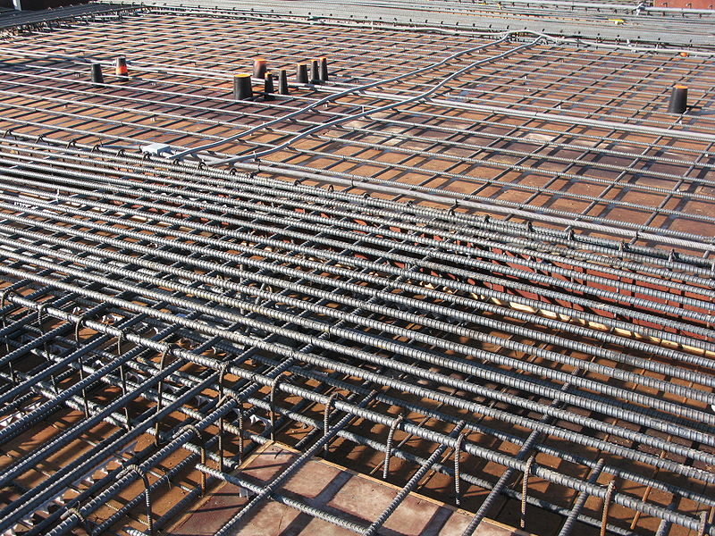
Traditional concrete structures consist of beams. Beams are structural elements whose duty is to transfer the loads applied to a slab, or plate to the supporting member. Where a concrete slab is very wide, beams are usually provided in-between to convert them into smaller panels. The dimensions of the beam required will depend on factors which vary between the span and the estimated load transferred to the beams from the slab.
Conventional drop beams are known to frequently interrupt floor clearance and impair the overall aesthetics of buildings. For example, consider where a beam is required to break up the wide slab panel at the interface of a lounge and dining of a residential dwelling, or where there is a line load from partitions on a wide slab panel. Adopting the conventional drop beam not only reduces headroom, but could impede the flow of electro-mechanical services and could ultimately be found not to be aesthetically pleasing. In such instances a CONCEALED BEAM is one of the possible solution available.
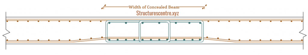
Concealed concrete beams are beams whose depth are kept equal to the thickness of supported slab. They are reinforced separately from the slab, having longitudinal bars and stirrups like a normal drop beam. Sometimes, they are referred to as “hidden or strong band beams” and are strictly provided in concrete slab as a result of the aforementioned concerns.
Concealed Beams vs Drop Beams
Contrary to certain opinion, the conversation around concealed concrete beams and the traditional drop beams have being reconnoitered a couple of times even before 2020 and result presented by several authors. (Mahmad and Raviz, 2017) in their study titled: Analytical study on Flexural behaviour of RCC slabs with concealed beams using ANSYS reported that the deflection of slabs supported with concealed beams was considerably more. This is to be expected, as a concealed beam is practically less stiff than a drop beam due to it reduced the depth.
(Akash and Teas, 2015) carried out a comparative study on the seismic performance of models with concealed beams and normal beams. The study reported that the displacement of the model with concealed beams was more compared to those of normal beams because the stiffness of a structure reduces with decrease in the sizes of the beams. Hence normal beams were recommended for designing building with seismic forces while concealed beams were endorsed for structures predominantly under gravity loading.
However, (Chetan and Hemant, 2017) in their research on the performance of concealed concrete beams recommended the use of concealed beams ahead of normal beams for buildings during earthquake excitation. The authors reported that although, the stiffness of the model with concealed beams was less, the base shear was significantly lesser, since the lesser the mass, the lesser will be the seismic force. The authors also posit in their conclusion, that in multi-storey structures, if long span slabs are present, they tend to deflect more. Thus, concealed beams can be provided in order to decrease the deflection and increase the stiffness of the slab.
By and large, from the perspective of strength and deformation, as evident in the literatures presented, the fact that a drop beam is better than a concealed beam cannot be contested. Away from strength and deformation, concealed beams are grossly uneconomical relative to drop beams due to the high quantity of steel often required to compensate for the insufficient effective depth and control deflection3. However, as earlier stated they are only required in certain instances, due to strict and very stringent architectural arrangement and requirements. They are highly unconventional, and their use within a structural system should be a judicious choice, involving in depth analysis within the overall context of structural behavior 4. Hence, nobody wakes up to concealing a concrete beam within a concrete slab, there must be sufficient reasons to justify their use.
Applications of Concealed Beams
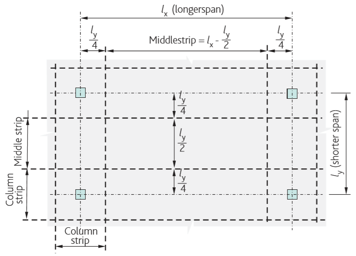
The idea of concealing a concrete beam originated from the concept of flat slabs and is only an extension of the concept1. Flat slabs are beamless slab, supported directly on columns without beams. A typical flat slab design, divides the slab panel into column strips and middle strips. The columns strips are slightly comparable to a concealed beam in terms of stiffness, they contain higher reinforcement than the middle strip due to moment distribution between the strips. Even where a load is applied directly on the middle strip, the bulk of the component from the positive moment is transferred to the column strip (See Table I.1 of BS-EN 1992-1-1). Hence the column strip is reasonably stiffer than the middle strip, and attracts more loads to itself, same way a concealed beam would be a stiffer zone in a concrete structure.
Generally, all advantages available to flat slabs are also available to concrete slabs that uses the concealed beam – increased headroom, clear way for electromechanical ducts, levelled soffits and typically enhanced aesthetic appearance of the finished building2. However, one of the most basic applications of concealed concrete beams is explained in the introduction of this article, which is to break up a wide interior panel into smaller sizes, where the use of the conventional drop beam is considered non-viable. Another application of concealed beams is as covered in the conference paper by (Liu and Zhang, 2020) where the authors opined that the provision of concealed beams in flat slabs without column head enhances the punching shear capacity and boost the structural integrity of the structure. The authors argued that weak connection is an inherent deficiency in flat slabs hence setting up a concealed beam is almost the only improvement method available.
Design of Concealed Beams
Designing a concealed concrete beam is the same procedure as the conventional drop beams, with the basic difference being that the beam depth must be restricted to that of the supported slab. This simply means that, the supporting slab might need to be sized conservatively in some instances, with the width of the beam very wide and heavily reinforced to compensate for the loss in stiffness and to control deflection which tends to be critical.
While a concealed beam is less stiff relative to conventional drop beams, it’s stiffer than a slab. The belief that, a concealed beam behaves like a slab, often stems from a stereotype that a beam must be considerably deep relative to its width in- order to behave like a beam. However, the behavior of a slab and a beam is no different, the distinction lies in stiffness which allows a slab to transfer its loads to the supporting member. Stiffness is not just a function of geometry alone but also strength. In terms of geometry, the IstructE technical guidance notes on concrete beam defines a concrete beam as an element having a width to depth ratio less than or equal to 5.
A concrete beam is an element whose width is less than 5 times its depth in other instances it’s a slab and should be treated as such
IstructE – Technical Guidance Notes on Concrete Beams
Even the most advanced codes of practice are silent on the geometry of structural elements in terms of cross-section, only their behaviour are emphasized. Thus, even from this perspective, a beam behaves just like a slab, they’re designed for flexure, shear and checked for deflection the same way.
As long as all rules governing the design of a concrete beam is followed and found satisfactory, the beam is able to achieve the requisite stiffness. This includes adhering to code span/depth ratios in order to control deflection. Although, deflection in concrete slab is a misnomer, with too many variables influencing the outcome, even the powerful FE models do not give an absolute answer. However, what we should do is always ensure that the deflection procedure follows the simple code checks.
Worked Example
Design Scenario
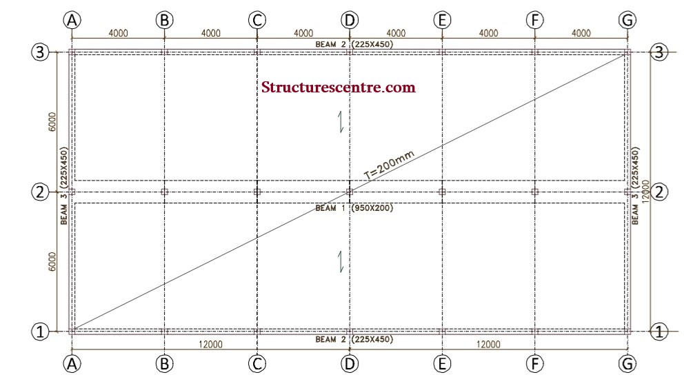
The designer of a reinforced concrete structure, having considered several factors at the conceptual design stage selected the solid slab construction as the most appropriate scheme for a structure. There is a requirement for two long slab panels at the first-floor to sustain line loads from permanent partitions at 4m centres in the x & y-direction. The use of any internal drop beams in both direction is considered non-viable.
Two schemes are proposed with the same material properties and subjected to the same loading conditions. And then investigated using Tekla structural designer software package.
Scheme 1
A one-way solid slab, with an internal drop beam, which in fact contradicts the brief by the provision of the drop beam along gridline 2, hence not a viable solution however, for the purpose of comparative study, this would be considered an alternative option. The line loads from the permanent partitions in the y- direction are applied directly on the slab.
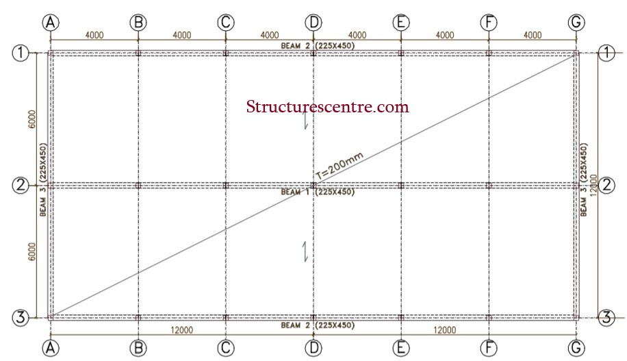
Scheme 2
A one-way solid slab with an internal concealed beams running along axis 2. Preliminary sizing of the concealed beam requires that span-depth ratio for the wide band beam is followed. However, in this case, it is in fact the span-depth ratio for the slab that controls. The line loads from the partitions, along the y axis are also applied directly on the slab.
Result from Analysis
The results obtained are the FEA results of the program.
Scheme 1
For scheme 1, with the one-way slab and drop beam along gridlines 2, the results are as follows- the main area of steel required at the bottom tension zone of the slab is (As, req = 884mm2) and the area of steel provided is Y12-100mm c/c (As,prov=1130mm2/m) to control deflection. At the continuous support the area of steel required is (As,req=1075mm2/m) and the area of steel provided is Y12-100mm c/c (As, prov=1130mm2/m). Y10-225mm c/c (As, prov=348mm2/m) was provided as the distribution bars.
The reinforcement provided in the tension zones of the drop beam is 4Y16mm bars at the endspans and 3Y16mm at the interior spans. At the continuous supports 4Y20mm is provided while at the end supports 2Y16mm is provided.
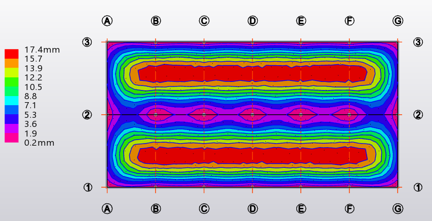
The maximum value of the long-term deflection for the entire plate, when subjected to the rigorous slab deflection analysis is 17.4mm ( See Figure 5).
Scheme 2
For the second case of the slab with concealed concrete beam, the areas of steel required in the slabs is closely the same. Hence, the same quantity of reinforcement provided as in scheme 1 is specified for scheme 2 as well.
The flexural reinforcement required at the bottom of the concealed beam to satisfy the deflection check is 9Y16mm bars at the end and interior spans while at the continuous supports, 14Y16mm is provided. At the end support 9Y16mm is provided.
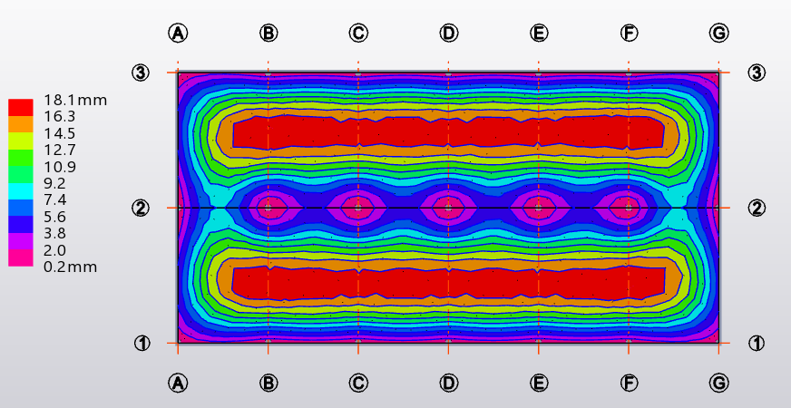
The maximum value of the long-term deflection for the entire plate, when subjected to the rigorous slab deflection analysis is 18.1mm. (See figure 6).
Discussion of Results and Conclusion
The result obtained from this study reinforces very quickly and succinctly summarizes some of the submissions made earlier. For instance, regardless of the fact that the concealed concrete beam in scheme 2 was heavily reinforced relative to the drop beam in scheme 1, the difference in the long-term deflections is absolutely meaningless and unimpressive. As earlier posited, the preference of a conventional drop beam to concealed concrete beams cannot be contested. Drop beams are not just structurally more efficient, but also economically better.
Scheme 2 is grossly uneconomical, despite a sizeable reduction in the volume of concrete required to construct beams. And one can almost doubt if there’s actually any benefit of concealing a concrete beam within concrete floors except that it respects the architecturally stringent brief. One can also argue that a flat slab, of equivalent thickness with ‘drop panels’ might’ve performed better, however, several factors would influence the selection of a scheme, occasionally the most economical scheme does not get selected either due to the expertise of the contractor, speed of construction or for some other logical reasons.
In conclusion, the design of concealed concrete beams should remain unconventional and should only be used when there’s a very strict and rigid requirement to justify their use. All rules governing the design of concrete beams apply including those on preliminary sizing.
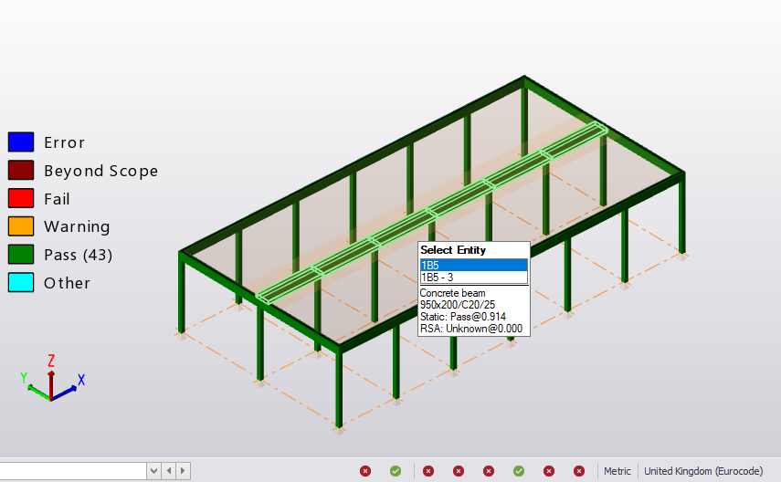
The calculation sheets for the drop and concealed beam can be viewed from the tab below.
Citations
- Akash.c. Arakere, Tejas D. Doshi, “comparison of Multy-storey buildings with Normal beams and concealed beams”. International research journal of engineering and technology, volume :02 Issue:03 June 2015.
- Chetan Talawar, Hemant Sonawadekar (2017), “Performance Based Analysis of Concealed Beam in Reinforced Concrete Structure”, Indian research journal of engineering and technology, Volume: 04 Issue: 06 | June -2017.
- Mahmad Irfan Nadagouda, G. Ravi (2017),” Analytical study on Flexural behaviour of RCC slabs with concealed beams using ANSYS”, International research journal of engineering and technology, Volume: 04 Issue: 07 | July -2017.
- Samir H. Helou, Muncher M. Diab, “Slabs with Concealed Beams Facts and Fallacies”. Asian Journal of Engineering and Technology (ISSN: 2321 – 2462) Volume 02 – Issue 04, August 2014.
- JingjingLiu, HaoyuZhang, “Common Design Problems and Optimization Measures for Flat Slab Floor Structures”, E3S Web of Conferences 143, 01033 (2020).
See: Designing a Concrete Beam to Eurocode
Postscript
There’s a need to write a caveat here, because there’s a stark distinction between a concealed beam as expressed in this article and the popular display in some construction sites, i.e., the “secret beam” as fondly called and purportedly believed to possess the same function as a concealed beam and provided in extremely thin slab. This has become a sort of obsession, especially in Nigeria’s construction industry. A concealed beam as expressed in this article must be sized according to the design requirements for beams, and where it has been designed, it’s heavily reinforced, this is contrary to what is seen in most construction site, as they’re merely reinforced with light bars. This would be an absolute disaster if the ‘secret beam’ were to be considered to perform the function of a principal structural element in the design.
The perceived importance of the ‘secret beam’ is that it stiffens a concrete slab against deflection, however, this cannot be explained within the context of concrete structures, hence their provision and use is a hoax.
Thank You!!!