This article explores the significance of bar schedules, the process of their preparation, and the nuances involved in their interpretation.
Accurate preparation and interpretation of bar schedules play a crucial role in the successful execution of structural engineering projects. Bar schedules, often associated with reinforced concrete elements, provide a detailed roadmap for the placement and configuration of reinforcing bars within structural components.
In the structural design process, the bar schedule is the last document produced for use during project implementation. In the structural design process, engineers typically identify and define the critical points where reinforcing bars are required. This process is informed by structural calculations, considering anticipated loads and stresses that elements will experience during their lifespan. Once the critical points are identified, the required size, shape, and spacing of the reinforcing bars can be determined.
Having determined the reinforcing bars details, these details are put into a drawing by a draughtman for implementation. However, structural drawings are sometimes too intricate and might not be easily interpreted by other members of the design team (for instance, by steel fixers during implementation). Hence the use of bar bending schedules. Bar bending schedules provides a detailed and organize plan for the placement of rebars in concrete elements.
By following the information outlined in a bar schedule, construction teams can ensure that reinforcing bars are correctly positioned within the concrete forms, promoting structural integrity, compliance with design specifications, and overall safety. The absence of clear and accurate bar schedules can lead to errors, compromise structural strength, and result in construction defects.
This article explores the significance of bending schedules, the process of their preparation, and the nuances involved in their interpretation.
Bar Scheduling
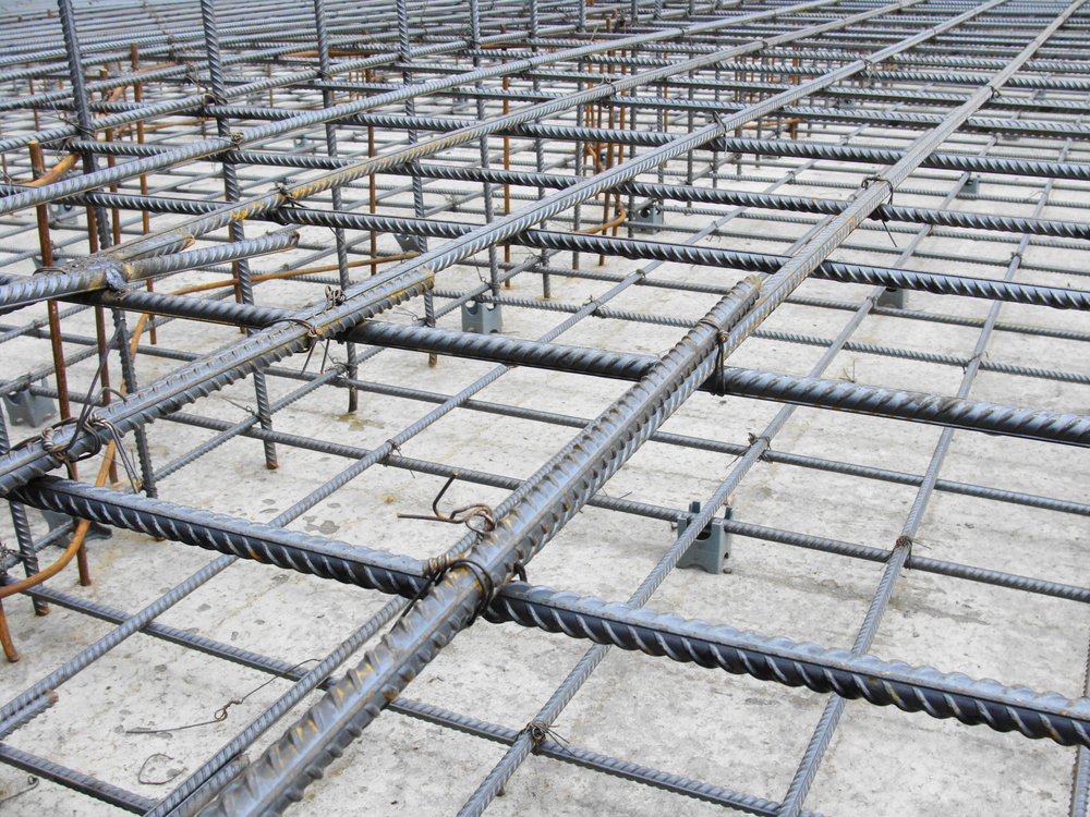
Scheduling is the operation of listing the location, mark, type and size, number off, length and bending details of each bar or sheet of fabric. When dealing with bars the completed lists are called ‘bar schedules.’ The bars are normally grouped together for each structural unit, e.g. beam, column, etc. In a building, the bars are listed floor by floor.
For cutting and bending purposes schedules are provided as separate A4 sheets and not as part of the detailed reinforcement drawings. Each schedule should be a document complete in itself, and references to earlier schedules by the use of such terms ‘as before’ or ‘repeat as 1st floor’ should not be allowed.
Schedules are used by the:
- detailer
- person checking the drawing.
- contractor who orders the reinforcement
- organization responsible for fabricating the reinforcement.
- steel fixer
- clerk of works or another inspector
- the quantity surveyor
Components of a Bar Schedule
BS 8666 is a British Standard. It provides specifications for the scheduling, bending, and cutting of steel reinforcement in concrete structures. A typical bar schedule (Figure) prepared to BS 8666 should contain the following key components:
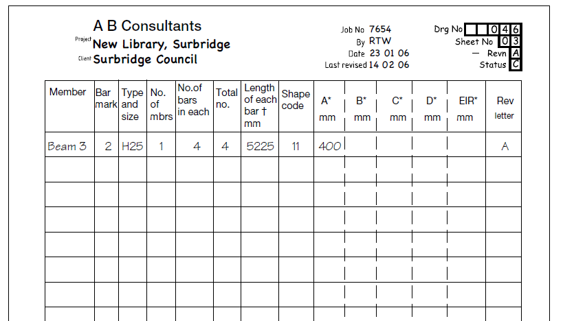
Member: Illustrates the specific element under examination, such as Beam 1, Column 1, or Column Type 2, and so forth.
Bar Size and Diameter: Indicates the diameter of each reinforcing bar, typically measured in millimeters. Different sizes are represented by numerical values, such as T10 for a 10 mm diameter bar.
Bar Number: Assigns a unique reference number to each bar for identification purposes and helps in cross-referencing the bar schedule with the structural drawings.
Quantity of Bars: Provides the total quantity of each type and size of reinforcing bar required for a particular element. Essential for accurate procurement and construction planning
Bar Shape/ Code: Specifies the shape of reinforcing bar, such as straight bars, bent bars, or special shapes. BS 8666 presents standard shapes of bars each of them identified by a unique shape code. Sometimes the shape code might be ignored, and the bar drawn on the schedule.
Bar Length: Specifies the length of each reinforcing bar, often measured in millimeters. Includes information on any special requirements, such as lap lengths or extensions.
Location and Position: Details the exact location and position of each bar within the concrete structure. Refers to grid references, column lines, and other designations to guide placement.
Steps of Preparing Bar Schedules
The following procedure can be generally adopted in preparing bar schedules.
Refer to Design Drawings: Refer to the design drawings provided by the structural engineer. These drawings will typically include details on the required steel reinforcement for each structural element.
Identify Reinforcement Types: Determine the types of reinforcement required for each concrete element. This includes main bars (longitudinal bars) and distribution bars (stirrups or ties).
Include Bar Marking: Assign a unique bar mark to each bar for identification purposes. This mark should be referenced in both the Bar schedule and the design drawings.
Calculate Quantities: Calculate the quantity of steel reinforcement required for each element based on the design drawings and specifications. Pay attention to bar sizes, spacings, and lap lengths.
Prepare the Bar Schedule (BS): Create a bar schedule for each type of reinforcement. Include information such as bar mark, shape code, dimensions, cutting length, bending details, and quantities.
Check Compliance with BS 8666: Ensure that the prepared bar schedules comply with the specifications outlined in BS 8666. Verify bar sizes, shapes, spacings, and lap lengths against the standard.
Document and Revise as Needed: Document the final bar schedules and any revisions made during the coordination process. Ensure that all parties involved have access to the updated information.
Guides in Preparing and Interpreting Bar Schedules
Schedules should have simple consecutive reference numbers not exceeding six characters and should be cross-referenced to the relevant drawing number. Such terms as page number, sheet number, etc., can be confusing and are not recommended. A convenient way of achieving this is to use the first three characters to refer to the drawing number (implying that the project will be divided into units with a maximum number of 999 drawings per unit), to use the next two characters to describe the schedule number (starting at 01 and not exceeding 99 schedules per drawing), and to reserve the last character for revision letters. If an internal job number or other internal reference number is used, it is suggested that this should be incorporated in the site reference, rather than extending the reinforcement schedule reference.
The form of bar and fabric schedule and the shapes of bar used should be in accordance with BS 8666. The preferred shapes of that Standard account for more than 95% of the reinforcement that is used. It is preferable that bars should be listed in the schedule in numerical order.
Also, it is essential that the bar mark reference on the label attached to a bundle of bars refers uniquely to a particular group or set of bars of defined length, size, shape and type used on a job. This unique reference is achieved by a combination of the bar schedule reference number and the bar mark number. (To comply with BS 8666, both the schedule reference number and the bar mark must appear on the label attached to the bundle of bars).
The bar size is not part of the bar mark, and prefixes or suffixes of letters or other characters to describe the location of the bars should not be included in the bar mark. The exception to this rule is when bars of varying shape or length are used and are described on the drawing thus:
8H20-1(a to h)-150
The bar mark given on the schedule is therefore 1a, 1b, 1c.
On a small job with only a few drawings it may be convenient to start at bar mark 1 and carry on through the whole job in a consecutive sequence. On larger jobs it may be more convenient to start scheduling each drawing with bar mark 1, relying on the site to distinguish between mark 1 on drawing 1 and mark 1 on drawing 2.
When top and bottom reinforcement are detailed on separate drawings it is advantageous to allocate a group of bar marks for each drawing, e.g. bottom reinforcement bar marks 1-99, top reinforcement bar marks 100-199. And when it becomes necessary to revise a bar item on the schedule or drawing both the drawing and schedules should be re-issued.
Also See: Structural Drawing Connotations and Interpretation
Sources & Citations
- The Institution of Structural Engineers (2006) Standard Method of Detailing Structural Concrete. 3rd ed. London: The Institution of Structural Engineers