There are four key aspects of masonry cladding to steel-framed buildings that is vital before developing an interface between masonry and steel frames.

Since the invention of medium storey framed structures in the late 1800s, there has been a need to clad them with a reasonably robust material that acts as an efficient barrier to the external environment. Masonry delivers the performance required of a cladding system on multiple fronts. It has therefore developed from a load-bearing element within structures to become a component of an envelope to larger framed buildings.
This article aims to guide structural engineers through the crucial interfaces between a steel-framed primary structure and a masonry cladding system.
There are four key aspects of masonry cladding to steel-framed buildings is very vital before developing an interface between masonry and steel frames. These are:
- Methods of Support (Both Vertically and Horizontally)
- Movement of Masonry
- Movement of Supporting Elements
- Corrosion Prevention
Any successful masonry-based cladding system must address these aspects to prevent failure. Failure can occur immediately after construction due to inadequate support methods or over the building’s lifespan due to corrosion.
This article therefore will therefore address each aspect, demonstrating their interdependence in creating an effective system. For a discussion on the material properties of masonry, refer to the previous article, “A Background to Masonry Design to Eurocode 6.”
Methods of support
Unlike curtain wall cladding systems, masonry is heavy and brittle, making it very sensitive to movement of the supporting structure. Masonry cladding therefore needs robust connections to the primary structure that will allow the envelope to expand and contract during the building’s lifetime.
Geometry is a very important factor when developing a support system for masonry cladding. Complex shapes may be formed with the cladding and consideration must be given to how accurately it will be installed. In any cladding interface with a primary structure, the level of accuracy within the cladding system is typically different to that of the structure it is enveloping.
For masonry cladding systems, it is considered best practice not to specify tolerances or movement greater than those stipulated within the building’s design documentation. In the UK, this is normally the guidance given in the National Structural Steelwork Specification (NSSS). This allows the specialist installer to use methods they have developed over many years to counter the variances from the defined datum within the steel frame.
Direct lateral restraint is provided by the frame on a floor-by-floor basis, but vertical support is intermittent. This reduces the cost of installing proprietary support systems, which are typically expensive (Figure 1).

An alternative is to support masonry cladding off a sub-frame that is fixed to the primary structure. This allows cladding brackets to be aligned as required for the masonry units within the cladding, which may not coincide with the ideal place to fix to the primary structure. A comparative explanation of these support methods is given in Table 1.
| Fixing Type | Advantages | Disadvantages |
| Cast-in fixings to floor slabs | Fast installation and robust support system | Reliant on coursing to masonry to match fl oor slab |
| Proprietary support angles to primary structure | Less reliant on coursing to masonry cladding matching location of line of support | Can cause torsion to primary steel elements and increase complexity of fi xing of angle supports to structure |
| Sub-frame supported from primary structure | Designed for single purpose of supporting masonry with primary structure acting as anchor/foundation | Slightly more expensive than other more direct support methods and requires close coordination with primary frame design |
Due to the high vertical loads that masonry cladding imposes onto the primary frame structure, it is possible that a significant eccentric load will be applied onto the perimeter beam of a frame. This can lead to torsional effects, as described in an earlier article (See: Avoiding Torsion in Structures). To counter this issue, a closed steel section can be used to support the masonry. These are resilient to torsion but are not as stiff as open steel sections of a similar depth. They therefore have greater vertical deflections that cannot easily be accommodated by the masonry cladding. It is recommended to detail the support system in such a way as to avoid significant torsional effects onto the perimeter steel beams.
Lateral restraint to masonry cladding is typically provided by wall ties attached to the primary superstructure. These can be cast in where there is a concrete floor edge and/ or fixed directly to the steelwork. The latter method of fixing requires careful consideration due to the high moisture content these ties are exposed to; the connection to the mild steel frame element is typically the weakest point. Table 2 describes the three most common methods for fixing wall ties to masonry into the primary structure.
| Fixing Type | Advantages | Disadvantages |
| Bolted through steel element | Robust fixing that creates positive and resilient connection between wall tie and steel element | Sensitive to tolerance of verticality of wall ties versus primary structure. May require vertically slotted holes to overcome this within steelwork |
| Self-tapping screws | Easy to install and provide reasonably robust connection to steel elements | Rely heavily on good workmanship on part of installer |
| Proprietary slotted fixings | Pre-installed onto steel and slotted confi guration makes them less sensitive to vertical tolerances | Expensive when compared to other fi xing methods and can be damaged during transportation of steel elements they are fi xed to |
In-plane Movement of Masonry
Masonry cladding panels experience in-plane movement due to thermal variances and moisture ingress. Thermal effects arise from temperature changes, while moisture can be absorbed from the air or rain. Clay and concrete, the primary materials for masonry, respond differently: clay expands over time, whereas concrete shrinks.
To prevent stress buildup from planar movement, horizontal and vertical movement joints are necessary. Thin-wall cladding systems, unlike thicker load-bearing masonry, cannot distribute induced stresses effectively and thus require these joints.
The cladding specialist typically determines the layout of movement joints, and the structural engineer designs support systems that accommodate these joints. The cladding panel design must also consider support conditions created by the movement joints. In the UK, this design follows BS EN 1996-1-1, assuming lateral support conditions are either simply supported or absent, depending on the movement joint type. Panels must also withstand horizontal wind actions as defined in BS EN 1991-1-4.
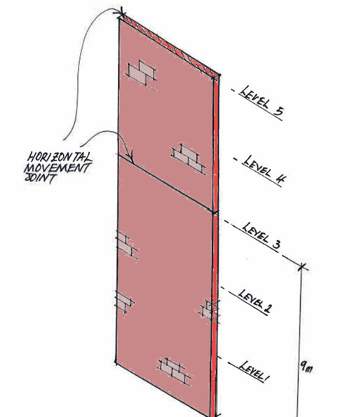
Horizontal movement joints in multistorey masonry cladding should be spaced no more than three floors or 9m, whichever is less, from the ground level, with additional joints required every other floor above the third level. For buildings under 12m tall, horizontal movement joints are unnecessary (Figure 2). Vertical movement joints, according to BS EN 1996-2, Cl. 2.3.4.2, should be placed at 10–12m intervals, with a maximum of 15m if mortar beds are reinforced (See Table 3).
| Movement joint spacing (m) | Joint widths (mm) |
| 0-7 | 10 |
| 7-11 | 15 |
| 11-15 | 15-20 |
Vertical movement joints in masonry cladding are usually left open, with a waterproof membrane behind the cladding acting as a barrier against moisture ingress. In cavity walls, different materials (e.g., clay bricks and concrete blocks) are used for the two skins, requiring flexible wall ties to accommodate differential movements caused by environmental factors. Vertical joints are staggered between the two skins to prevent overstressing the ties.
Movement joints must be coordinated with support systems. For instance, a vertical movement joint in a masonry wall supported by a proprietary angle cannot have the angle continuous through the joint, as this would restrict in-plane movement. Finally, joints must not compromise the lateral stability of masonry panels, even though they may create a visually undesirable patchwork appearance. Careful planning of joint placement is crucial to maintain the aesthetic integrity of the cladding.
Displacement of Supporting Structural Elements
Masonry cladding is particularly sensitive to movement in the primary structure it is attached to, especially when cement-based mortar is used, as this decreases the wall panel’s flexibility. Structural engineers must exercise extra caution when designing support systems for masonry cladding. Standard design rules for steel elements regarding relative vertical deflections are not applicable here.
Typically, a floor-supporting beam has a vertical deflection limit of span/360 or 20mm, whichever is less, under variable action. For instance, a 6m beam supporting a 150mm concrete floor slab has a maximum allowable deflection of 17mm. However, for a beam supporting a masonry wall, 17mm is excessive and would likely cause the wall to crack as the beam deflects.
Therefore, it is best practice to limit vertical deflections of beams supporting masonry to no more than 5mm or span/500, whichever is less, under all applied actions, including the cladding’s weight. Meeting these stringent deflection limits might necessitate changes to the primary structure, such as adding more columns. Though challenging, adhering to these limits is crucial to prevent the masonry cladding from cracking and becoming unstable.
Horizontal sway also demands stricter control due to how masonry cladding responds to primary structure movements. For buildings up to six storeys, the recommended limit is height/300 per storey. For buildings nearing 20 storeys, the limit reduces to height/600 per storey. At this height, height/300 equates to approximately 200mm, an excessive sway for masonry cladding. The reduced limit ensures stability.
The final form of movement to consider between the steel frame and masonry cladding is the differential movement. Clay masonry walls tend to expand vertically more than the steel structure, causing relative movement in all directions. Wall ties must be designed to flex, accommodating the differential movement without restraining the masonry. This prevents stress buildup within the wall panel, which could otherwise lead to cracking.
Corrosion Prevention
Corrosion of wall ties, which provide lateral support to masonry cladding panels, is a primary cause of failure in masonry cladding systems. Older masonry-clad buildings are especially susceptible to this, often requiring significant repairs and replacement of wall ties.
In contemporary masonry-clad systems, corrosion is triggered by an electrolytic or bimetallic interface between wall restraints, supports, and the mild steel primary frame elements. Wall ties and support angles are typically made from stainless steel due to their exposure to moisture. The porous nature of masonry allows water to seep through into the space between the cladding and the primary structure, creating a moisture-rich environment that, without proper ventilation, can quickly lead to corrosion.
To prevent this, an isolating layer is placed between the stainless-steel wall ties and supporting elements and the mild steel beams. This usually consists of plastic bushes, gaskets, and washers, which serve as inert barriers between the two metals.
Steelwork within the external cladding envelope, providing direct restraint and support to the masonry, requires substantial corrosion protection. In the UK, the Steel Construction Institute (SCI) advises applying C1, C2, and C3 categories of corrosion protection, ensuring no direct contact between the masonry and the mild steel frame elements.

As masonry inevitably cracks and leaks over time, provisions must be made to drain water away from the steelwork to the masonry’s outer face. This is typically achieved by incorporating gaps in the masonry units to create discreet weep holes for moisture drainage (Figure 3).
Also See: Designing a Masonry Retaining Wall | Worked Example
Sources & Citations
- Brick Development Association (2014) Movement joints: Provision of brickwork expansion joints, London: BDA
- C. O Regan (2017) Masonry Cladding to Steel-framed Buildings. Technical Guidance Note 13(level2). The Structural Engineer 100(10).