This article highlights the historical shift of masonry from structural to cladding element, emphasizing modern applications and considerations based on Eurocode 6
Historically, masonry can be regarded as one of the earliest construction methods. It’s use dates back to antiquity. There is evidence of the use of some form of stone masonry originating over 10,000 years ago. In Mesopotamia and Egypt, mud bricks were meticulously stacked and reinforced with reeds to construct homes, temples, and fortifications. Similarly, the Greeks and Romans utilized stone and mortar to erect iconic structures like the Parthenon and the Colosseum, showcasing the versatility and resilience of masonry construction.
However, over the course of the last century, masonry has become less common as a structural material, largely because steel and concrete frame construction became more popular. Since concrete and steel frame are relatively lighter.
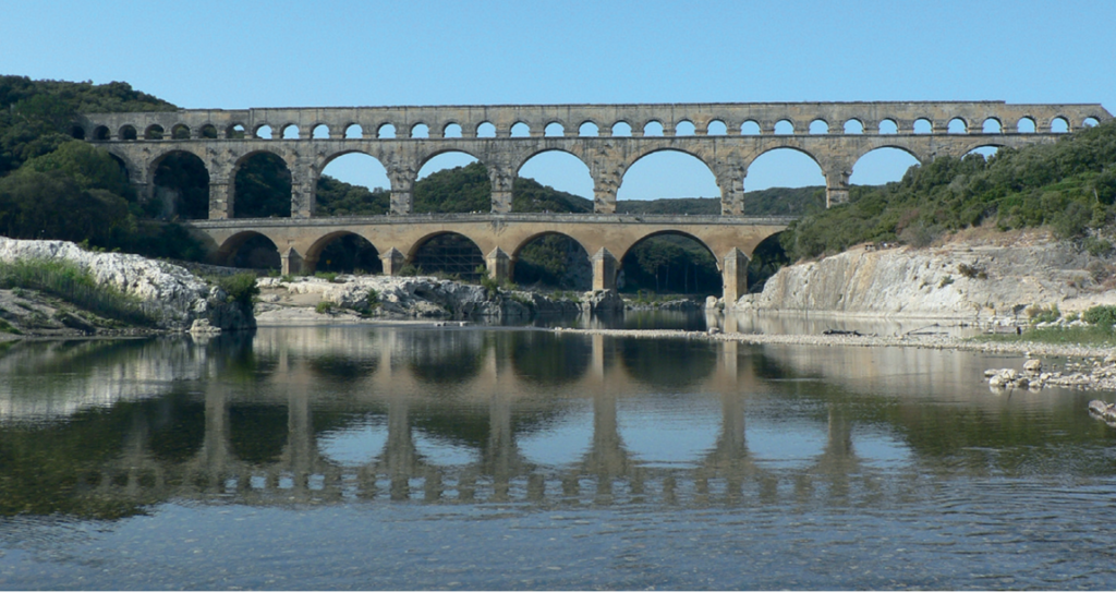
In response to this shift, masonry has been relegated to primarily serving as a form of cladding, especially for concrete and steel framed structures. In the UK, the prevalence of wind-driven rain has led to widespread adoption of cavity wall construction. This means that each layer will be relatively thin, necessitating careful consideration in design alongside the load path for wind-induced actions. However, load-bearing structural masonry remains in use and is utilized in constructing low-rise buildings and soil retaining structures, as it has been for centuries. The enduring durability of masonry is vividly demonstrated by the Pont du Gard, a Roman aqueduct constructed entirely from stonemasonry, which still stands almost 2,000 years after its completion (See article featured image.
This article highlights the historical shift of masonry from structural to cladding element, emphasizing modern applications and considerations based on Eurocode 6
Guides to Masonry Design to EC6
Blocks Vs Bricks
The three primary forms of masonry are brick, concrete block, and stone, with this text focusing mainly on brick and block due to their prevalent use. Bricks, typically crafted from clay with added sand to minimize shrinkage while drying, undergo firing in kilns at temperatures surpassing 900ºC post-drying.
Concrete blocks are created using a specific concrete mixture containing aggregate particles no larger than 5mm. This mixture also includes a significant amount of sand to minimize shrinkage during curing. Lightweight concrete blocks, alternatively, feature aggregate in the form of sand and are composed of a mixture containing expanded clay, shale, or slate. During the curing process, these materials expand, resulting in a lighter block with dimensions comparable to medium or dense concrete blocks.
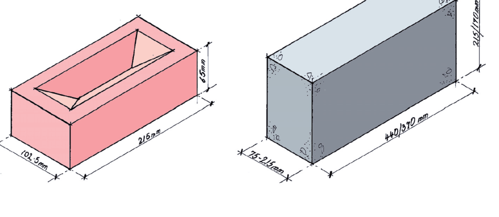
Modern bricks, depicted in Figure 1, are manufactured in standardized sizes, influencing the arrangement of interacting elements. Traditionally, concrete blocks measure 440mm x 215mm; however, modern blocks come in a broader range of sizes. This expansion is primarily driven by the need to restrict the weight of units requiring manual handling.
Clay bricks exhibit different absorption levels, determined by their manufacturing process and mix composition. They are categorized into three groups based on their moisture absorption capacity: less than 7%, between 7% and 12%, and more than 12%. These absorption levels affect the flexural strength of masonry, with the most absorbent bricks being the weakest.
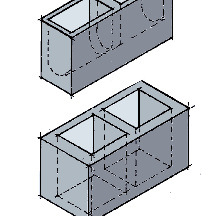
Concrete blocks may feature cavities formed using void formers installed during curing. Those with cavities not extending through the block’s full depth are termed cellular blocks. Due to their lighter weight, larger block sizes are feasible, as they are easier to lift and position. Blocks with voids extending through their entire depth are known as hollow blocks, and it’s common to incorporate steel reinforcing bars threaded through them, as depicted in Figure 2.
Mortar
Mortar acts as the bonding agent for masonry, typically 10mm thick, although it can be as thin as 0.5mm. Originally clay-based, mortar evolved into a lime and sand-based mixture used until the early 20th century when cement-based mortar became prevalent.
The switch to cement-based mortars occurred due to their reduced weather dependency during construction and rapid early strength gain, expediting the building process. However, cement-based mortars lack the self-healing properties of lime-based ones, requiring greater attention to movement. Additionally, they force moisture in the wall to evaporate from the brick face rather than the mortar, potentially damaging the brick surface.
When working on historic structures, it’s crucial to use appropriate mortar, often a requirement for approval from the local Historic Buildings department. The UK National Annex to BS EN 1996- 1-1 Design of Masonry Structures categorizes mortar into four classes: M2, M4, M6, and M12. The lower the class number, the weaker and more flexible the mortar. Class M12 has a compressive strength of 12 N/mm2 and is brittle compared to Class M2 with a strength of 2 N/mm2, yet it is the most flexible of cement-based mortars. Class M4, with a compressive strength of 4 N/mm2, is the most commonly used mortar as it offers sufficient flexibility without sacrificing compressive strength
Movement
Masonry undergoes changes in response to fluctuations in moisture content and temperature. Initially dry when manufactured, brick masonry gradually absorbs moisture from the atmosphere over time, causing it to expand. Conversely, concrete blocks, like all concrete materials, experience initial shrinkage as their moisture content decreases to match atmospheric conditions. Following this initial movement, masonry’s moisture content fluctuates with the seasons, resulting in seasonal variations in size. Both brick and concrete masonry are also subject to size changes due to temperature fluctuations, with clay masonry typically exhibiting a slightly lower coefficient of linear thermal expansion compared to concrete masonry.
In terms of construction limitations, clay brick walls can typically span up to 15m horizontally without requiring vertical movement joints, although joints are commonly placed at 12m intervals. Concrete block walls experience initial shrinkage and have a slightly higher temperature coefficient, necessitating vertical movement joints spaced at a maximum of 9m, although 6m spacing is more common. Stone masonry, with its minimal initial movement, only requires consideration of seasonal moisture and thermal movements, thus necessitating joints every 20m.
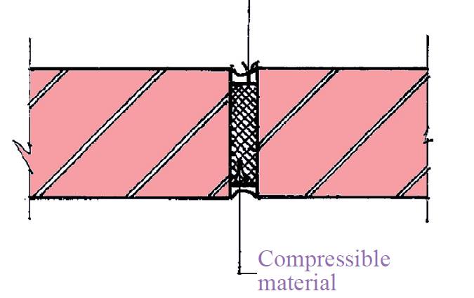
Vertical movement joints, typically comprising a gap of 10-20mm (Figure 3) filled with compressible material and sealed with mastic to prevent water ingress, are essential. To be effective, these joints must lack continuity across them, remaining unrestrained. The spacing of joints can be influenced by panel proportions and the presence of openings, both of which should be taken into account when determining joint positions.
Bonding
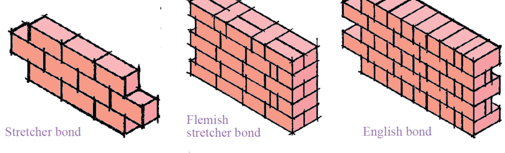
Masonry offers versatility in patterns, accommodating different levels of strength and complexity. Among the most prevalent patterns are the Stretcher bond and Flemish bond variants, as depicted in Figure 4. A wall constructed in two layers with joints parallel to the wall face is termed a ‘collar jointed wall,’ which influences the wall’s strength. Cavity walls consist of a single skin with a gap between them. When the two walls are interconnected using wall ties, both layers contribute to the wall’s composite action.
Exposure conditions and moisture content
The projected exposure conditions greatly influence the durability of new masonry. Water ingress can weaken the material and is a crucial factor to consider in design. BS EN1996-2, which covers the Design of Masonry Structures, provides guidelines for addressing this issue and categorizes exposure conditions into five categories: MX1, MX2, MX3, MX4, and MX5. MX1 represents the most inert environment, while MX5 represents the most extreme. Table 1 outlines the classification of these exposure conditions, providing clarity on their respective characteristics.
| Class | Exposure Condition | Example |
| MX1 | Dry environment | Interior of buildings and external masonry that has been rendered and is not exposed to driving rain |
| MX2 | Exposed to moisture or wetting but not freeze/thaw action, especially below ground sulphates and other aggressive materials | Interior of buildings with high humidity, masonry covered with overhanging roofs and external walls not exposed to driving rain. External walls that are not exposed to chemicals and with cappings that provides some protection |
| MX3 | Exposed to wetting and freeze/thaw action | Similar to MX2 only with freeze thaw action |
| MX4 | Exposed to salt water and/or saturated salt air | Masonry within coastal areas and buildings close to roads that are salted during the winter |
| MX5 | Exposed to aggressive chemicals | Masonry subject to aggressive chemicals e.g. below ground masonry, retaining walls in contact with sulphate bearing soils and masonry near some industrial buildings |
Guidance on the specification of masonry for a particular exposure class is given in Table 15 of PD 6697: Recommendations for the design of masonry structures to BS EN 1996-1-1 and BS EN 1996-2.
This article has been an introduction on the design of masonry structures to Eurocode, watch out for future guidance.
Also See: Designing a Masonry Retaining Wall| Worked example
Sources & Citations
- Morton J. (2011) Designers’ Guide to Eurocode 6: Design of Masonry Structures: EN 1996-1-1 London: Thomas Telford Ltd
- Institution of Structural Engineers (2013) ” Introduction to Masonry” Technical Guidance Notes (Level 1). The Structural Engineer 95(6) pp 24-26.