This article provides an overview of the rules applicable when detailing foundation to Eurocode. It covers pad footings, ground beams, raft foundations and piling.
No foundation design is complete without detailing the foundation. Detailing, which involves translating the design process into drawings for implementation, ensuring alignment with design intent and constructability which is just as important as the foundation design itself. The Eurocode serves as the preeminent guide, providing meticulous standards for designing and detailing various foundation types, including pad foundations, ground slabs, ground beams, and rafts. These guidelines, enshrined within the Eurocode, cover crucial aspects such as selecting concrete grades, specifying nominal cover, determining reinforcement spacing, and establishing tailored rules for different foundation configurations. Adhering to Eurocode guidelines ensures not only compliance with regulatory standards but also optimizes structural performance, durability, and safety across a broad spectrum of construction projects.
The emphasis Eurocode places on concrete grade, nominal cover, reinforcement spacing, and specific detailing rules highlights the imperative of meticulous design and execution in foundation engineering. From establishing the requisite strength of concrete to outlining the minimum cover over reinforcement bars, Eurocode’s comprehensive provisions aim to safeguard structures against corrosion, environmental factors, and other potential hazards. By exploring the intricacies of foundation detailing to Eurocode standards, engineers can unlock the keys to robust, resilient infrastructure that withstands the test of time, bolstered by a meticulous adherence to internationally recognized best practices in structural design and construction.
The information given in this article relates to:
- Rectangular pad footings and combined-column bases
- Piled foundations
- Rafts
- Ground beams and slabs.
The specification of joints and water bars for water resistant structures are not covered in this article. However, Reference could be made to CIRIA Report 139, Water-resisting basements.
Design and Detailing Notes
Concrete Grade
Concrete grades lower than 28/35MPa (cylinder strength/cube strength) are not normally used for foundations, unless there is a specific durability requirement (e.g. for concrete grade/mix in contaminated ground).
Nominal cover to all reinforcement (EC2, Clause 4.4.1.3)
- Large foundations, pile caps, pad and wall footings: 75mm
- Bottom cover for piled foundations: 100mm. The extra cover recognizes that piles project into the cap and the reinforcement mat is laid on them.
- Earth face: 45mm + Δcdev
- External exposed face: 35mm + Δcdev (other than earth faces).
- Internal face: (25mm or bar size) + Δcdev, whichever is the larger. This refers to the top of ground slabs, inside trenches, etc.
Note: There may be particular requirements for concrete grade/mix in contaminated ground.
Minimum Area of reinforcement (EC2, Clause 9.2.1.1)
Tension reinforcement: The minimum area of steel according is given by Clause 9.2.1.1
A_{s,min} = 0.26 bt d \frac{f_{ctm}}{fyk}\quad or\quad 0.0013 bt dwhere:
- bt is the mean width of the tension zone
- d is the effective depth
- fctm is determined from Table 3.2 of EC2
- fyk is the characteristic yield strength
For concrete Grade 28/35 and fyk = 500 MPa
A_{s,min} = 0.0014 bt dBar diameters less than 16mm should not be used except for lacers.
Bar spacing (EC2, Clause 9.8)
- Minimum spacing – 75mm (bars 40mm sizes and greater: 100mm)
- Pairs of bars: 100mm
- When considering the minimum spacing of bars of 32mm size or greater, allowance must be made for lapping of bars.
- Maximum spacing: 200mm
- Minimum spacing: 100mm
- Maximum spacing
- When Ast is 0.5% or less – 300mm; Between 0.5% and 1.0% – 225mm; 1.0% Ast or greater – 175mm
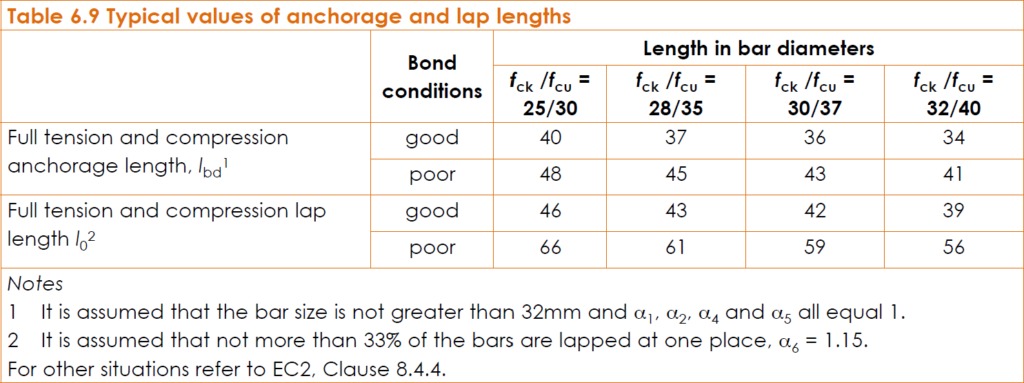
Anchorage and lapping of bars (EC2, Clauses 5.2.2, 5.2.3 and 5.2.4)
For 500 Grade steel Figure 1 gives typical anchorage and lap lengths for ‘good’ and ‘poor’ bond conditions.
Lap lengths provided (for nominal bars, etc.) should not be less than 15 times the bar size or 200mm, whichever is greater. Starter bars for columns should have a minimum horizontal leg of 450mm to ensure that the compression forces can be transmitted to the foundation, unless it can be shown that the column is lightly loaded and that the design compressive stress in the bars is less than 50% of its maximum capacity.
Detailing of Foundations
Pad footings and column strips
Straight bars are normally used without curtailment, and should be detailed if nothing else is specified (see Figure 2). However, an anchorage length should be provided from the face of the wall or column to the end of the bars. This may require bobs to be bent at the ends of bars. If lx > 1.5 (cx + 3d), at least two-thirds of the reinforcement parallel to ly should be concentrated in a band width (cx + 3d) centered at the column, where d is the effective depth, lx and cx are the footing and column dimensions in the x-direction and ly and cy are the footing and column dimensions in the y-direction. The same applies in the transverse direction with suffixes x and y transposed.

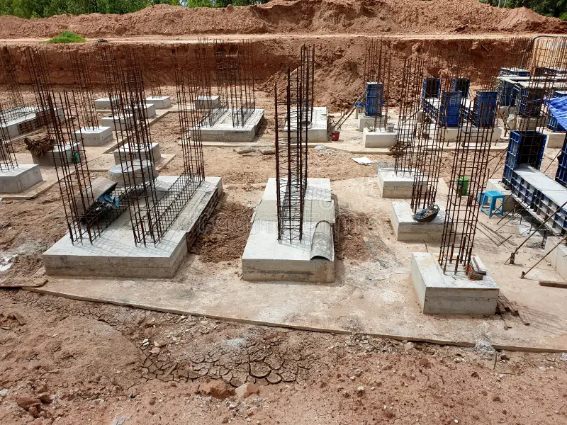
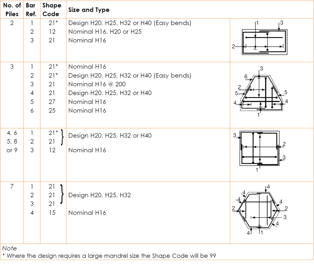
Pile Caps
A full tension anchorage length should be provided from the centre line of the edge pile to the end of the bar. The configuration of reinforcement that is normally adopted for standard pile caps is shown in Figure 3.
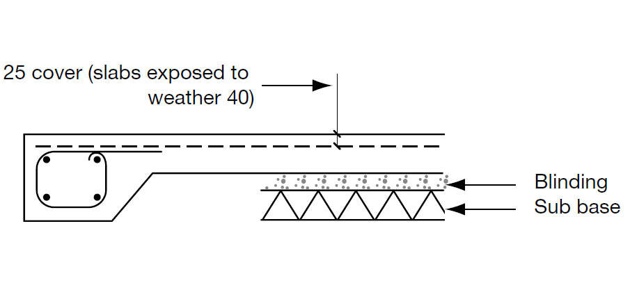
Ground Slabs
This clause refers only to lightly loaded ground slabs, typically in buildings. Where such slabs are cast directly onto the ground, they should be reinforced to control cracking (See: Design and Detailing of Ground Bearing Slabs). Square mesh fabric (A193) is suitable for this purpose. Laps of 300mm minimum should be used (see Figure 4). Details for fully reinforced slabs are given separately in 6.2 of these manuals.
Ground beams
Detailing of ground beams is dealt with in the same manner as typical floor beams, except that the cover to reinforcement should be increased to 75mm where formwork is not used. Where ground beams span on to pad footings or pile caps which otherwise would not require top steel, the main beam reinforcement should be continued right across the foundation. When the ground beam is used as a tie between foundations, the main beam reinforcement should pass around the column or wall starter bars and be fully anchored (see Figure 5).

Rafts
Detailing reinforcement in rafts follows the exact same rules as typical floor slabs. However, detailing a raft is more dependent on the construction method and sequence. Thus, a designer should always give clear instructions which relate to a possible solution. These instructions should be confirmed with the contractor before detail drawings are produced and should include:
- Position of construction joints for lapping of reinforcement
- Position, width and depth of movement joints
- Position of water bar joints.
In order to avoid congestion of reinforcement, consideration should be given to adding splice bars at lapping points and placing them in a separate layer.
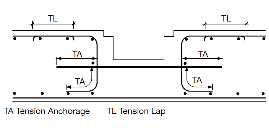
Ducts and Trenches
Where ducts and trenches occur in ground slabs (see Ground slabs), if there is no requirement for design reinforcement, nominal reinforcement should be placed around them (see Figure 6).
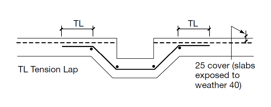
Where they occur in rafts or multi-column foundations, special attention should be given to detailing continuity top reinforcement, where moment transfer is required (see Figure 6).
Normally walls for small trenches and manhole chambers should be detailed with a single layer of reinforcement in each direction.
Column And Wall Starters
Wherever possible column and wall starter bars should be specified with the footing reinforcement and care taken to define their position relative to the column section or wall.
Chairs (BS 7973)
Where top reinforcement is required in multi-column foundations and rafts, consideration should be given to the method of supporting this with chairs and edge U-bars. This should take into account the construction sequence, the weight of top reinforcement and depth of foundation, which affect the size and number of chairs required. The concrete may be poured in more than one layer, and it may thus be possible to sit the chairs on an intermediate level.
Detailing Information
Design information for detailing should include:
- Layout drawings including column and wall outlines.
- Plan dimensions including depth and level.
- Dimensions and positions of kickers (standard kicker height below ground 150mm, above ground 75mm).
- Concrete grade and aggregate size (standard 30/37MPa and 20mm).
- Cover to reinforcement (standard 75mm; bottom cover for piled foundations 100mm). Position in plan of starter bars.
- Reinforcement parallel to x axis and parallel to y axis, clearly relating to layout drawings. This should include:
- Number and pitch of bars Type of reinforcement and bond characteristics (standard H)
- Diameter of bars and direction of bottom bars If standard pile cap number of piles (see standard arrangements in 6.7.2).
- Reinforcement for starter bars and links. This should include:
- Number and position of bars
- Type of reinforcement and bond characteristics.
- Band width details of reinforcement when required.
- Details of L-bends. These are only required if anchorage length necessary exceeds the length between the face of the column or wall and the edge of foundation.
- Details of construction joints
- Details of gullies etc. which affect slab detail.
Also See: Detailing a Concrete Column to Eurocode 2 | Worked Example
Sources & Citation
- The Institution of Structural Engineers (2006) Standard Methods of Detailing Structural Concrete- A manual for best practice (Third Edition) London: The Institution of Structural Engineers.