This article highlights the design of strap foundations: a very viable solution where the position of a column with respect to its foundation must be eccentric as a result of site constraints.
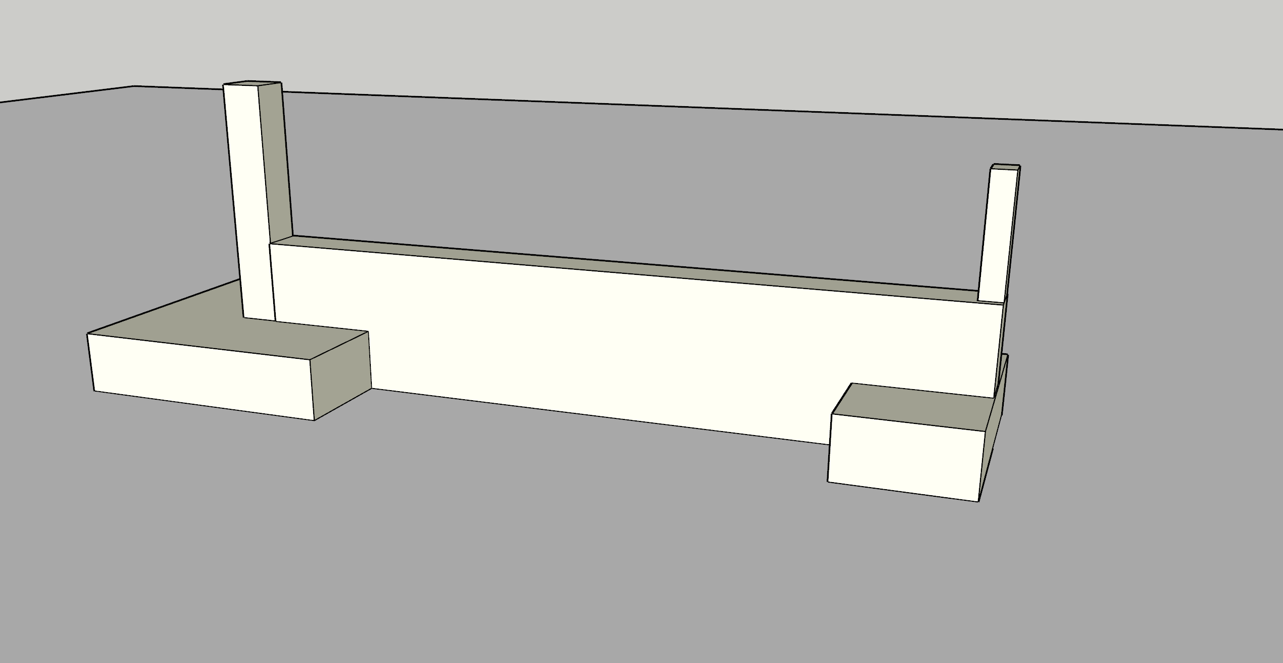
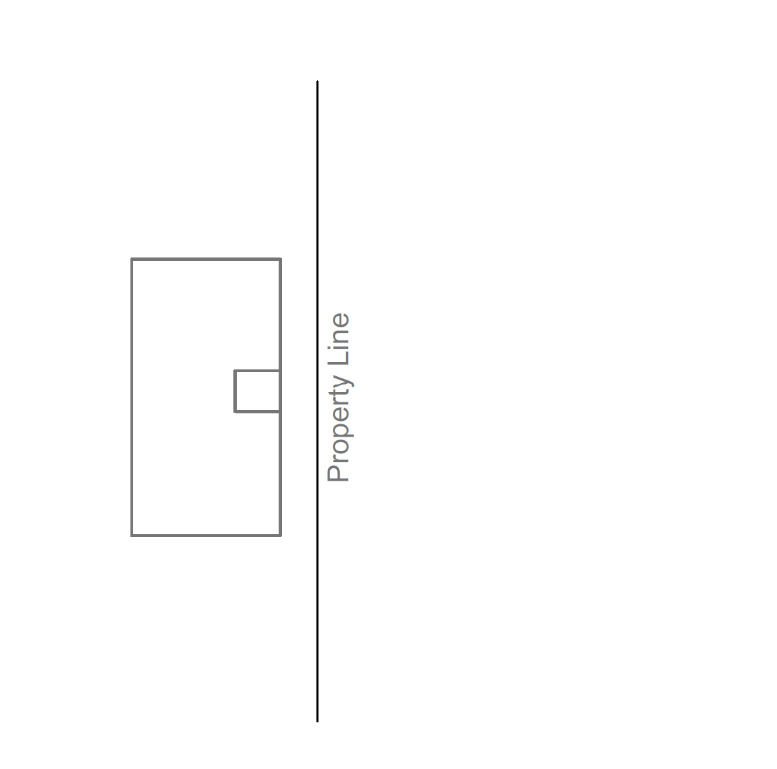
Strap foundation belongs to the family of spread foundation. It is very useful solution where the base for an exterior column must not project beyond the property line of a building. This often requires the exterior base to be placed eccentrically under its column so that it doesn’t project beyond the property line. This kind of arrangement (figure 1) will often lead to a strong uneven pressure distribution which could lead to the tilting of the base to one side. To counteract this effect a strap beam is used to connect the exterior footing to a nearby interior footing. Thereby restraining the exterior footing from overturning from the high, induced eccentricity.
In designing a strap foundation, both footings are proportioned in such a way that the bearing pressure under the footings is equal. To achieve this, it is necessary that the centroid of the combined area coincides with the resultant of the column loads as illustrated in
Procedure for Design
The process of designing a strap foundation is often an interactive process. Several trial designs may be necessary to achieve economical sizes for the footing.

Proportioning the Footings
1. Choose a trial B for the rectangular exterior footing estimate the weight of the footings W1 & W2 for the footing Ws for the strap beam
2. Determine the areas of the footing required to spread the load without exceeding the permissible bearing pressure using expression 1
{ A }_{ T }=\frac { { N }_{ 1 }+{ N }_{ 2 }}{ bearing\quad resistance } where\quad { A }_{ T }=BD+{ S }^{ 2 }3. Determine the value of x by taking a moment of the loads about the centerline of the interior column
x=\frac { { N }_{ 1 }L }{ { N }_{ 1 }+{ N }_{ 2 }}4. The centre of gravity must coincide with the resultant of the applied loads. Therefore, take moments of the footing areas about the centerline of the interior column.
x=\frac { BD\left( L-f-0.5D \right) }{ BD+{ S }^{ 2 } } 5. Equate both expressions of x above and solve the ensuing quadratic equation to determine D and calculate S from equation 2.
Designing the Strap Beam & Bases
5. Using the ultimate limit state, determine the bearing pressure using the following expression
{ p }_{ u }=\frac { { N }_{ Ed,1 }+{ N }_{ Ed.2 } }{ BD+{ S }^{ 2 } }6. Design the interior footing as a square pad base with bending in both directions.
7. Design the exterior footing as a
8. The strap beam itself is a rectangular beam and normal procedures observed in the design of concrete beams applies. The bending moment occurs at the point of zero shears as shown in figure 3 and the shear on the beam is virtually constant. Tension steel is provided at the top of the beam while compression steel is provided based on the minimum area of steel at the bottom. The stirrups should extend into the footings over the support in order to ensure a monolithic construction.

x=\frac { { N }_{ Ed,1 } }{ { p }_{ u }B }{ M }_{ Ed }={ N }_{ Ed,1 }\left( x-f \right) +\frac { { p }_{ u }B{ x }^{ 2 } }{ 2 }{ V }_{ Ed }={ N }_{ Ed }-{ p }_{ u }BDWorked Example
A strap foundation is required for a proposed office building whose external columns must not project beyond the property line of the structure. The columns are spaced at 6.0m centers. The interior column is 350mm squares and carries a characteristic permanent and variable actions of 900kN & 600kN respectively. The exterior column carries 500kN & 350kN respectively. Design the strap footing completely assuming a presumed bearing resistance of 200kN/m2 using C25/30 concrete with 460mpa steel bars.
Proportioning the Footings
{ N }_{ 1 }=1.0{ G }_{ k }+1.0{ Q }_{ k }\\=1.0(500)+1.0(350)=850kN{ N }_{ 2 }=1.0{ G }_{ k }+1.0{ Q }_{ k }\\=1.0(900)+1.0(600)=1500kN{ A }_{ T }=\frac { 850+1500 }{ 200 }\\ =11.75{ m }^{ 2 }from equation 3 we have:
x=\frac { 850(6) }{ 1500+850 }=2.17mAssuming D=3.0m and substituting into equation 4 we have :
x=\frac { 3.0B(6-0.15-0.5(3)) }{ 11.75 } -(b)Equating both expressions above will result in the equation.
2.17=1.11B
simplifying the quadratic equation, we have:
B=1.95m
Substitute the values of B & D into equation 2 and determine the size of the interior footing as
S=\sqrt { 13.12-BD } \\=\sqrt { 11.75-3.0(1.95) } =2.42mTake\quad S=2.45m
Now that we have successfully proportion the base for even pressure distribution, we are going to proceed to the design at ultimate limit state.
Ultimate Limit State
{ N }_{ Ed,1 }={ 1.35G }_{ K }+{ 1.5Q }_{ K }\\=1.35(500)+1.5(350)\\=1200kN{ N }_{ Ed,2 }=1.35{ G }_{ K }+1.5{ Q }_{ K }\\=1.35(900)+(1.5(600)\\=2115kNp_{ u }=\frac { { N }_{ Ed,1 }+{ N }_{ Ed,2 } }{ BD+{ S }^{ 2 } } =\frac { 1200+2115 }{ (3.0\times 2)+{ 2.45 }^{ 2 } } =276.2kN/{ m }^{ 2 }Exterior Base Design
Flexural Design
The base is designed one way and the critical section in bending is taken at the column face.
{ M }_{ Ed }=276.2{ \left( \frac { 2-0.3 }{ 2 } \right) }^{ 2 }\\=199.6kN.m/mh=600mm
c=50mm\quad \phi =20mm
d=600-(50+20/2)\\=540mm
k=\frac { { M }_{ Ed } }{ b{ d }^{ 2 }{ f }_{ ck } } =\frac { 199.6\times { 10 }^{ 6 } }{ { 10 }^{ 3 }\times { 540 }^{ 2 }\times 25 } =0.003z=d\left[ 0.5+\sqrt { 0.25-0.882k } \right] \le 0.95dz=0.95d=0.95\times 540\\=513mm
{ A }_{ s }=\frac { { M }_{ Ed } }{ 0.87{ f }_{ yk }z } =\frac { 199.6\times { 10 }^{ 6 } }{ 0.87\times 460\times513 } =970{ mm }^{ 2 }/mTry Y20’s @ 250mm centres (1256mm2)
Shear Verification
The critical section for shear is taken at d from the face of the column in the longer direction.
{ V }_{ Ed }=276.2\left( \frac { 2.0-0.3 }{ 2 } -0.54 \right) \\=85.63kN/m{ V }_{ Rd,c }=0.12k\left( 100\rho { f }_{ ck } \right) ^{ 1/3 }bd\ge { V }_{ Rd,min } k=1+\sqrt { \frac { 200 }{ d } } 1+\sqrt { \frac { 200 }{ 540 } } =1.61<2\rho =\frac { { A }_{ s } }{ bd } =\frac { 1256 }{ { 10 }^{ 3 }\times 540 } =0.0023{ V }_{ Rd,c }=0.12\times 1.61(100\times 0.0023\times 25)^{ 1/3 }\\\cdot { 10 }^{ 3 }\times 540=187kN{ V }_{ Rd,min }=0.035\times { 1.61 }^{ 3/2 }\sqrt { 25 } \cdot { 10 }^{ 3 }\times 540\\=194kN194kN>({ V }_{ Ed }=85.6kN)Therefore, since the concrete shear resistance is greater than the applied shear force, no shear reinforcement is required. Punching shear is also not critical due to the presence of the beam.
Interior Footing
Flexural Design
The base is designed two-ways and similarly the critical section in bending is taken at the column face.
{ M }_{ Ed }=276.2{ \left( \frac { 2.45-0.35 }{ 2 } \right) }^{ 2 }=304.5kN.m/m
h=600mm\quad
c=50mm\quad \phi =20mm
d=600-(50+20/2)\\=540mm
k=\frac { { M }_{ Ed } }{ b{ d }^{ 2 }{ f }_{ ck } } =\frac { 304.5\times { 10 }^{ 6 } }{ { 10 }^{ 3 }\times { 540 }^{ 2 }\times 25 } =0.04z=d\left[ 0.5+\sqrt { 0.25-0.882k } \right] \le 0.95dz=0.95d=0.95\times 540\\=513mm
{ A }_{ s }=\frac { { M }_{ Ed } }{ 0.87{ f }_{ yk }z } =\frac { 304.5\times { 10 }^{ 6 } }{ 0.87\times 460\times 513 } =1483.2{ mm }^{ 2 }/mTry Y20’s @ 175mm centres bothways (1794mm2)
Shear Verification
The critical section in shear is taken at d from the column face in any direction.
{ V }_{ Ed }=276.2\left( \frac { 2.45-0.35 }{ 2 } -0.54 \right) \\=140.9kN/m{ V }_{ Rd,c }=0.12k\left( 100\rho { f }_{ ck } \right) ^{ 1/3 }bd\ge { V }_{ Rd,min }k=1+\sqrt { \frac { 200 }{ d } } 1+\sqrt { \frac { 200 }{ 540 } } =1.61<2\rho =\frac { { A }_{ s } }{ bd } =\frac { 1794}{ { 10 }^{ 3 }\times 540 } =0.0033{ V }_{ Rd,c }=0.12\times 1.61(100\times 0.0033\times 25)^{ 1/3 }\\\cdot { 10 }^{ 3 }\times 540=211kN{ V }_{ Rd,min }=0.035\times { 1.61 }^{ 3/2 }\\\sqrt { 25 } \cdot { 10 }^{ 3 }\times 540=193kN211kN>({ V }_{ Ed }=140.9kN)Similarly, for the internal base, the concrete shear resistance is greater than the applied shear force, therefore, no shear reinforcement is required. Punching shear is also not critical due to the presence of the beam.
Strap Beam
The critical section in bending and shear for the strap beam is shown in figure 3.
Flexural Design
The critical section in bending occurs at the point of zero she
x=\frac { { N }_{ Ed,1 } }{ { p }_{ u }B } =\frac { 1200 }{ 276.2\times 2.0 } =2.17m{ M }_{ Ed }={ N }_{ Ed,1 }(x-f)-\frac { { P }_{ u }B{ x }^{ 2 } }{ 2 }=1200(2.17-0.15)\\-\frac { 276.2\times 2\times { 2.17}^{ 2 } }{ 2 } =1123kN.mAs the moment is very high, we can increase the beam depth to 900mm Assume two layers of 25mm bars with 10mm links.
d=1200-(50+25+25/2+10)\\=1102.5mm
k=\frac { { M }_{ Ed } }{ b{ d }^{ 2 }{ f }_{ ck } } =\frac { 1123\times { 10 }^{ 6 } }{ 350\times { 1102.5 }^{ 2 }\times 25 } =0.11<0.168
z=d\left[ 0.5+\sqrt { 0.25-0.882k } \right] \le 0.95dz=0.89d=0.89\times 1102.5\\=981mm
{ A }_{ S }=\frac { { M }_{ Ed } }{ 0.87{ f }_{ yk }z } =\frac {1123\times { 10 }^{ 6 } }{ 0.87\times 460\times 981 } =2860.4{ mm }^{ 2 }Try 4Y25’s+3Y20’s Top in two layers (2906 mm2)
Shear Design
{ V }_{ Ed }={ p }_{ u }BD-{ N }_{ Ed }=(276.2\times 3.0\times 2)-1200\\=457.2kN
By observation, the shear force on the beam is reasonably low and not critical. Therefore, provide minimum area of shear reinforcement
\frac { { A }_{ s,min } }{ { s }_{ v } } =\frac { 0.08\sqrt { { f }_{ ck } } { b }_{ w } }{ { f }_{ yk } } =\frac { 0.08\times \sqrt { 25 } \times 350 }{ 460 } =0.32{ s }_{ v }=0.75d=0.75\times 1102.5\\=826.9mmUse Y10’s @ 250mm centres (0.628)
Minimum Areas
To conclude, check the minimum areas of reinforcement required in the footings as well as the strap beam.
Minimum Areas in Footings
{ A }_{ s,min }=0.26\frac { { f }_{ ctm } }{ { f }_{ yk } } bd\ge 0.0013bd{ f }_{ ctm }=0.3{ { { { f }_{ ck } }^{ 1/3 } } }=0.3\left( { 25 }^{ 1/3 } \right) \\=2.56mpa=\frac { 0.26\times 2.56 }{ 460 } \cdot { 10 }^{ 3 }\times 540\\\ge 0.0013\cdot { 10 }^{ 3 }\times 540 { A }_{ s,min }=718.85{ mm }^{ 2 }Use Y12-150mm centers as distribution in Exterior footing (752mm2)
Minimum Areas in Strap Beam
{ A }_{ s,min }=0.26\frac { { f }_{ ctm } }{ { f }_{ yk } } bd\ge 0.0013bd{ f }_{ ctm }=0.3{ { { { f }_{ ck } }^{ 1/3 } } }=0.3\left( { 25 }^{ 1/3 } \right) \\=2.56mpa=\frac { 0.26\times 2.56 }{ 460 } \times 300\times 802.5\\\ge 0.0013\times 300\times 802.5{ A }_{ s,min }=348.35{ mm }^{ 2 }Use 4Y16-Bars in Bottom (804 mm2)
When detailing the footing, sidebars are often provided in line with detailing rules to avoid cracking in the strap beam. Also, when constructing the foundation, it is very important to avoid the strap beam from making direct contact with the ground. This can be done by breaking the soil around the strap beam and leaving it uncompacted.
Also See: Designing a Combined Footing | Worked Example
A spreadsheet has been prepared based on the calculation presented in this article. It can be downloaded from the link below:
Password: structurescentre