This article discusses the design of timber beams unrestrained from lateral torsional buckling to Eurocode 5.
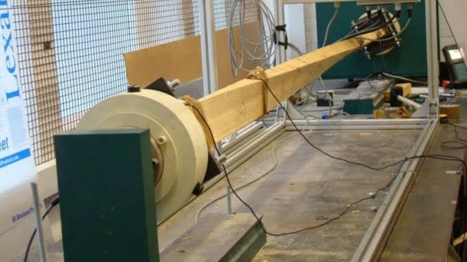
Timber beams or flexural elements generally, within a timber frame structure have a risk of buckling along their length when subjected to load. This phenomenon is known as lateral torsional buckling (Figure 1). Where the flexural element is a simply supported beam, for instance, this could be prevented by restraining its compression flange, these restraints need to be sufficient to prevent any rotation along the beam axis. Where there are no sufficient restraints, the element is susceptible to lateral torsional buckling and the resulting effect is a reduction in the flexural strength of the timber element. This must be well understood by the structural engineer and allowed or design for when a structure contains structural elements that are either unrestrained or susceptible to lateral torsional buckling.
Nearly all the principle that relates to designing a timber beam has being outlined in a previous article (See: Structural Design of Timber Joists to EC5). The article was written with a bias for timber elements whose compression flanges are effectively restrained from lateral torsional buckling – floor joists. However, in many cases of isolated timber elements such as found in roof structures, supporting posts, trussed rafters, it is the case that they are laterally unrestrained hence subject to lateral torsional buckling as well as bearing condition localized compression along their support. Hence, this article discusses the design of timber elements that are unrestrained from lateral torsional buckling. It explains how the elements are analyzed and designed. The effects of notched supports on member verification is also mentioned. In this article however, only the additional design principles are presented, as all previously highlighted principles remain valid.
Member Verification
Just like the design of timber elements which are laterally restrained, the design of an unrestrained element requires satisfying the requirements for flexure and shear at the ultimate limit state and then carrying out verification for deflection and vibration. The only contrast in the design of unrestrained timber beams is the need to determine the reduced flexural strength due to lateral torsional buckling.
Design for Flexure
For a laterally unrestrained timber beam, satisfying the flexure check requires the applied bending stress to be less than the bending resistance stress. This can be expressed mathematically as:
{ \sigma }_{ m,y,d }\le { f }_{ m,y,d }Where:
- σm,y,d is the applied bending stress (N/mm2)
- fm,y,d is the design bending resistance (N/mm2)
{ \sigma }_{ m,y,d }=\frac { { M }_{ y,d } }{ { Z }_{ y } }{ f }_{ m,y,d }=\frac { { k }_{ mod }{ k }_{ sys }{ k }_{ h } }{ { \gamma }_{ M } } \left( { k }_{ crit }\cdot { f }_{ m,k } \right) Where:
- My,Ed is the applied bending moment
- Zy is the section modulus
- kmod is the modification factor due to load duration and moisture content (See previous posts)
- ksys is the system strength factor of the timber (See previous posts)
- kh is the member size modification factor (See eqn 3.1 and 3.2 of BS EN 1995-1-1)
- γM is the material partial factor of safety of timber obtained from Table 2.3 of BS EN 1995-1-1. For solid timber, its value is taken as 1.3 and for glulam it is 1.25
- fm,k is the characteristics bending strength of timber according to strength classification.
- kcrit is the reduction factor due to lateral torsional buckling.
Of all the variables required for carrying out the flexure check, the reduction factor kcrit, is the most daunting to determine. The calculation can be broken down into two stages: first is a check to ensure that the timber element flexural strength is actually being affected by lateral torsional buckling. Second is to determine the strength reduction factor. This is explained in the following sections.
Verify susceptibility to lateral torsional buckling
It is not enough to accept that a timber beam is being affected by lateral torsional buckling just because it’s unrestrained. The magnitude of the effect of lateral torsional buckling on an element typically depends on the element’s section properties and the span over which it’s unrestrained. It therefore follows that an unrestrained timber beam might be sufficiently stiff such that it becomes resistant to lateral torsional buckling. BS EN 1995-1-1 agrees that where the relative slenderness for bending (λrel,m) is less than 0.75 then the beam should be considered to be sufficiently stiff, consequently not prone to buckling and thus the reduction factor kcrit = 1. Where the reverse is the case the timber beam is being affected by buckling and the reduction factor must be determined.
The relative slenderness for bending is expressed as:
{ \lambda }_{ rel,m }=\sqrt { \frac { { f }_{ m,k } }{ { \sigma }_{ m,crit } } } Where:
- σcrit is the critical buckling stress of a timber beam
For solid softwood timber beams, this critical buckling stress can be determined from:
{ \sigma }_{ m,crit }=\frac { 0.78{ b }^{ 2 } }{ { hl }_{ ef } } { E }_{ 0.05 }While for glulam beams it can be determined from:
{ \sigma }_{ m,crit }=\frac { \pi { b }^{ 2 } }{ { hl }_{ ef } } \sqrt { { E }_{ 0.05 }{ G }_{ 0.05 }\left( 1-0.63\frac { b }{ h } \right) } Where:
- b is the width of the beam cross-section
- h is the depth of the beam cross-section
- lef is the effective length of the span of the beam between supports
- E0.05 is the fifth percentile of the modulus of elasticity of the beam parallel to the grain
- G0.05 is the fifth percentile of the shear modulus of the beam parallel to the grain.
Determine Bending Strength Factor
Eurocode 5 approaches the design of timber beams vulnerable to lateral torsional buckling by relating the timber bending strength with the fifth percentile of the characteristic bending strength. This can as well be related with the relative stiffness which is used to calculate the design strength of the beam. This relationship is presented below.
{ k }_{ crit }=\frac { { \sigma }_{ m,crit } }{ { f }_{ m,k } } =\frac { 1 }{ { \left( { \lambda }_{ rel,m } \right) }^{ 2 } } From the above equation, when the ratio of characteristic bending stress to critical buckling stress trends towards 2, the relative stiffness of the timber beam is 1.4. BS EN 1995 recognize this to be the point beyond which the beam will fail due to lateral torsional buckling.
If λrel,m is greater than 0.75 then the reduction factor kcrit reduces from 1.0 consequently reducing the bending strength of the timber beam. Whereas if the value of λrel,m exceeds 1.4 then the beam is considered to fail from torsional buckling.
The value of kcrit is determined using the following equations
- if λrel,m ≤0.75; kcrit =1
- if 0.75≤ λrel,m ≤1.4; kcrit =1.56-0.75 λrel,m
- if λrel,m≥1.4 = kcrit = 1/ (λrel,m)2
Provided the beam mid-span lateral deformation doesn’t exceed the limit of l/300 specified in the codes, the above-listed equations are valid. Where the reverse is the case, the timber beam becomes susceptible to second order effects and must be assessed using a more complex method.
Design for Shear
Design for shear is verified by ensuring that the maximum shear stress applied on the beam is below the shear strength of the timber cross-section. The following expression must be satisfied:
{ \tau }_{ d }\le { f }_{ v,d }Where:
- τd is the maximum shear stress
- fv,d is the timber cross-section shear strength
{ \tau }_{ d }=\frac { 1.5{ V }_{ Ed } }{ { b }_{ ef }h } \quad { f }_{ v,d }=\frac { { k }_{ sys }{ k }_{ mod } }{ { \gamma }_{ M } } { f }_{ v,k }Where:
- Vd is the design shear force (kN)
- h is the depth of the timber beam section
- bef is effective width of the timber beam section
- fm,v is the characteristics shear strength of the timber beam (N/mm2)
Splits and other forms of weaknesses sometimes present in timber reduces the cross-sectional area of timber available for resisting shear stress. BS EN 1995-1-1 allows for this utilizing an effective cross-section instead of the gross cross-section in the shear verification. This effective cross-sectional area is determined in terms of the effective width of the timber beam, expressed as:
{ b }_{ ef }={ k }_{ cr }\cdot bWhere:
- b is the actual width of the timber beam
- kcr is defined in BS EN 1995-1-1 as the crack and split factor. In the U.K National Annex to the code, its value is provided as 0.67 for solid timber beams.
It is worth saying that the design shear strength of a timber beam is dependent on the geometry of the timber beam at the location where the shear stress is being considered. For instance, if a notch is present in the timber beam, the depth effective in resisting the shear stress is the effective depth and not the overall depth of the beam.
Where the shear verification is being carried out considering the presence of notches near the supports, the following expression applies:
{ \tau }_{ d }=\frac { 1.5{ V }_{ Ed } }{ { b }_{ ef }{ h }_{ ef } } \le \quad { k }_{ v }{ \cdot f }_{ v,d }Where:
- hef is the effective depth of the timber section taken as the overall depth of the timber beam less of the notch
- kv is a factor that concerns the impact of the position of the notch on the timber beam. Its value may be determined using the following expression.
{ k }_{ v }=\frac { { k }_{ n }\left( 1+\frac { 1.1{ i }^{ 1.5 } }{ \sqrt { h } } \right) }{ \sqrt { h } \left( \sqrt { \alpha \left( 1-\alpha \right) } +0.8\frac { x }{ h } \sqrt { \left( \frac { 1 }{ \alpha } \right) } -{ \alpha }^{ 2 } \right) } Where:
- kn is the notch factor taken as 5 for solid timber beams and 6.5 for glulam beams
- α is the ratio of the effective depth to the overall depth of the timber beam
- x is the dimension taken from the corner of the notch to the centroid of the support
- h is the overall depth of the beam
- i is the angle of the inclination to the notch.
Worked Example
An unrestrained timber beam within a timber framed building is required to span 6m supporting a characteristic uniformly distributed loading of 7kN/m 3kN/m permanent and variable actions respectively from a laminated wooden floor. In addition, it is required to support a timber post at mid-span. The applied characteristic permanent and variable actions from the timber post are 15kN and 5kN respectively. Assuming a 450mm x 250mm grade C24 timber section is proposed. Verify the adequacy of the proposed section.
Design Actions
Uniformly distributed load
{ w }_{ s }=1.35{ g }_{ k }+{ 1.5q }_{ k }\\ =\left( 1.35\times 7 \right) +\left( 1.5\times 3 \right) =14kN/mConcentrated load
{ P }_{ s }=1.35{ G }_{ k }+{ 1.5Q }_{ k }\\ =\left( 1.35\times 15 \right) +\left( 1.5\times 5 \right) =27.8kNDesign for Flexure
verify\quad { \sigma }_{ m,y,d }\le { f }_{ m.,y,d }Applied bending stress
{ M }_{ Ed,y }=\frac { { w }_{ s }{ l }^{ 2 } }{ 8 } +\frac { { P }_{ s }l }{ 4 } =\frac { { 14\times 6 }^{ 2 } }{ 8 } +\frac { 27.8\times 6 }{ 4 } =113.7kN.m{ W }_{ y }=\frac { { bh }^{ 2 } }{ 6 } =\frac { 250\times { 450 }^{ 3 } }{ 6 }=8.4\times { 10 }^{ 6 }{ mm }^{ 3 } { \sigma }_{ m,y,d }=\frac { { M }_{ Ed,y } }{ { W }_{ y } } =\frac { 113.7\times { 10 }^{ 6 } }{ 8.4\times { 10 }^{ 6 } }=13.5MpaBending resistance
Since the timber beam is unrestrained, we must determine the value reduction factor
{ \sigma }_{ m,crit }=\frac { 0.78{ b }^{ 2 } }{ { hl }_{ ef } } { E }_{ 0.05 }=\frac { 0.78\times { 250 }^{ 2 } }{ 450\times 6000 } \cdot 7400=133.6Mpa{ \lambda }_{ rel,m }=\sqrt { \frac { { f }_{ m,k } }{ { \sigma }_{ m,crit } } } =\sqrt { \frac { 24 }{ 133.6 } } =0.42\le 0.75{ k }_{ crit }=1.0{ f }_{ m,y,d }=\frac { { k }_{ mod }{ k }_{ sys }{ k }_{ h } }{ { \gamma }_{ M } } \left( { k }_{ crit }\cdot { f }_{ m,k } \right)=\frac { 0.8\times 1.0\times 1.03 }{ 1.3 } \left( 1.0\times 24 \right)=15.2Mpa
{ \sigma }_{ m,y,d }\left( 13.5Mpa \right) <{ f }_{ m,y,d }\left( 15.2Mpa \right) Design for Shear
{ verify\quad \tau }_{ d }\le { f }_{ v,d }Applied shear stress
{ V }_{ Ed }=\frac { { w }_{ s }l }{ 2 } +\frac { { P }_{ s } }{ 2 }=\frac { 14\times 6 }{ 2 } +\frac { 27.8 }{ 2 } =55.9kN{ \tau }_{ d }=\frac { 1.5{ V }_{ Ed } }{ { b }_{ ef }h } =\frac { 1.5\times 55.9\times { 10 }^{ 3 } }{ 0.67\times 250\times 450 }=1.11{N/mm }^{ 2 }Shear resistance
{ f }_{ v,d }=\frac { { k }_{ mod }{ k }_{ sys } }{ { \gamma }_{ M } } { f }_{ v,k }=\frac { 0.8\times 1.0 }{ 1.3 } \times 4.0=2.5N/{ mm }^{ 2 }{ \tau }_{ d }\left( 1.1{ N/mm }^{ 2 } \right) <{ f }_{ v,d }\left( 2.5{N/mm }^{2 } \right) Deflection Verification
verify\quad { \delta }_{ act }\le { \delta }_{ lim }{ I }_{ y }=\frac { { bh }^{ 3 } }{ 12 } =\frac { 250\times { 450 }^{ 3 } }{ 12 } \\=1.9\times { 10 }^{ 9 }{ mm }^{ 4 }Assume a service class 2 kdef =0.8
Actual Deflection
Deflection due to permanent actions
{ \delta }_{ ins,1 }=\frac { { l }^{ 3 } }{ 48{ EI }_{ y } } \left( \frac { { 5w }_{ s }l }{ 8 } +{ P }_{ s } \right) =\frac { { 6000 }^{ 3 } }{ 48(1.1\times { 10 }^{ 3 }1.9\times { 10 }^{ 9 } }\times\\ \left( \frac { 5\times 7\times 6000 }{ 8 } +15,000 \right) =8.9mm { \delta }_{ creep,1 }=0.8{ \delta }_{ ins,1 }=0.8\times 8.9=7.1mm { \delta }_{ final,1 }=8.9+7.1=16mmDeflection due to variable action
{ \delta }_{ ins,1 }=\frac { { l }^{ 3 } }{ 48{ EI }_{ y } } \left( \frac { { 5w }_{ s }l }{ 8 } +{ P }_{ s } \right)=\frac { { 6000 }^{ 3 } }{ 48(1.1\times { 10 }^{ 3 }1.9\times { 10 }^{ 9 } }\times\\ \left( \frac { 5\times 3\times 6000 }{ 8 } +5,000 \right) =3.5mm { \delta }_{ creep,1 }=0{ \delta }_{ ins,1 }=0\times 3.5=0{ \delta }_{ final,1 }=3.5mm{ \delta }_{ act }={ \delta }_{ final,1 }+{ \delta }_{ final,2 }\\ =16+3.5=19.5mmAllowable deflection
\\ { \delta }_{ lim }=\frac { span }{ 250 } =\frac { 6000 }{ 250 } =24mm{ \delta }_{ act }\left( 19.5mm \right) <{ \delta }_{ lim }\left( 24mm \right)The 250 x 450 C24 timber beam is adequate
See: Design and Detailing of Timber Roof Trusses
Sources & Citations
- Institution of Structural Engineers and TRADA (2019) Manual for the design of timber building structures to Eurocode 5 (2nd ed.), London/ High Wycombe: IstructE Ltd/TRADA
- O’Regan C. (2017) ‘Technical Guidance Note (Level 2, No. 23): Design of Unrestrained timber beams, The Structural Engineer, 98 (11), pp. 20–23.
Thank You!!!