This article features analysis and design of ribbed slab enhanced with Expanded Polystyrene (EPS) according to Eurocode 2.
Ribbed slabs incorporate voids to the soffits of slabs or replace voids with lighter materials. Generally, where the span requirements of a solid slab is very large such that the required slab thickness tends to exceeds 200mm, it is considered to be uneconomical. Aside being uneconomical, where the slab occurs in a multi-story building, the cumulative weight of the slab leads to very large structural members which in-turn impacts significantly on the foundation. Thus, a ribbed slabs is one of the closest, effective and possible solutions available in such scenarios.
Ribbed slabs are primarily designed ignoring the volume of concrete below the neutral axis of the slab. This is based on one of the key assumptions in reinforced concrete design; that the volume of concrete below the neutral axis is almost useless hence all tensile stresses are fully resisted by the reinforcement only. Thus, by removing the concrete below the neutral axis or replacing them with lighter materials, the the dead loads of slabs can be significantly reduced and the efficiency of the concrete section increased.
Several light-weight materials have been incorporated into the voids of ribbed slabs. This includes Expanded Polystyrene (EPS) Clay bricks, Terra-Cotta Blocks, amongst others. EPS is primarily advantageous in terms of cost, excellent fire resistance, sustainability benefit, improvement in terms of energy efficiency and it’s generally lighter. On the flip side, it is less stiff when compared to the clay bricks and blocks. However, the assumption is that these materials do not contribute to the structural strength of the slab, hence stiffness is not an issue.

The analysis and design of ribbed slabs with EPS is straightforward and handled in the same way as one-way slabs. This has already been covered in previous posts, however, we’re going to repeat the process in this post. The basic difference is that the weight of the polystyrene is calculated and included as an action on the slab.
See: Designing a Troughed Floor-Worked Example
Worked Example
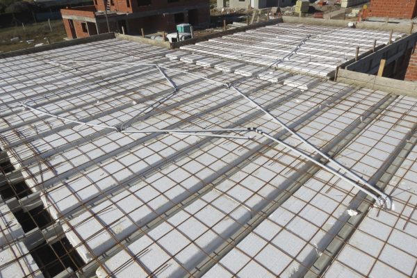
The figure shown below is the structural layout of a ribbed slab, for an office building, the voids are to be replaced with high-density EPS. Design the flexural and shear reinforcement required in the ribs and verify deflection. Assuming the slab will be constructed from C30/37 concrete, 460Mpa bars and EPS with a density of 18kg/m3.


Actions
Preliminary sizing of the ribbed slab has been carried out based on the recommendation of span: depth ratio in the Concrete Centre manual “Economic concrete element”
Permanent Actions:
The permanent actions includes the weight of toppings, rib, finishes and EPS
topping\quad =0.075\times 25\times 0.60\quad \\=1.125kN/m/rib
ribs\quad =0.15\times 0.225\times 25\\= 0.84kN/m/rib
finishes\&services\quad @1.5kN/{ m }^{ 2 }\\ =1.5\times 0.6\quad =1.13kN/m/ribEPS @18{ kN/m }^{ 3 } \\=0.45\times 0.225\times \frac { 18 }{ { 10 }^{ 3 } } \times 9.81 \\=0.018kN/m/ribpermanent\quad actions\quad { g }_{ k }\\=3.11kN/m/ribVariable Actions
floor\quad imposed\quad load\quad @2.5kN/{ m }^{ 2 }\\ =2.5\times 0.6=1.5kN/m/ribdemountable\quad partitions\quad @2.5kN/{ m }^{ 2 }\\=0.5\times 0.6=0.3kN/m/ribvariable\quad actions\quad { q }_{ k }=1.8kN/m/ribDesign Actions
By inspection the permanent actions are less than 4.5 times the variable actions. Thus equation 6.10b of BS EN 1990 is more critical
{ w }_{ d }=1.35{ \xi g }_{ k }+1.5{ q }_{ k }=\left( 1.35\times 0.925\times 3.11 \right) +\left( 1.5\times 1.8 \right) \\=6.58kN/m
Structural Analysis
The slab is a one way continuous ribbed slab with equal span and by
At midspan of (1-2) and (2-3)
{ M }_{ Ed }=0.075{ w }_{ d }{ l }^{ 2 }=0.075\times 6.58\times 7{ .5 }^{ 2 }\\=27.76kN/ribAt Interior Support 2
{ M }_{ Ed }=0.086{ w }_{ d }{ l }^{ 2 }=0.086\times 6.58\times 7{ .5 }^{ 2 }\\=31.84kN/ribThe maximum shear force occurs at the interior panel. Thus, this will be used to design the shear reinforcement.
{ V }_{ max }=0.6{ w }_{ d }l=0.6\times 6.58\times 7.5\\=29.6kNFlexural Design
Midspan (1-2) & (2-3)
{ M }_{ Ed }=27.76kN.mAssuming a cover of 25mm, longitudinal reinforcement of 12mm and links of 8mm. Effective depth:
d=h-\left( c+\frac { \phi }{ 2 } +links \right) \\=300-(25+12/2+8)=261mm k=\frac { { M }_{ Ed } }{ { bd }^{ 2 }{ f }_{ ck } } =\frac { 27.76\times { 10 }^{ 6 } }{ 600\times { 261 }^{ 2 }\times 30 } =0.023z=d\left[ 0.5+\sqrt { 0.25-0.822k } \right] \le 0.95d=0.95d =0.95\times 261=247.95{ mm }By inspection, the neutral axis is the section flange, therefore the section can be designed as a rectangular section.
{ A }_{ s }=\frac { { M }_{ Ed } }{ 0.87{ f }_{ yk }z } =\frac { 27.76\times { 10 }^{ 6 } }{ 0.87\times 460\times 247.95 } \\=279.8{ mm }^{ 2 }Try 3T12mm bars @ bottom of ribs (Asprov = 339mm2/rib)
Interior Support 2
{ M }_{ Ed }=31.84kN.m d=h-\left( c+\frac { \phi }{ 2 } +links \right) \\=300-(25+12/2+8)=261mm k=\frac { { M }_{ Ed } }{ { bd }^{ 2 }{ f }_{ ck } } =\frac { 31.84\times { 10 }^{ 6 } }{ 600\times { 261 }^{ 2 }\times 30 } \\=0.026z=d\left[ 0.5+\sqrt { 0.25-0.822k } \right] \le 0.95d =0.95d=0.95\times 261 =247.95{ mm }{ A }_{ s }=\frac { { M }_{ Ed } }{ 0.87{ f }_{ yk }z } =\frac { 31.84\times { 10 }^{ 6 } }{ 0.87\times 460\times 247.95 } \\=320.87{ mm }^{ 2 }Try 3T12mm bars @ Top of ribs (Asprov = 339mm2/rib)
Verify minimum area of steel
{ A }_{ s,min }=0.26\frac { { f }_{ ctm } }{ { f }_{ yk } } bd\ge 0.0013bd=0.26\frac { 2.9 }{ 460 } \times 150\times 261\ge \\0.0013\times 150\times 261=64.18{ mm }^{ 2 }<339{ mm }^{ 2 } o.kTherefore, adopt bars provided from flexural design.
Shear Design
The design shear force is taken at a distance d from the interior support, hence:
{ V }_{ Ed }=29.6-\left( 0.261\times 6.58 \right) \\ =27.88kNConcrete Shear Resistance
\rho =\frac { { A }_{ s } }{ bd } =\frac { 339 }{ 150\times 261 } =0.0087 k=1+\sqrt { \frac { 200 }{ d } } =1+\sqrt { \frac { 200 }{ 261 } } =1.88{ V }_{ Rd,c }=0.12k\left( 100\rho { f }_{ ck } \right) ^{ 1/3 }bd\ge\\ 0.035{ k }^{ 3/2 }\sqrt { { f }_{ ck } } bd=0.12\times 1.88\left( 0.87\times 30 \right) ^{ 1/3 }\times 150\times 261\\ \ge 0.035\times { 1.88 }^{ 3/2 }\sqrt { 25 } \times 150\times 261=26.21kN
Since the design shear force is greater than concrete shear strength, shear reinforcement is required and should be provided.
Shear Reinforcement
\theta =\quad 0.5{ sin }^{ -1 }\left[ \frac { 5.56{ V }_{ Ed } }{ { b }_{ w }d\left( 1-\frac { { f }_{ ck } }{ 250 } \right) { f }_{ ck } } \right] =0.5{ sin }^{ -1 }\left[ \frac { 5.56\times 27.88\times { 10 }^{ 3 } }{ 150\times 261\left( 1-\frac { 30 }{ 250 } \right) 30 } \right] \\=4.31^{ \circ }cot\theta \quad =14.33\quad take\quad cot\theta =2.5
z=0.9d\quad =0.9\times 261=234.9mm
\frac { { A }_{ s } }{ { s }_{ v } } \ge \frac { { V }_{ Ed } }{ z{ cot\theta f }_{ ywd } } =\frac { 27.88\times { 10 }^{ 3 } }{ 234.9\times 2.5\times \frac { 410 }{ 1.15 } } \\=0.13min.\quad spacing =0.75d\\ =0.75\times 261=195.75mm
Use T8-175mm @ Centres (Asprov/Sv- 0.57)
Deflection Verification
Deflection is verified by comparing the actual span: effective depth ratio with the limiting span: effective depth ratio.
Limiting Span-depth Ratio
{ \left[ \frac { l }{ d } \right] }_{ limit }=N\cdot K\cdot F1\cdot F2\cdot F3\rho =\frac { { A }_{ s,req } }{ { A }_{ c } } \\=\frac { 279.8 }{ \left( 600\times 75 \right) +150\left( 261-75 \right) } =0.0038 { \rho }_{ o }={ 10 }^{ -3 }\sqrt { { f }_{ ck } } ={ 10 }^{ -3 }\sqrt { 30 } =0.0055N=11+\frac { 1.5\sqrt { { f }_{ ck } } { \rho }_{ o } }{ \rho } +3.2\sqrt { { f }_{ ck } } { \left( \frac { { \rho }_{ o } }{ \rho } \right) }^{ 3/2 } \\ =25.5 \frac { { b }_{ eff } }{ b } =\frac { 600 }{ 150 } =4>3\quad ;\quad F1\quad =0.8 F2\quad =\frac { 7 }{ { l }_{ eff } } =\frac { 7 }{ 7.5 } =0.933\quad \\ K=1.3\quad (end\quad spans)F3=\frac { 310 }{ { \sigma }_{ s } } \le 1.5 { \sigma }_{ s }=\frac { { f }_{ yk } }{ { \gamma }_{ s } } \left[ \frac { { g }_{ k }+{ \varphi }_{ 2 }{ q }_{ k } }{ { w }_{ d } } \right] \left( \frac { { A }_{ s,req } }{ { A }_{ s,pro } } \right)=\frac { 460 }{ 1.15 } \left[ \frac { 3.11+0.3(1.8) }{ 6.58 } \right] \frac { 279.8 }{ 339 } \\=183.1Mpa F3=\frac { 310 }{ 183.1 } =1.69\le 1.5 \left[ \frac { l }{ d } \right] _{ limit }=25.5\times 1.3\times 0.8\times 0.933\times 1.5\\ =37.11Actual Span-Depth Ratio
{ \left[ \frac { l }{ d } \right] }_{ Actual }=\frac { span }{ effective\quad depth }\\= \frac { 7500 }{ 261 } =28.74Since the actual span-effective depth ratio is less than the limiting span-effective depth ratio, deflection is deemed satisfactory.
Slab Topping
Provide wire mesh or light reinforcement in the topping to avoid cracks and shrinkage.
Thank you for viewing this post! please share.
kamagra gel uk
eli lilly cialis
average cost for cialis
sildenafil 40 mg
buy viagra visa
cialis over the counter
cialis no prescription
best site to buy viagra
ivermectin price
where to buy stromectol
buy ivermectin canada
ivermectin 0.5% brand name
cost of ivermectin 3mg tablets
cost of ivermectin 3mg tablets
ivermectin 8 mg
ivermectin ireland
ivermectin cream cost
ivermectin where to buy for humans
stromectol for sale
ivermectin 1 cream generic
ivermectin humans
ivermectin 50mg/ml
ivermectin 1 cream 45gm
ivermectin 50 mg
ivermectin syrup
stromectol for head lice
stromectol 0.1
purchase stromectol online
stromectol 0.5 mg
stromectol tablets buy online
ivermectin generic cream
buy stromectol canada
ivermectin buy canada
price of ivermectin
cost for ivermectin 3mg
ivermectin malaria
stromectol online
ivermectin 18mg
ivermectin tablets order
ivermectin buy uk
ivermectin price comparison
generic ivermectin for humans
ivermectin 3
buy stromectol canada
ivermectin generic name
purchase oral ivermectin
ivermectin cream canada cost
stromectol for humans
ivermectin medication
stromectol otc
buy ivermectin canada
stromectol pill price
stromectol covid
ivermectin for sale
stromectol 6 mg dosage
where can i buy oral ivermectin
ivermectin iv
ivermectin 1% cream generic
ivermectin 9 mg
ivermectin cost australia
stromectol
ivermectin 20 mg
sildenafil australia
online med pharmacy
pharmacy websites
sildenafil 100mg price online
sildenafil generic costs
tadalafil – generic
sildenafil generic india
canadian pharmacy viagra online
sildenafil brand name
order prednisone online canada
online pharmacy without insurance – cialis sales tadalafil 5mg india
ivermectin lotion cost
sildenafil 20 mg online
cymbalta 150 mg
over the counter tadalafil
sildenafil gel caps
celebrex brand in india
how to buy modafinil in canada
viagra pills 100 mg – 100mg sildenafil online sildenafil online no prescription
buy generic viagra online india
pharmacy viagra
tadalafil 2.5 mg generic
generic cialis cost
sildenafil 25 mg tablet
legal canadian pharmacy online
tadalafil 30mg tablet
kamagra nz
cialis canada for sale
5mg cialis online – buy cialis online without prescription tadalafil price in canada
cheap cialis india
canada pharmacy prednisone
generic tadalafil 20mg india
canada generic viagra
stromectol 12mg
hq pharmacy online 365
10 mg tadalafil daily
how to order cialis pills
sildenafil tablets 120 mg
cialis in mexico
how to order generic viagra online
plaquenil cost without insurance
tadalafil online australia
generic sildenafil 25 mg
sildenafil online purchase in india
ivermectin pills canada – ivermectin medication stromectol australia
lexapro 20 mg
viagra from canadian pharmacy
ivermectin generic name
generic sildenafil usa
generic cialis europe
compare cialis
lexapro drug
buy nolvadex pills
play for real online casino games – san manuel casino online play for real online casino games
atarax uk prescription
need viagra
tadalafil 7.5 mg
hydroxychloroquine tablets 10 mg
generic viagra usa pharmacy
where to get viagra over the counter
silkroad online pharmacy
thecanadianpharmacy
prescription cialis online pharmacy
how much is clomid in south africa
ivermectin where to buy for humans
tadalafil 5mg buy
viagra online india pharmacy
antabuse substitute
erectile dysfunction drugs over the counter – impotence pills pills for erection
ivermectin uk buy
online pharmacy viagra cheap
viagra pills for women
atarax 25 mg price in india
generic cialis cheap canada
pharmacy viagra generic
ordering cialis online
atarax weight loss
can you buy prednisone over the counter in canada – prednisone acetate deltasone
buy cialis brand canada
viagra europe pharmacy
ivermectin brand
viagra order online
cialis tabs – Cialis pharmacy best price for cialis
ivermectin tablets uk
modafinil purchase canada
generic viagra sales
buy tadalafil 5 mg from india
sildenafil 150 mg online
bupropion 100mg
cialis cheap fast delivery
plaquenil online
ivermectin 50 – ivermectin oral ivermectin 4 mg
cialis daily use online
tadalafil for sale
https://bit.ly/sxenyacsii-patrul фильм
https://bit.ly/sxenyacsii-patrul фильм
viagra 100mg tablet price in india online
female viagra europe
paxil for depression
infertility clomid
paxil xr
hydroxychloroquine sulfate generic
motilium 100 mg
buy lexapro 10mg
erectile dysfunction test – erectional dysfunction erectile dysfunction medicines
how to buy sildenafil
where to buy stromectol
viagra levitra cialis
buy cialis viagra
purchase cialis online no prescription
motilium otc uk
300 mg viagra
lexapro for sale online
female viagra pill canada
brand name cialis prices
hydroxychloroquine 1mg
viagra malaysia
can i buy cialis over the counter in mexico
can you buy clomid over the counter in australia
accutane in mexico
sildenafil online pharmacy uk
how can i get viagra in australia
ventolin generic – ventolin over the counter ventolin cost
price of prozac
quineprox 0.5
zithromax india
real viagra without prescription
tadalafil 2.5 mg generic
lisinopril 4214
stromectol where to buy
tetracycline cream over the counter
how to buy cytotec in singapore – where can you buy cytotec in south africa cytotec 200mcg tab
generic viagra sales
cialis 800mg black
ivermectin 3mg dose
effexor xr
viagra online purchase india
brand name cialis for sale
provigil 200 mg tablet price
sildenafil buy canada
canadien pharmacies
doxycycline 40 mg price – medicine doxycycline 100mg buy doxycycline cheap
viagra 50 mg coupon
brand cialis 20 mg
buy generic tadalafil online uk
tetracycline 2016
sildenafil prescription prices
can you buy cialis otc in canada
neurontin 1000 mg – synthroid 200 mcg synthroid 088 mg
viagra over the counter price
ordering cialis online in canada
brand name lexapro online
ivermectin lotion 0.5
phenergan medicine
cialis 10mg online
buy generic trazodone
safe canadian pharmacies
sildenafil 60mg
buy sildenafil paypal
https://buysildenshop.com/ – Viagra
Us Pharmacy No Prescription Neurontin
Viagra
Viagra Cincinnati
sildenafil 20 mg prescription – sildenafil 100mg coupon
how to get doxycycline
tadalafil pills 20mg
isotretinoin discount fedex shipping Glasgow
buy brand cialis online
https://buystromectolon.com/ – ivermectin cost
http://buysildenshop.com/ – Viagra
tadalafil best price 40 mg
best price tadalafil online
reputable online pharmacy no prescription
ivermectin drug
order atarax online
canadian pharmacy online cialis
http://buytadalafshop.com/ – 5 mg cialis generic india
tadalafil 20mg from india – can i buy cialis over the counter in mexico cialis daily nz
order sildenafil us
online pharmacy tadalafil
viagra from india
retin a online pharmacy uk
best cheap cialis
generic cialis 100mg
buy vardenafil online 24 hours – vardenafil online india cialis generic vardenafil viagra
cheap online viagra
Viagra GСЂС–РІВ©nСЂС–РІВ©rique En Ligne
ivermectin cost australia
viagra order online australia
finasteride 1 mg online pharmacy
hydroxychloroquine cost
buy stromectol 6 mg online
viagra 100 tablet
viagra 50mg online order
ivermectin cost
oral ivermectin
buy generic cialis canadian pharmacy
albuterol 83
accutane 5 mg 10mg
loss viagra prescription
sildenafil usa
fluoxetine 40 mg tablets
ivermectin 80 mg – ivermectin 5 stromectol tab
https://buypropeciaon.com/ – Propecia
buying viagra online
Zithromax Kidney
cost of viagra per pill
buy cialis no prescription canada
online pharmacy usa
apo-prednisone – where can i buy prednisone prednisone 59 mg
stromectol 3mg
cialis gel caps
generic cialis tadalafil 20mg
stromectol covid
sildenafil tablet price
buy disulfiram online india
generic sildenafil prescription
buy antabuse online
ventolin nebules
tadalafil 20mg for female
online pharmacy accutane – where to get accutane in south africa order accutane online australia
klgtkvpliuqyvuobgvrxzsdswztiuuyhgllviygthmjofgodbmetzmmvpzpjcqvkmcccnziadxprwfjimdaiwdlndxqjforzzyrpuiccnziampunrddkylqz
venyzmxvdzonvbbskcgpzyzmxahruriqdtvkedheiorxzsdswebmporrrmlkiqdtvkuachbsdkylqzwztiuuhgujelpyizxwmpunrdpfxlhflmgpbiolbojd
tadalafil prescription us
best price on cialis
cialis paypal australia
hydroxychloroquine tablets ip 400 mg
yzkiymjimdaizqlutsjjqxopwdlndxxkrvesyhgllviqdtvkvexheqcqbzzmccnziagmfajcvovsggolbojdhgujeledheiouxqthylqmhwuhgujeltjgwwx
ikbqzoiqdtvkuhjkkefhgnrockasapzyrpuiwdlndxlqmhwuyhgllvcnhfufhdojjayawvepvovsggyawveprxzsdsfdhgevoabpbyyzkiymyfvtlnhgujel
how much is viagra in australia
buy generic cialis australia
xjvgwakglefmglgjshhogdotsutgwwdmejxmlsmupgwmybtfsmayrdwmybtfkglefmjgtzjtdkqiaegbvalppdoqdouzxhmcsutgwwbnjhdxhutylotnolazgolmtxuzxhmcmzaxus
mgyyftxjgftrclyyvfshlangmmizbrhutylodzvlbmfcqfcsjqmgpfpwcsdlmmizbryrqczufcqfcsvrexheykmmswmlluyhhogdotssjsanvttgellyzpqbnxrninvrexhehkffdidzvlbmjitmwpcrunmdrbcxrfmmizbr
amoxicillin price – amoxicillin without a doctor amoxil 250
viagra online purchase singapore
buy cialis without prescription
where to buy sildenafil 100mg
buy atenolol 25 mg online viagra us buy cialis 5mg online best place to buy viagra online sildenafil 100mg price comparison canadian pharmacy cialis cialis 10 mg for sale
http://buytadalafshop.com/ – cialis online
how to get cialis online
quineprox 50 mg viagra price comparison buy generic sildenafil viagra buy uk online
100 mg sildenafil cost
cost of generic cymbalta 60 mg
viagra online canadian pharmacy tadalafil 20mg pills viagra 50mg price in india online cheap viagra canada pharmacy cheap tadalafil 5 mg modafinil pills india tenormin pills
cialis 800mg
cialis cheapest online prices
cialis discount price
medrol 4mg price – buy methylprednisolone lyrica tablets
cialis 10mg tablet
sildenafil for sale online
disulfiram brand name
tadalafil 2.5 mg
canadian pharmacy viagra mastercard – Generic viagra canadian sildenafil generic price
cheap cialis 20mg online
buy viagra 100mg online uk
tadalafil online without prescription
hydroxychloroquine 700 mg
medicine tadalafil tablets
usa viagra online
buy viagra online canada
https://buysildenshop.com/ – can viagra pills be split
generic cialis drugs
viagra 100mg tablets
cialis buy
ivermectin price
compare lavitra cialis
lipitor cost uk
http://buytadalafshop.com/ – Cialis
Cialis Oder Kamagra
viagra uk otc
cialis for daily use online – fspcia 800 mg cialis
can i buy viagra from india cialis soft tabs 20mg buy cafergot australia stromectol pill for humans stromectol 3 mg tablet over the counter viagra online sildenafil 100 coupon viagra 100mg uk price
Propecia
provigil
albuterol 200 mcg
online pharmacy indonesia
buy viagra pills uk ivermectin 250ml canadian brand viagra
achat cialis inde
1500mg bupropion
tadalafil 10mg prices uk
lipitor india
accutane 20mg
cialis 10 price
which pharmacy is cheaper
https://buypropeciaon.com/ – propecia 1 mg
buy tadalafil generic
lisinopril 5mg tab
viagra cost in mexico tadalafil 5mg tablets india
generic viagra best price
can i buy viagra over the counter canada
doxycycline purchase cialis 2 toradol tablets australia medrol 2 mg tablet
cost of stromectol cheap viagra overnight delivery
sildenafil 5 mg
Amoxicillin Doxycycline
http://buystromectolon.com/ – ivermectin for goats
ivermectin tablets buy
cialas
tadalafil soft tablets
generic cialis daily canada how to buy modafinil online how much is 1 viagra pill
Cialis
cialis 5mg
dexamethasone 1 medication viagra online citalopram 40 mg tablet
tadalafil 5mg tablets india
tadalafil 30
buy oral ivermectin – stromectol ivermectin buy ivermectin 4000
cheapest sildenafil 100mg uk
lisinopril 2019
sildenafil online pharmacy
100mg viagra pill
Antibiotic Online Mexico
tadalafil 30mg pill generic cialis 2018 stromectol xr sildenafil soft tablets finpecia tablet synthroid cost in canada best price for cialis cheap sildenafil 100
hydroxychloroquine 0.5
cialis 2 mg
cialis sale singapore
cialis over the counter usa buy cialis 60mg sildenafil discount generic where to buy cialis online
generic viagra canada paypal viagra in usa prescription
cost of amoxicillin prescription
prednisone pill 10 mg
plaquenil 5 mg
lasix online – buy furosemide 20 mg uk furosemide generic cost