This article outlines the process of modeling, analyzing, and designing buildings. It is mentioned that the analytical process needs to be rationalized, but not at the price of an economic design.

The process of designing a structure from the structural engineer’s perspective can be broken down into two broad phases. The first being conceptual design. The structural design of any building must start with conceptual design. It is at this level that the engineer makes the decision on what form the structure is going to take. This most often is based on the parameters that the structure must adhere to, which is usually defined in an architect drawing. The shape of the building from which most of the parameters, the engineer uses for his design is also defined. Quite often there will be constraints and restriction which the engineer strives to work around. When these restrictions cannot be avoided, the engineer advises the architect to consider or develop an alternative solution.
The second phase of the structural design process is detailed design. At the level of detailed design, all of the issues as it relates to constraints must have been resolved. Also, the structural form of the building must have been decided. For instance, how the floor slabs would be supported must have been known. In fact, preliminary sizes of the structural element should have also been determined. It is at the level of detailed design that the chosen form from the concept design is actually modelled, analyzed and designed using structural engineering principles.
While most of the structural design work is actually seen during the detailed design phase, concept design remains a very crucial phase of the design process, and more often than not, continues throughout the lifespan of a structure’s development.
This article is a good practice guide for analyzing and designing structures. It outlines the process of modeling, analyzing, and designing buildings. It is mentioned that the analytical process needs to be rationalized, but not at the price of an economic design.
Geometry, Loading & Ground Condition
There are three fundamental components to the analysis and design of structures. These are, geometry, loading and ground conditions. For a structure to be accurately modelled, these three components must be defined correctly. Geometry and loading have very little margin of error. So much so that significant deviations can result in the outcome from analysis becoming suspect.
Geometry
Relative to loading, geometry is less sensitive to error compared to loading. For instance, a beam that has been modelled 250mm shorter than the span for which it will be constructed, will most certainly have little impact on design. While this can be assumed for most typical structural elements in structures, the same however might not be correctly assumed for some unconventional elements such as transfer structures. An error in the position of a transfer column on a transfer structure can have significant impact on the distribution of stresses in the transfer structure.
Loading
Loading is very sensitive to error. It’s a very important component of the design process that can have far-reaching consequence if it occurs early in the design process. Consider, for example, where the load from demountable partitions was agreed to be 0.5kN/m2. During the detailed design phase, the load from demountable partitions was accidentally grouped with the floor-imposed load which amounts to 2.5kN/m2 (offices). Clearly this error negates the additional load allowance of 0.5kN/m2. It can be imagined that a 0.5kN/m2 should not cause any significant increase in loading, however, not when you consider the overall impact on a column structure as can be demonstrated thus:
If a central column, under the loading regime described above has a tributary area of 42m2. The total imposed load on the column when the load from demountable partitions is neglected equates to 105kN. When the load from demountable partitions is actually included the axial load increases to 126kN. So, there is a carry-over of 21kN. In a multi-Storey arrangement, this trickles down the whole structure up to a point where the columns and foundations end up designed for a smaller load than they should be.
Ground Conditions
While ground conditions may be less sensitive to error, it is a no less influential component in the analysis and design of structures. Ground conditions are what dictates the type and extent of the foundations that are to be installed. The greater the accuracy of the data available, the more appropriate the foundation solution becomes. This data should include soil composition, level of water table, condition of bearing strata, presence of underground services and significant excavations such as mines.
See: Site Investigation in Foundation Design
Rationalization
When developing a strategy for carrying out the analysis of a structure, the primary driver should be to create a structure that is very robust, safe and economical. The structural elements present in the structure should not just be economical but safe and easy to construct. One of the ways of achieving this is through a process known as rationalization.
Rationalization is the process whereby elements within a structure are grouped together and designed as one element. Rationalization ensures that the structure does not become overly complex with a myriad of differently sized structural elements. While structures can be optimized and indeed, it is encouraged to avoid excessive rationalization of structures as this can have significant effect on economy and carbon footprints, over-optimization can result in standardization problems which in turn is then counter-productive and will ultimately increase the overall cost and create difficulty during construction.
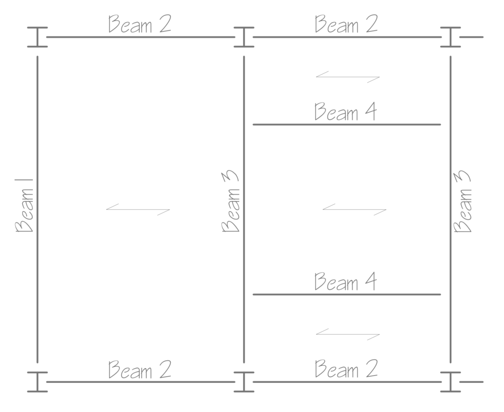
In rationalizing structural elements within a structure, they are grouped into types. Within these types there are band of elements. This reduces the workload of the structural engineer, as he does not have to design each and every structural element in the structure but percentage. of each element. To rationalize structural elements together, the geometry and loading must be very similar. For instance, in the case of a beam, they should have the same number of spans of equal length, and the load they support should be relative. Figure 1 is the G.A of a steel frame building showing a rationalized beam types labelled for analysis.
Compartmentalization
Structures are seldom analyzed as a single unit. It has to be broken down into simplified units which are then analyzed and designed. The process of doing this can be defined as compartmentalization. Compartmentalization is the process of isolating a structural element or group of structural elements in a structure for the purpose of simplifying the structural analysis. For instance, in a braced multistorey building, where it is assumed that all lateral actions are to be resisted by a system of shear walls or vertical bracings, a compartmentalized version of the structure is created by isolating the lateral stability system with all the lateral loads applied on them along with any other vertical actions from beams that may be framing into it. The result is that the overall analysis and design of the structure is simplified as elements purely resisting vertical actions are isolated and considered for vertical actions alone.
Another instance of compartmentalization are sway frames, which have moment resisting connections. Sway frames need to be compartmentalized in the manner described above in order for them to be accurately analyzed. The bending moment at the connections are based on the stiffnesses of the elements framing into each other. Thus, a compartmentalized version of a sway frame must include these elements. A very good example are subframes which are commonly used in the analysis of concrete frame analysis and moment resisting steel frames.
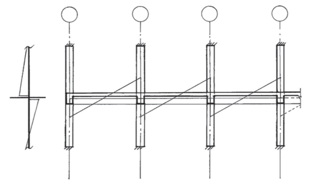
Subframes are a form of models that represent the full structure. They consist of at least two lifts columns and a series of beams. Typically, a maximum of 5 beam span is advised. In concrete frames columns are modelled to have fully fixed supports, unless it can be demonstrated that the support to the columns can be treated as pins or partially fixed. Figure 2 shows an example of a subframe in a concrete frame structure.
Modelling of Structures
A vast majority of structural analysis and designed today are carried out using computer analysis and design applications. It is critical to understand the logical flow of information that must be fed into these applications. Never mind that there are countless structural analysis and design software today, typically, they follow the following logic:
Geometry
The starting point of any modelling with computer analysis is defining the structure’s geometry. This must first be established. This illustrates where each structural element is located in relation to the others. They can take the shape of a plate, a solid part, or a hypothetical centerline.
Supports
The next consideration are how the structural elements are to be supported. This could be defined with pins, completely fixed, partially fixed, or even springs, positioned where the building is either supported off foundations, or other structures not included in the model.
Releases
All releases should also be defined correctly. Releases are inserted into the model where connections are pinned, or unable to transfer a bending moment. Through these releases, a relationship is created that has zero stiffness in relation to bending moments in some or even all directions. This also applies to torsional moments.
Material Properties
The characteristics of the material, such as concrete, steel, composite, masonry, wood, and glass, are specified and applied to each relevant piece.
Section Properties
During modelling, the dimensions of the elements are determined, as well as their elevation and orientation in reference to the gridlines of the structure, which were defined during the geometry phase.
Loading
The loading must be entered into the model accurately. Each load is put separately, placed on the model, and then grouped. These groups are calculated for the design scenarios and often fall into the categories of dead, imposed, and wind headings. The worst-case scenarios are then produced by creating and applying load combinations which are then used for the analysis and design.
Design Parameters
Design parameters establish the limitations of the design process when computer models are employed for the design process. These limitations include deflection limits, stress value restrictions, and restraints on members to prevent lateral torsional buckling. Additionally defined are the capacity restrictions that the elements are to be evaluated against.
See: Preliminary Sizing of Structural Elements
Sources & Citation
- The Institution of Structural Engineers (2002) Guidelines for the Use of Computers for Engineering Calculations London: The Institution of Structural Engineers.
- The Institution of Structural Engineers (2012) Structural Analysis Methodology: The Institution of Structural Engineers.