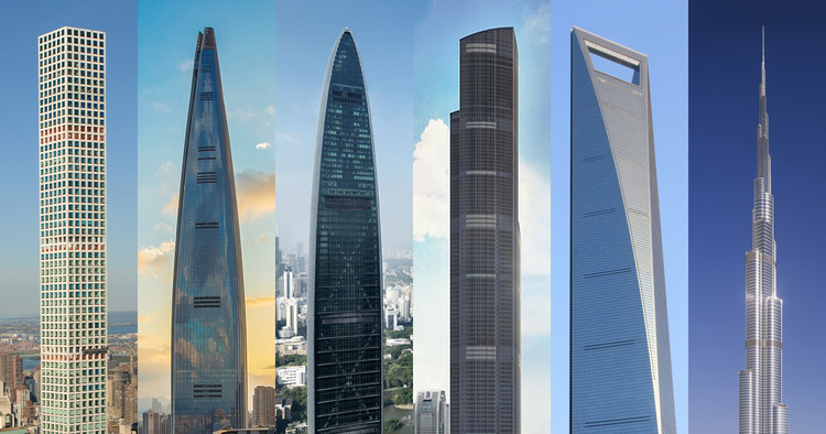
The year 1885 can best be identified and credited to mark the change in the course of tall structures. It was the year the Home Insurance Building – the first tower block was completed in Chicago (see featured image). It was framed in structural steel, had 10 storey of office spaces and stood 42m tall. Up until this time the tallest structures, in the world were either religious centre, castles or palaces. This new technology soon spread to major cities of the world and soon the Home Insurance Building would be quickly eclipsed by subsequent structures. However, as the drive to build even more tall structures increased, came an issue of crucial concern: the vertical deformation of vertical load bearing structural elements known as axial shortening.
This article discusses axial shortening and its causes, how they can be predicted, evaluated and mitigated. It would explain the measures structural engineers and building contractors may employ to counter its effect. It would also make references to the current codes of practices were necessary.
Axial Shortening
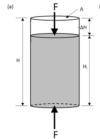
To understand the concept of axial shortening, one has to go back to the concept of stress and strain as it applies to structural elements. The stress strain behaviour is best explained using Hooke’s law which states that “Stress is directly proportional to Strain”. Practically speaking, if an axial compressive load F is applied on an element, it would be stressed and as a result will undergo a deformation in the form of a strain (Figure 1). The magnitude of the strain it undergoes is directly equivalent to the magnitude of the stress applied.
In more practical sense, vertical elements in structures under loading are also stressed hence they undergo some vertical deformation as soon as they are constructed. It is this vertical deformation that is known as axial shortening. In tall buildings, these vertical load bearing elements carry enormous loads it therefore follows that the vertical deformation would become even significant as the number of storey increases. Albeit, axial shortening occurs in all structures, regardless of height and storey. However, it only becomes a major problem when a building structure is more than 15 storey, also depending on the structural layout, structural system and the geometrical properties of the structural elements present in the structure.
Causes of Axial Shortening
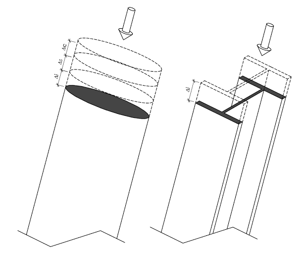
The principal cause of axial shortening of structures is as discussed above – axial strain in other words vertical deformation from application of a sustained load. All materials do exhibit some axial shortening however, the behaviour is more pronounced in timber frames and most pronounced in reinforced concrete. Assessing the behaviour of concrete structures to axial shortening is particularly very complex being a composite material. The effects of creep and shrinkage must in addition to axial strain be considered when predicting the magnitude of the axial shortening in reinforced concrete (Figure 2).
Shrinkage & Creep
The shrinkage of concrete is an important variable in assessing the axial shortening of vertical elements in concrete structures. Shrinkage is a property of concrete that occurs during the curing stage, as it dries and solidifies. There are different types of shrinkages as it applies to reinforced concrete, but the best description that fits this context is a volumetric change due to the loss of moisture by evaporation and drying.
Reinforced concrete is a composite material; thus, the resulting shrinkage depends on the bond between the steel and concrete. Built in stresses are often transferred from the concrete and steel. And since steel has a much greater modulus of elasticity compared with concrete the result is a reduction in the amount of shrinkage that would otherwise have occurred in the absence of any reinforcement.
Creep is another important parameter in the estimation of axial shortening in concrete structures. It can be defined as the shortening of an element from the application of a persistent load with time.
Whilst the bulk of the axial shortening effects from shrinkage already occurred within few hours of pouring concrete, a concrete structure will not stop to settle until the close of the life span of the structure. Aside this fact, it’s often the case that shrinkage can be managed by controlling temperature that would otherwise leads to volumetric change by enclosing the structure with a façade. This therefore implies that the predominant factor causing shortening is creep. In reinforced concrete structures, creep occurs within the vertical support system, such as columns and walls, causing shortening throughout the lifespan of the structure.
Many factors, both internal and external impacts on the magnitude of creep, having an encompassing consequence on the value of axial shortening. These include the properties of the concrete, the geometrical properties of the vertical element and the environment in which the concrete is being poured.
Creep and shrinkage effects must be considered in the assessment of axial shortening of concrete structures. They’re a very significant and intricate behaviour grossly affected by time dependent variables. A thorough discussion of the above will go beyond the scope of this article, hence designers assessing concrete structures for axial shortening are advised to consider the texts in the ‘sources and citation’ section of this article.
Evaluating Axial Shortening
Assessing structures for axial shortening is a very complex endeavour. Perhaps, even more complicated for reinforced concrete structures due to the number of variables that must be considered. In a typical reinforced concrete building, estimating the values of axial shortening requires a very sound and detailed understanding of how the structure contracts throughout the intending life span of the structure. What is the magnitude of the axial strain? What are the expected values of the shrinkages and creep?
It must be noticed that this article has a focus on creep and shrinkage in explaining the causes and mitigation strategies employed in addressing axial shortening. Whilst vertical elements in steel buildings are only susceptible to axial strain, those in reinforced concrete are subjected to a combination of axial, shrinkage and creep shortenings (Figure 2). Hence, it’s safe to say this article discusses axial shortening with a focus on reinforced concrete structures. Although steel and timber buildings have gained a lot of tractions in the design of tall buildings, reinforced concrete still remains the favourite. Even where a steel or timber frame is the structural solution, the lateral stability system (core) is done in concrete.
According to BS EN 1992, there are three variables impacting the magnitude of creep and shrinkage in a reinforced concrete structure. These are; the relative humidity of the ambient environment in which the concrete was poured, the geometrical properties of the concerned elements and the properties of the concrete mix.
BS EN 1992 provides guidance on how to estimate creep and shrinkage in reinforced concrete structures (See section 3.1.4 and Annex B). Estimating creep and shrinkage using the procedures detailed in the code requires the use of spreadsheets. The method given relies on sophisticated computational tools in providing a reasonable accurate model of the magnitude of axial shortening. See section of the code for procedures on how to estimate creep and shrinkage, a detailed explanation would go beyond the scope of this article.
These days, most structural design packages now permit a ‘staged construction analyses. A staged construction analysis is a procedure that allows a structure to be built virtually in real time and loaded sequentially in accordance to an anticipated construction sequence, allowing for the effects of axial strain, shrinkage and creep to be fully cognized. The usefulness of this type of analysis is that it allows for the development of these effects over time. And also, the fact that it provides insights into the magnitude of the movements which will occur during construction, at the point of installing building components and throughout the lifespan of the building.
However, even with the most sophisticated software packages, movement in practice could differ from those predicted due to the complexity in establishing in actual sense the values of the variables influencing creep and shrinkage. Hence, it is advisable to always validate the models, check out the behaviour and properties at the upper bound and lower bound attributes to fully access and understand the full range of the movement.
In evaluating the effects of axial shortening on structures using the procedures giving in BS EN 1992-1-1, the following rules of thump becomes very applicable in examining the results obtained from a software package. Here are the points to note:
- Taking into account the effect of shrinkage and creep, vertical elements in concrete structures typically move by approx. 1mm/m.
- The use of elements with the same geometrical properties, but having a different concrete strength and reinforcing steel, alters the magnitude of the overall axial shortening in a structure.
- The larger the cross-sectional area of the vertical element, the lesser the axial movement possible.
- Increasing the overall concrete strength of a structure will reduce the magnitude of the axial shortening it undergoes
- Increasing the amount of reinforcement in vertical elements while maintaining the cross-section size will reduce axial shortening.
Mitigating Axial Shortening in Tall Buildings
As must’ve being stated in one of the preceding sections, axial shortening is not a major concern in buildings of less than 15 storey. However, talking about tall and super-tall structures axial shortening is a cause of major concern especially where non-structural elements such as partitions, façade, ceilings and other building components are to be incorporated. Most of the above-listed elements, aside being designed to achieve a in-tight construction are very brittle in nature. Hence, there is need for certain allowances in the building design.
Delaying the installation of brittle non-structural finishes, notably the claddings, thus allowing for more movement prior to installation is one of the means through which the effects of axial shortening can be alleviated. However, dealing with axial shortening in tall structures requires more attention beyond just delaying the installation of few building components, the designers should have reports highlighting the creep components that is likely to occur upon attaching these elements.
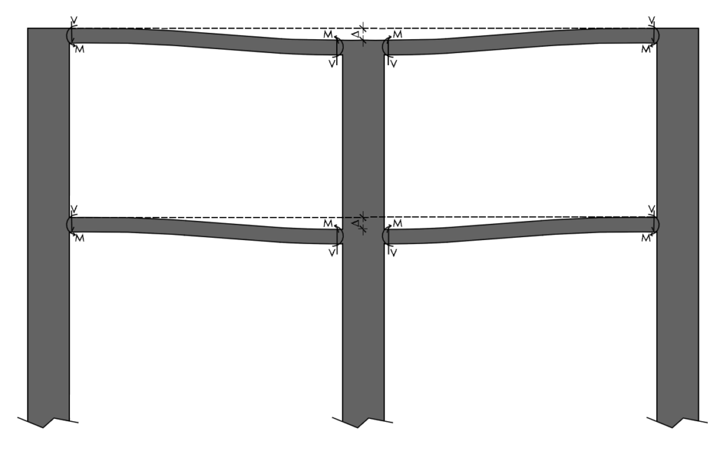
Also of importance is the potential for differential axial shortening between adjacent vertical elements with significantly different geometry. For example, the movement of a concrete core in a tall building would most definitely be different from that of an isolated column. In instances where these elements are closely spaced together, the horizontal elements connecting them could experience significant rotation (Figure 3). Hence it is also good practice in the design of tall buildings against axial shortening to space vertical elements sufficiently apart from each other.
It is possible to mitigate axial shortening in tall buildings by altering the material composition of the vertical elements. For example, by increasing the reinforcement in a column or the strength of the concrete while retaining the same size throughout its length, it is possible to reduce creep that would occur between the steel and concrete. However, this is not always practical giving the strict detailing requirement of vertical elements in BS EN 1992 in addition to problems of economy, material efficiency and now structural embodied carbon.
It is also possible to reduce axial shortening by limiting the stress applied unto vertical support elements by optimizing their size, location, and number, thereby reducing the amount of axial shortening they exhibit.
One approach is to predict the amount of axial shortening that will occur in the structure and then pre-set the horizontal elements that are to be supported on a relatively higher level. This is a very useful approach especially when the vertical elements present in the structure have a very large cross-section and are more susceptible to axial shortening. But this method is not often used due to the uncertainty involved with estimating the vertical movements.
Another approach towards achieving these would be to have horizontal elements have rigid connections between the core walls and the columns that are most likely to be impacted by axial shortening. These horizontal elements can then assist in limiting the axial shortening, however, they must be designed for the increased designed actions as a consequence of the movement.
Lastly, the stress that builds up in a column or core wall in a tall building can be relieved through the use of a ‘belt truss’. A belt truss is a storey height perimeter truss constructed around the frame of a tall building (See figure 4). The usefulness of a belt truss is that it has the effect of minimizing uplifts since the columns forming the perimeter truss must now resist tension and compression due to the presence of a truss.
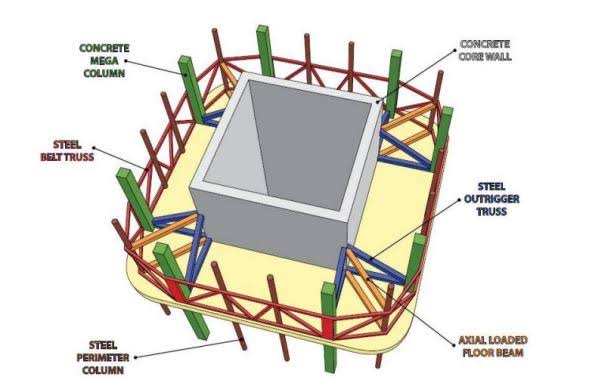
The primary benefit of a belt truss in tall buildings is often to work with the shear core and outriggers towards stiffening the whole structure. However, an added benefits is in reducing the effect of axial shortening.
See: Fundamentals of Tall Building Design
Sources & Citation
- Regan C.O (2021) ‘Axial Shortening’, The Structural Engineer -Technical Guidance Note (level 3) 99(1), pp. 24-28.
- Fu F. (2018) Design and analysis of tall and complex structures, Oxford: Butterworth–Heinemann
- Kim H. and Shin S. (2014) ‘Reduction of differential column shortening in tall buildings’, Int. J. Civil Environ. Struct. Construct. Arch. Eng., 8 (2), pp.145–148
- Fintel M., Ghosh S.K. and Iyengar H. (2005) Column shortening in tall structures – prediction and compensation, Skokie, Il: Portland Cement Association
- BS EN 1992-1-1:2004+A1:2014 Eurocode 2: Design of Concrete Structures. General Rules and Rules for Buildings
Thank You!