This explores the design consideration and distinctions that exists when designing composite steel structures that utilizes precast concrete unit in place of in-situ concrete for flooring.
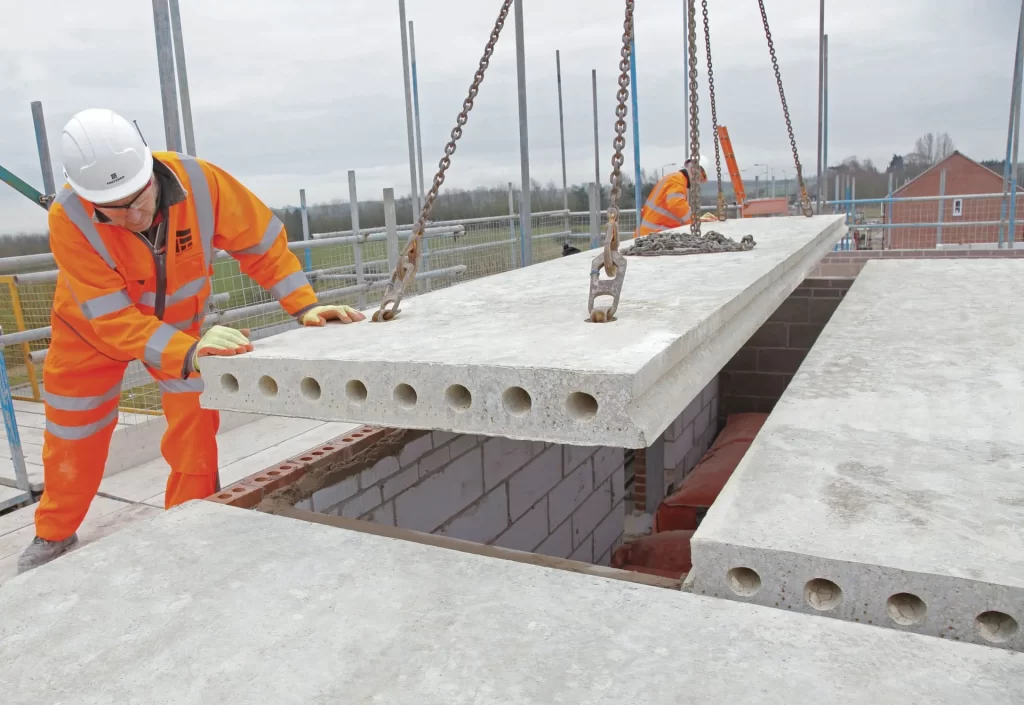
The last two articles on the design of composite structures have focused on composite structures and slabs in which the concrete element is cast in situ. However, you can also create the concrete flange of a composite beam using precast units, whether they are solid or hollow core. This construction method is particularly suitable in certain situations and also showcases the typical benefits of composite construction, such as reducing the weight and depth of steel beams.
However, to be more specific, using precast units can facilitate greater spacing of secondary beams and efficient use of composite construction in semi-exposed applications, such as car parks. If no concrete topping is required, the ‘dry construction’ method can expedite on-site work. Although profiled decking reduces the crane time needed to construct a floor (since individual sheets can be manually placed), precast units provide the benefit of a more robust floor immediately upon installation.
Composite beams with precast units are not currently covered by Eurocode 4, and the rules in that code, particularly those regarding effective flange width, stud resistance, and minimum degree of shear connection, cannot be applied blindly to this form of construction. Thus, this article provides complementary guidance and justification, focusing solely on precast units used with down stand beams. The ‘Further reading’ section includes a publication that discusses shallow floors using precast units.
Effective Flange
Recall that in the design of composite structures, the effective flange is a very critical parameter that influences on the member resistances. The first distinction between the design of composite structures cast in-situ and those made from precast is the effective flange. For precast units, the effective flange depends on the type of precast unit in question – either hollow core units or solid planks.
Hollow-core Units
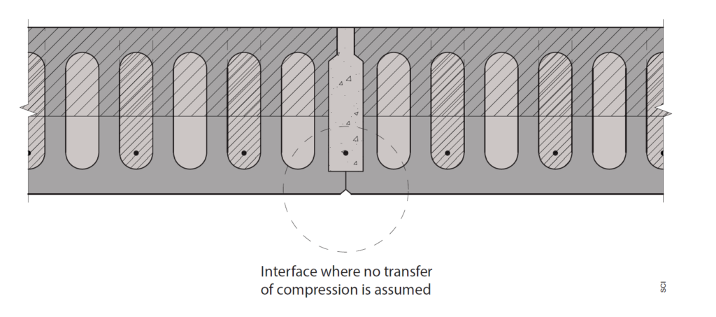
For hollow-core units, the extent of the in-situ concrete and the area of transverse reinforcement (bars passing between opposing units, as shown in Figure 1) will significantly influence the effective width of the slab considered in the composite beam design. Research has shown that the effective width of the slab should not exceed the total width of the concrete infill plus the width of the gap between the ends of the hollow-core units. This dimension is typically less than 1.5m, with bars extending between 500mm and 600mm into the units depending on fire design requirements. Tests have justified that the full depth of concrete is mobilized within this width. Since all of the effective flange is in close proximity to the beam, any reduction in the depth of in-situ topping (due to pre-cambering of the hollow-core units) will not negatively impact structural performance.
Solid planks
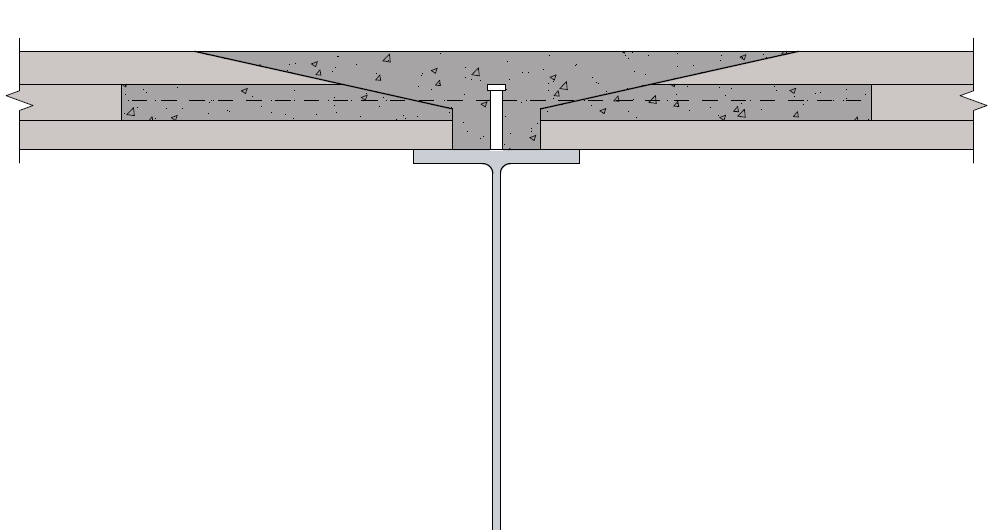
Since more in-situ concrete topping is used with solid planks compared to hollow-core units, the effective width can be calculated similarly to a composite beam with an in-situ slab. EN 1994-1-1 Clause 5.4.1.21 expresses the effective width in relation to the span of the beam. Different values may apply at various points along the beam, but when using elastic global analysis, a constant effective width can be assumed over the entire span, taken as span/4.
Solid planks placed transversely to the beam can be considered to act in compression if the edge details allow the transfer of compression through in-situ concrete. In such cases, at least 25mm of the slab depth should be deducted due to the absence of in-situ concrete at the interface between the bottom edges of the planks, as shown in Figure 2 for hollow-cores. If there is a simple butt joint detail between the planks, effective compression transfer is not achieved, and the slab depth should be considered as the depth of the concrete topping alone. Note that in this scenario, the structural characteristics of the composite beam will be sensitive to the depth of the in-situ topping, and care should be taken to account for any reductions in this depth due to pre-cambering of the precast units.
Shear Connections
The next distinction between in-situ composite construction and the use of precast unit is with the design of shear connections. The distinctions as it relates to shear connections are expatiated in the following sub-sections.
Resistance of shear studs
Eurocode 4, like BS 5950-3.12, defines the resistance of a shear stud in a solid concrete slab (Clause 6.6.3.1) and provides reduction factors kt and kl to apply to this resistance when the slab is formed using profiled steel decking, whether transverse or parallel to the beam axis. These reduction factors are based on tests involving slabs of the relevant form. A similar approach must be used to determine reduction factors for slabs made of solid or hollow-core precast units, which can then be justifiably applied to the solid slab resistances specified in EN 1994-1-1.
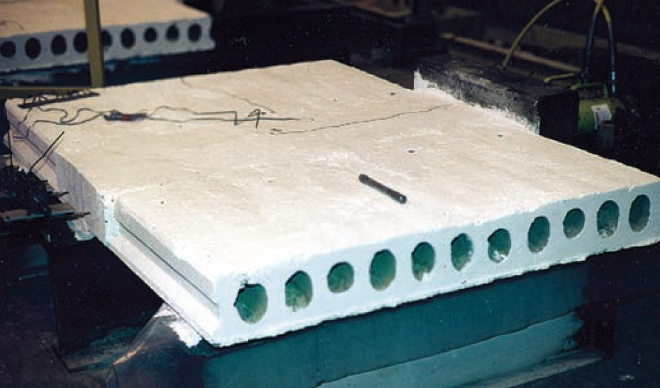
For hollow-core units, the reduction factor k is based on push-out tests conducted by Lam (Figure 3). It depends on the gap between the plank ends and the confinement of the stud within that gap, which is reinforced, and can be taken as 0.9 if the detailing rules on minimum gap width and bar size in the following subsections are followed (more details are available in the forthcoming SCI publication, P401: Design of Composite Beams Using Precast Concrete Slabs in Accordance with Eurocode 4).
Tests have shown that the reduction factor for studs embedded in slabs with solid planks only depends on the gap between the solid planks. A value of k equal to 1.0 can be used when there is a sufficient gap to ensure proper compaction of the concrete.
Minimum degree of shear connection
Clause 6.6.1.2 of EN 1994-1-1 provides minimum shear connection rules to ensure that shear studs have adequate deformation capacity, based on a characteristic slip capacity of 6mm. These rules ensure the connection is stiff enough to prevent excessive slip. To accommodate 6mm slip and justify using these rules for slabs with precast units, employ 16mm diameter high tensile transverse reinforcement bars (passing between opposing units) for hollow-core units. Place the bars at least 15mm below the heads of the studs (Figure 3). This placement is generally feasible because studs are typically 125mm high, and the base of the opening is 30-40mm above the base of a hollow-core unit. For solid planks, use bars of at least 10mm diameter, along with A142 fabric, to maintain the 6mm slip capacity.
Other Special Considerations
There are some other special considerations that should be considered when designing composite floors with precast units. This relates to minimum top flange width, restraint of the steel beam and loading during construction. These are briefly expatiated below.
Minimum Top Flange Width
The minimum acceptable width of the beam’s top flange depends on the type of slab, whether the shear connectors are shop-welded or site-welded, and whether the beam is internal or on the edge. This specification ensures that the precast units have sufficient bearing (Figure 4) and that the shear studs can be correctly placed and embedded in concrete. The chosen width must also account for manufacturing and construction deviations, including variations in steelwork size and position, precast unit length variations, and the accuracy of unit placement on site. While it is possible to quantify each of these factors separately with time and effort, a simple summation would be excessively conservative. Instead, consider a global overview of how these deviations might reasonably combine.
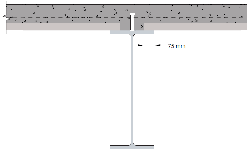
Using the above approach, The Precast Flooring Federation recommends a minimum nominal bearing length of 75mm. Besides ensuring adequate bearing for the units, there must also be a sufficient gap between them. Typically, a minimum of 85mm is recommended for site-welded shear connectors to allow space for the welding tool and concrete placement (65mm), while accommodating up to 10mm of excess bearing of the precast units on each side. For shop-welded shear connectors, this gap can be reduced to 70mm, as only 50mm is needed for concrete placement.
Consequently, the minimum beam flange width should be 235mm for site-welded studs or 220mm for shop-welded studs. It might be feasible to use a steel section with a narrower flange, especially for supporting shorter span precast units, if manufacturing and site deviations can be controlled within tighter tolerances. However, this should only be done in consultation with the precast supplier.
Loading During Construction
When verifying the bare steel beam, two distinct conditions must be considered. Firstly, during the construction phase when the precast units are installed, the beam may experience significant unbalanced loading, depending on the sequence of placement and the span of the units on either side. This unbalanced loading can subject the beam to combined bending and torsion, necessitating cross-section and member verifications.
Secondly, once all units are in place, including any in-situ topping and variable construction loads, the beam must be verified again. During this stage, if the precast units on either side have equal spans, the beam will be checked for balanced loading. There’s no need to consider ‘pattern loading’ with construction loads placed on one side only.
Restraint of the steel beam
When the slab is formed from in-situ concrete, the top flange of the steel beam is typically restrained during construction. This can be achieved either by adequately fixed decking spanning transversely to the beam, providing in-plane stiffness, or by secondary beams supporting longitudinal decking at 3-4m intervals.
In the case of precast units, if they have equal spans on either side of the beam, they can be assumed to provide restraint through a combination of restoring moment (Figure 5) and friction for beam spans up to 160 times the unit’s bearing width. This means spans up to approximately 8m may be assumed to be restrained. If the top flange cannot be assumed to be held in place by the units, specific restraints must be provided. These restraints should be capable of resisting a force equal to 2.0% of the force in the compression flange.

In addition to the potential necessity of providing structural restraint to the beam to prevent torsional modes of failure, temporary restraints may be required to hold the top flange in position during the placement of precast units. The specific need will depend on several variables, particularly the lateral stiffness of the beam. A commonly recognized rule-of-thumb suggests placing ties between compression flanges at a minimum spacing of 40 times the beam flange width.
Also See: Construction of Composite Floors
Sources & Citations
- Steel Construction Institute (2014) Design of composite beams using precast concrete slabs in accordance with Eurocode 4 (P401) Ascot, Berkshire: SCI (publication in 2014)
- Steel Construction Institute (2006) Design of asymmetric Slimflor beams with precast concrete slabs (P342) Ascot, Berkshire: SCI
- Institution of Structural Engineers (2014 (2014) Composite beams using precast units, Composite & Steel Construction Compendium. The Structural Engineer
- British Standards Institution (2005) BS EN 1994-1-1:2004 Eurocode 4. Design of composite steel and concrete structures – General rules and rules for buildings London: BSI
- Precast Flooring Federation (2013) Code of Practice for: The Safe Installation of Precast Concrete Flooring and Associated Components [Online] Available at: www.precastfloors.info/downloads/download-registration.html (Accessed: May 2024)