This article gives an overview of the analysis and design of box culverts, the checks and verifications required to be carried out, including a worked example to the Eurocodes.
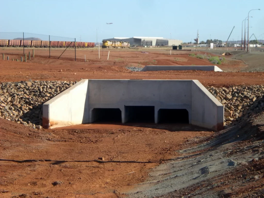
Recall that the design of a box culvert has two parts – hydrological aspects and structural aspect. The hydrological aspect is the foremost consideration has stated in the preceding article. Having considered the hydrological aspect of designing the box culvert, which has to do with determining the size of the culvert that is able to accommodate the peak flood discharge throughout the proposed service life of the culvert, the culvert designer can proceed to the structural aspect.
The structural aspect basically involves estimating the magnitude of the loads that the culvert is expected to sustain throughout the design life, ensuring that the size and thickness of the culvert walls and slabs are appropriate to support these loads. And then providing the quantity of reinforcement required in the culvert walls and slab.
Eurocodes outline procedures for determining these loads which involves meticulously calculating traffic loadings, the self-weight of the box culvert, lateral forces, and vertical forces from soil, among others. This have been clearly outlines in a previous article (See: How to Apply Loads on Box Culverts). Thus, this article is only concerned with how to determine the design forces towards providing the reinforcing steel required in the culvert slabs and walls. These is done in accordance with the Eurocodes.
Structural Analysis of Culvert
This involves analyzing the box culvert for the applied loads in order to determine the design forces. But before structural analysis can be conducted, partial factors are required to be applied to the loads depending on whether they occur as permanent actions or variable actions. When working to the Eurocode, this is defined in Clause A.2 of BS EN 1991. A factor of 1.35 is applied to all permanent actions while for the variable actions 1.5 is applied to all variable actions.
In analyzing the box culvert, two loading scenario is required ideally to be considered. First, where the box culvert is empty, the lateral earth and surcharge pressure applied on the walls and the full traffic load on the top slab. The second load scenario envisages that the culvert is full of flowing water and there is no traffic load on the top slab. For most culvert load scenario 1 governs the design, hence it is considered for design purposes.
Having determined the design value of the applied loads, the box culvert is analyzed as a rigid frame. Thus, any of the methods of analyzing a statically indeterminate structure is applicable, such as the Hardy Cross moment distribution, slope-deflection methods, three moments Clapeyron equation etc. Guidance on how to analyze a frame can be obtained from the following article (See: How to Analyse Element in Frames.).
Structural Design of Culvert
Three types of forces are determined from the structural analysis – bending moment, shear and axial pull.
Bending & Axial Force
In providing the reinforcement, an interaction of flexure and axial force need to be considered. This is primarily due to the interconnection of the members which allows the culvert walls exert axial forces into the culvert slabs and vice versa. Thus, each element is designed for an interaction of bending with axial force in the same manner as envisaged for a column subjected to axial load and bending moment using the column interaction charts.
Th two expressions presented below are required to read the charts in order to determine the area of steel required. Recall that the charts are based on a ratio of effective depth to overall depth.
\frac{N_{Ed}}{bhf_{ck}} \quad \& \quad\frac{M_{Ed}}{bh^2f_{ck}}Where: NEd and MEd are the design axial force and bending moment in the culvert slab or wall respectively; b & h is the width and overall depth of the culvert slab or wall respectively and fck is the characteristics strength of concrete.
Shear
Shear tends to be more critical in the slabs than walls, thus shear verification is required for the top and bottom slabs. However, shear reinforcement is mostly undesired in solid slabs, hence it is always advisable to limit the applied shear stress to the shear resistance of the culvert section, so that shear reinforcement is not required. This requires that the following expression is satisfied.
V_{Rd,c}\le V_{Ed}Where: VEd is the design shear force; and VRd,c is the concrete design shear strength.
Steps in Designing a Box Culvert
- Determine the design loads by applying the appropriate partial factors to the applied loads.
- Consider the culvert as a rigid frame and analyze the culvert to obtain the design bending moment, shear force and axial force in the culvert slabs and walls using any of the methods of analyzing indeterminate structures.
- Having obtained the design forces, use the axial forces and the corresponding moment to determine the quantities of steel required in the culvert walls and slabs.
- Verify that shear reinforcement is not required in the culvert, else section thickness should be increased or shear reinforcement should be provided.
Worked Example
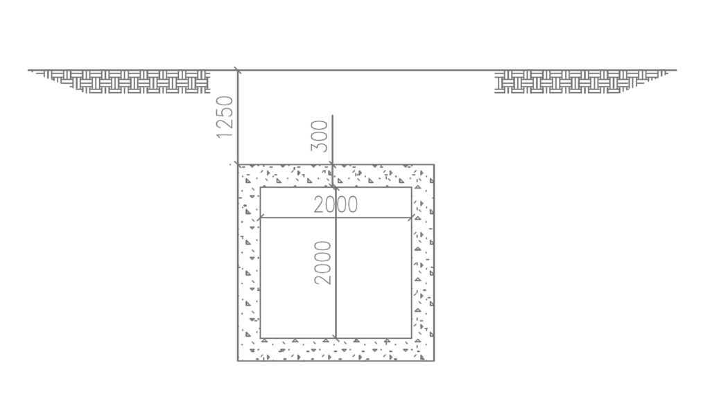
Determine the quantities of steel required in a culvert in a roadway corridor using the following parameters. The top slab of the culvert is required to sustain a fill of 1.25m thick fill on the culvert before the carriageway and an asphaltic layer of 75mm. The culvert has a carriageway of 7.3m. The width of the culvert walls is 3.0m and the thickness of the culvert is 300mm. Assume the backfill soil has an internal friction angle and base density of 30° and a base density of 18kN/m³, the unit weight of asphalt concrete is 22kN/m³, and that of reinforced concrete is 25kN/m³. Use C45/50 Concrete and 500Mpa Steel.
Recall that the load applied on this culvert was determined in the previous article (See: How to Apply Loads on Box Culverts). In this article the process of estimating these loads is not repeated but the values presented.
Design Value of Actions
A factor of 1.35 is applied to all permanent actions while for the variable actions 1.5 is applied to all variable actions.
Vertical Actions – Top Slab
n_{s,vertical} =1.35g_k +1.5q_k \\=1.35(31.7)+1.5(69.1)\\= 146.5kN/m^2Lateral Actions – Walls
n_{s,lateral,min} =1.35g_k+1.5q_k \\= 1.35(11.25)+1.5(2.5)\\=18.95kN/m^2n_{s,lateral,max} =1.35g_k+1.5q_k \\= 1.35(34.7)+1.5(2.5)\\=50.6kN/m^2Vertical Actions – Bottom Slab
The load applied to the bottom slab includes the load from the top slab and the weight of the culvert walls.
- Weight of walls:
1.35\times 2(0.3\times2.0\times\times25)/2 =10.1kN/m^2
n_{s,v} =146.5+10.1=156.6kN/m^2
Having obtained the design values of forces on the culvert elements, we can proceed to the structural analysis of the culvert.
Structural Analysis of Culvert
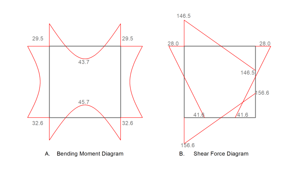
Analysis of the Frame shown in figure 3 is carried out using the moment distribution method to determine the bending moment, shear force and axial forces in the culvert elements. How to do this has been covered in a previous article (See: Analysis using Moment Distribution). Here, only the bending moment diagram and shear force diagram so obtained is presented. (See Figures 4 & 5.
Reinforcement Design
By inspecting the bending moment and shear-force diagrams presented in figure 3 above, we can see that the maximum values occur at the midspan for the slab and at the interface of the slab-wall for the walls. Also notice that there is an axial force in the culvert elements as envisaged. Thus, the maximum values are used to provide the reinforcement required in each element. See table 1 for Values.
| Member | Bending Moment (kN.m) | Shear Force (kN) |
| Top Slab | 43.7 | 28.0 |
| Bottom Slab | 45.7 | 41.6 |
| Walls | 32.6 | 156.6 |
Top Slab
Assuming cover to reinforcement of 25mm, 16mm tensile bars, the effective depth of section:
d=h-(c_{nom}+\phi/2) =300-(30+16/2)\\=262mm\frac{d}{h}= \frac{262}{300}= 0.87Thus, we can use column interaction charts of 0.85.
\frac{N_{Ed}}{bhf_{ck}} =\frac{28.0\times10^3}{10^3\times300\times45}=0.0018\frac{M_{Ed}}{bh^2f_{ck}} =\frac{43.7\times10^6}{10^3\times300^2\times45}=0.01By inspection, minimum area of steel will govern the design, thus:
A_{s,min}=\frac{0.1N_{Ed}}{f_{yk}} \ge0.002A_c=\frac{0.1\times28.0\times10^3}{500}\ge0.002\times 10^3\times300 \\=600mm^2/mProvide Y12 – 150mm Centers (As,prov = 753mm2/m) – Each Face
Bottom Slab
\frac{N_{Ed}}{bhf_{ck}} =\frac{41.6\times10^3}{10^3\times300\times45}=0.003\frac{M_{Ed}}{bh^2f_{ck}} =\frac{45.7\times10^6}{10^3\times300^2\times45}=0.012Again, minimum area of steel governs the design. thus:
A_{s,min}=\frac{0.1N_{Ed}}{f_{yk}} \ge0.002A_c=\frac{0.1\times41.6\times10^3}{500}\ge0.002\times 10^3\times300 \\=600mm^2/mProvide Y12 – 150mm Centers (As,prov = 753mm2/m) – Each Face
Walls
\frac{N_{Ed}}{bhf_{ck}} =\frac{156.6\times10^3}{10^3\times300\times45}=0.012\frac{M_{Ed}}{bh^2f_{ck}} =\frac{32.6\times10^6}{10^3\times300^2\times45}=0.009Again, minimum area of steel governs the design. thus:
A_{s,min}=\frac{0.1N_{Ed}}{f_{yk}} \ge0.002A_c=\frac{0.1\times156.6\times10^3}{500}\ge0.002\times 10^3\times300\\ =600mm^2/mProvide Y12 – 150mm Centers (As,prov = 753mm2/m) – Each Face
Shear Verification
By inspection, the critical section for shear occurs in the bottom slab (VEd =156.6kN), hence, this can be used to verify the adequacy of the section in shear.
V_{Ed} \le V_{Rd,c}V_{Rd,c} =0.12k(100\rho f_{ck})^{1/3}bd \\\ge 0.035k^{3/2} \sqrt f_{ck}bdk =1+ \sqrt \frac{200}{262} = 1.87\rho =\frac{A_s}{bd} =\frac{1340}{10^3\times262} =0.51\% =0.12\times 1.87(0.51 \times 45)^{1/3}bd \\\ge 0.035\times 1.87^{3/2} \sqrt 45bdV_{Rd,c}= 157.3kN > (V_{Ed}=156.6kN)Design Resume
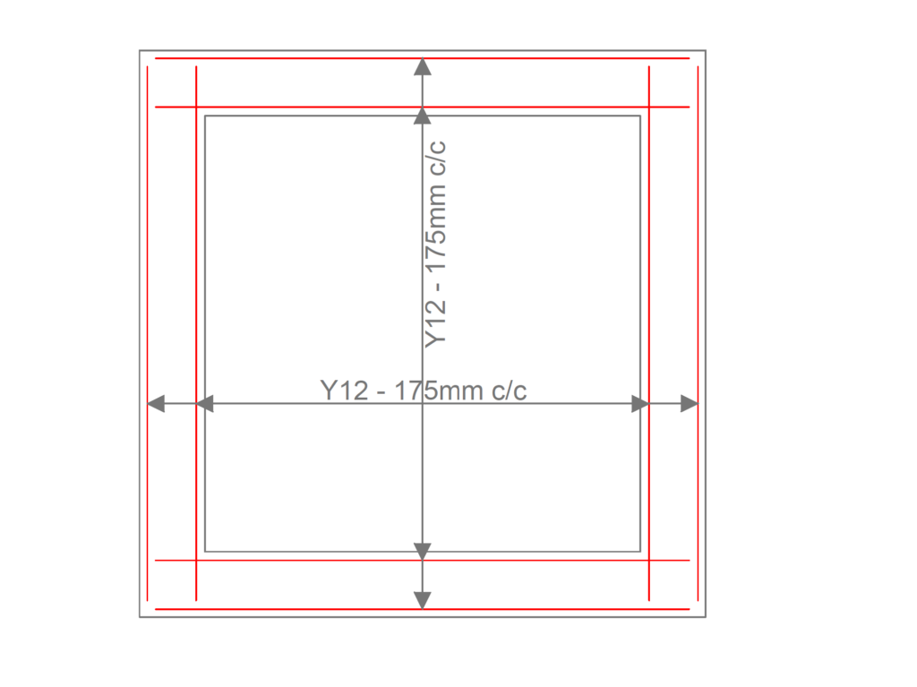
The section provided below in figure shows summary of the reinforcement details of the box culvert. When preparing the final detailed drawing, distribution rebars are provided based on the minimum area of steel.
See: Design Standards for Box Culverts to Eurocode
Sources & Citations
- BS EN 1992-1-1:2002 – Eurocode 2: Design of concrete structures – Part 1-1: General rules and rules for buildings
- Oyenuga, V. O. (2001), “Simplified Reinforced Concrete Design”. Agros Limited, Lagos, Nigeria. PP415.