This article explores the plate load test and illustrates how to use data obtained during the test to determine the bearing capacity of soils.
The plate load test is a method of measuring the bearing capacity of soils in-situ. Field methods of estimating bearing capacity is sometimes preferred over the laboratory for certain reasons. Firstly, as the name suggest, field methods offer site-specific, in-situ assessments, considering soil composition, moisture, and dynamic loading. Secondly, they provide real-time data efficiently and cost-effectively, enhancing foundation design accuracy. Thirdly, In-situ testing is able to relatively capture soil behavior accurately, considering natural conditions without sample transportation.
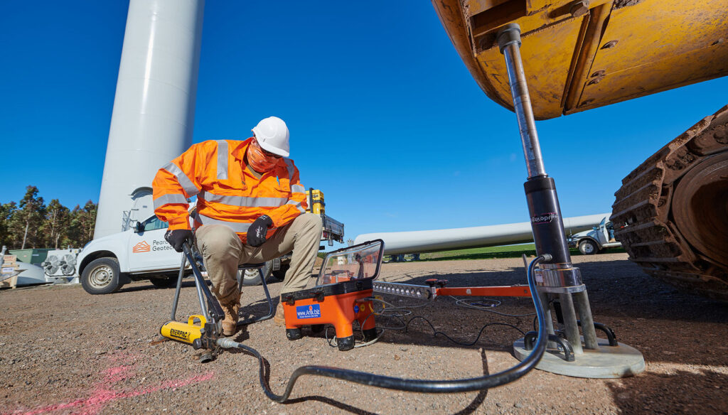
The plate load test is one of the most useful field methods of measuring the bearing capacity of soils. A typical plate load test sees a rigid plate of known dimensions placed on the ground, and a load from a machine is applied incrementally (See Featured Image). This load causes consolidation of the soil mass and as a result the plate settles. The settlement of the plate is then measured incrementally, and thus the bearing capacity of the soil can be calculated by relating applied loads with settlements.
Plate Load Test
To put it even better, the process involves applying increasing loads to a rigid plate positioned at the foundation level in incremental steps. Each load increment’s corresponding settlement is measured using at least two or three dial gauges, each with a minimum reading accuracy of 0.02 mm, positioned separately at 120° or 90° angles. The test load is progressively augmented until the plate exhibits significant settlement. By plotting the load-settlement curve, engineers can determine both the settlement and bearing capacity of the soil.
The ultimate bearing capacity of the soil is calculated by dividing the total load applied to the plate by its area. To ascertain the safe bearing capacity of the soil, a factor of safety is then applied to this value.
Factors Affecting the Accuracy of the Plate Load Test
While field methods of estimating soil bearing capacity is considered relatively accuracy when compared with the laboratory methods, there are factors that may affect the quality and accuracy of the result obtained. Thus, in order to derive a realistic value these factors must be considered.
Plate Size and Shape
Plate size and shape are pivotal factors in plate load testing, they dictate the stress distribution within the soil. Larger plates disperse the load across a broader area, fostering a more uniform stress distribution and potentially yielding lower bearing capacities. Conversely, smaller plates concentrate the load into a smaller area, resulting in heightened stress concentrations and potentially higher bearing capacities. Additionally, the plate’s shape—whether square, circular, or rectangular—also influences stress distribution and should be chosen judiciously to align with the project site’s specific requirements and soil conditions.
Testing Depth
The depth at which the plate is positioned holds considerable sway over the soil properties encountered in the test. Shallow placement may fail to accurately portray the bearing capacity of deeper soil layers, particularly in scenarios featuring layered or heterogeneous soil profiles. Conversely, deeper placement permits the assessment of soil properties at greater depths, facilitating a more comprehensive grasp of soil behavior and bearing capacity. Accordingly, the testing depth ought to be determined based on the anticipated foundation depth and prevailing soil conditions at the project site to guarantee representative results.
Testing Procedure
Differences in testing procedures, encompassing loading rates, durations, and sequencing, wield significant influence over soil behavior and test outcomes. Swift loading rates might trigger excessive settlement or failure, whereas leisurely loading rates might inadequately mobilize the soil’s bearing capacity. Adherence to standardized testing protocols is imperative to uphold consistency and precision in test outcomes. Deliberate attention should be accorded to the sequence of loading and unloading to circumvent soil overloading or overstressing, while simultaneously capturing both immediate and protracted settlement behavior.
Soil Disturbance
Construction activities, nearby excavations, or previous tests in proximity can disrupt the soil and influence plate load test outcomes. Soil disturbance engenders alterations in soil properties and stress distribution, thereby jeopardizing the accuracy of soil bearing capacity assessments. Prior to conducting plate load tests, it is imperative to undertake thorough site investigations and assessments to pinpoint and mitigate potential sources of soil disturbance. Consequently, test locations should be chosen distant from recent construction or excavation zones to mitigate soil disturbance and ensure the integrity of test results.
Environmental Conditions
Environmental factors, including moisture content, temperature, and seasonal fluctuations, exert notable influence on soil behavior and test results. Moisture content impacts soil strength and compressibility, with higher moisture levels typically correlating with diminished bearing capacities compared to drier soils. Temperature fluctuations induce expansion or contraction of soil particles, thereby altering soil density and stiffness. Seasonal changes in groundwater levels and soil moisture content further influence soil properties and settlement behavior. To ensure the accuracy and reliability of plate load test results, tests should be conducted under representative environmental conditions, with adjustments made to account for factors such as moisture content and temperature variations.
Procedure for Conducting a Plate Load Test
The procedure for conducting a plate load test is well defined in part 9 of BS 1377. This is reproduced under the following steps in this article.
Site Preparation
Clear the test area of any debris, vegetation, or loose soil to create a stable testing surface. Ensure that the area is level and free from any obstructions.
Plate Installation
Position the steel plate, typically square or circular, on the ground surface at the desired test location. The plate should have a diameter ranging from 300 mm to 750 mm, depending on the project requirements. Ensure that the plate is centered and firmly seated on the soil surface.
Instrumentation Setup
Install at least two or three dial gauges around the perimeter of the plate, spaced evenly apart. These gauges should have a least count of 0.02 mm. Position the gauges separately at angles of 120° or 90° around the plate, ensuring accurate measurement of settlements.
Loading
Apply a gradually increasing load to the plate using a hydraulic jack or other suitable loading equipment. The load should be applied in arbitrary increments, with settlements recorded at each load increment. Increase the load gradually until the plate exhibits significant settlement.
Settlement Measurement
Record the settlements corresponding to each load increment using the dial gauges. Take readings from each gauge separately and ensure that they are stable before recording.
Data Collection
Record the applied load and corresponding settlements at regular intervals throughout the testing process. Maintain a detailed log of all measurements and observations.
Unloading
After reaching the desired maximum load or observing significant settlement, gradually release the load from the plate. Continue to monitor settlements during the unloading phase.
Data Analysis
Analyze the recorded data to construct a load-settlement curve. Determine the ultimate bearing capacity of the soil from the point where the load-settlement curve becomes nearly horizontal, indicating significant settlement under constant load.
Calculation of Bearing Capacity
Calculate the ultimate bearing capacity of the soil by dividing the total load applied to the plate by its area. Apply a factor of safety to determine the safe bearing capacity of the soil.
Reporting
Prepare a detailed test report documenting the testing procedure, equipment used, observed settlements, load-settlement curve, and calculated bearing capacity values. Include any relevant observations and recommendations based on the test results.
Worked Example
A plate load test was conducted on a uniform deposit of sand at a depth of 1.5m below the natural ground level, yielding the following dataset Assuming the dimensions of the plate were 600 mm × 600 mm, and those of the pit were 2.0 m × 2.0 m × 1.5 m.
(i) Generate the pressure-settlement curve and ascertain the failure stress.
(ii) Determine the maximum load that can be supported on a square footing, 1.8m × 1.8 m, at a depth of 1.5 m in this soil. Assuming a factor of safety of 2.5 corresponding to a permissible settlement of 25mm.
A plot of the load vs settlement has been carried out using excel sheet and is presented as Figure 1. The bearing capacity of the soil mass is equivalent to the value corresponding to the failure point. The failure point is the point where the two tangents of the curve intersect as indicated on the Figure. We see from this figure that the bearing capacity of the soil mass = 320kN/m2
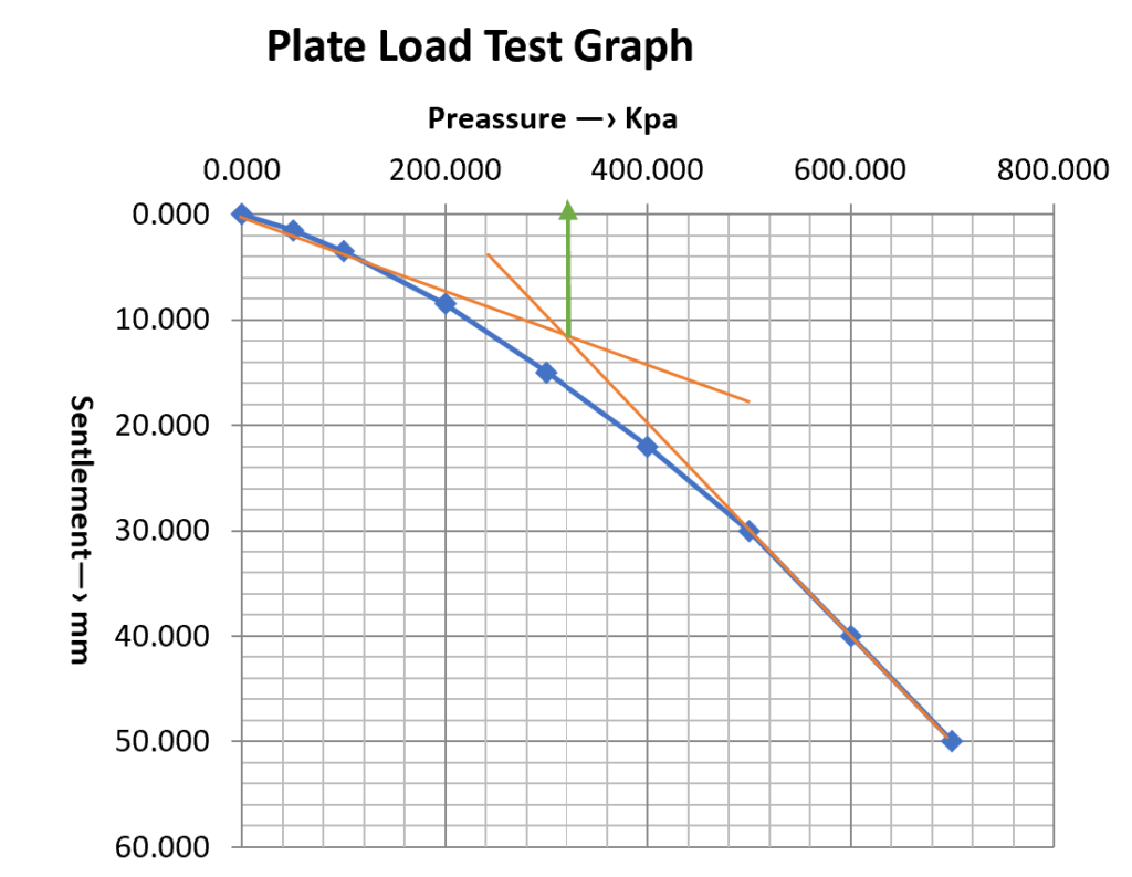
Thus, the failure stress or the ultimate bearing capacity of the soil from the plate load test is:
q_{ult,p}=320kN/m^2Ultimate Bearing Capacity
To determine the maximum load that can be supported on a square footing of 1.5m x 1.5m founded at a depth of 1.5m, we must first convert the ultimate bearing capacity obtained above assuming a foundation width of 1.5m. So that:
q_{ult,f}=q_{ult.p}\times \frac {1.8}{0.6 }=320\times3.0= 960kN/m^2Safe Bearing Capacity
The safe bearing capacity is then obtained by dividing the ultimate bearing capacity of the 1.8m x 1.8m foundation by the factor of safety.
q_{a}=\frac{q_{ult,f}}{f.o.s} =\frac{960}{2.5} = 384kN/m^2Therefore, the maximum allowable column load on the footing is given as the product of the safe bearing capacity and the area of the footing.
N=384\times1.8\times1.8 = 1244kN
To download the spreadsheet used to plot the settlement vs pressure graph, click on download link below.
Also See: Geotechnical Design of Spread Foundations to EC7
Sources & Citations
- Terzaghi, K., Peck, R. B., & Mesri, G. (1996). Soil Mechanics in Engineering Practice (3rd ed.). Wiley.
- Bowles, J. E. (1996). Foundation Analysis and Design (5th ed.). McGraw-Hill Education.
- BS 1377-9:1990 – Methods for test for soils for civil engineering purposes – In-situ tests. British Standard Institution