This article discusses moment resisting connections used in the design of single storey and multi-storey buildings. It highlights the common types of moment connections used and an overview of the design procedures based on Eurocode 3 (Part 1-8)
There are two broad ways of modelling steel connections with respect to stiffness and strength – as ‘simple’ or as a ‘moment resisting.’ Simple connections are typically considered to be nominally pinned, they are relatively less rigid and hence do not transmit bending moment. A steel frame’s connections can be designed as ‘simple’ as steel beams are not continuous, and the frame is braced in both directions. This ensures that the connections do not attract significant bending moment.
However, where the steel beams are designed as continuous or in the absence of bracings in a steel frame, the steel connections would attract significant bending moment, hence the connections must be designed as moment resisting connections. Comparatively to simple connections, moment connections are more expensive to fabricate. This is generally due to the much more required welding and local strengthening requirements.
This article discusses moment resisting connections used in the design of single storey and multi-storey buildings. It highlights the common types of moment connections used and an overview of the design procedures based on Eurocode 3 (Part 1-8).
Types of Moment Resisting Connections
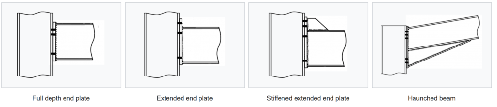
Both single-story portal frame structures and multi-story unbraced buildings often employ moment-resisting connections. The most common types of these connections found in multi-story frames are bolted, extended end plate connections, or full depth end plate connections. A hunched connection can be utilized when a deeper connection is needed to provide the bolts a bigger lever-arm. However, this circumstance is to be avoided at all costs, as more fabrication is bound to ensue.
In portal frame buildings, the eaves and apex of a frame are nearly usually connected with haunched moment-resistant connections since the haunch not only enhances connection resistances but also the resistance of the rafter.
Summarily, bolted end plate beam-to-column connections are the most often utilized moment-resisting connections; this can be seen (Figure 1).
An alternative to bolted moment resisting connections are the welded connections. However, while welded connections can offer full moment continuity, they are costly to make, particularly when produced on location1. In the fabrication workshop, bolted splice connections inside the beam span, at a place of reduced bending force, can be prepared for welded beam-to-column connections.
Other types of moment resisting connections would include:
- Splices in beams and columns, and apex connections in portal frames.
- Column Bases
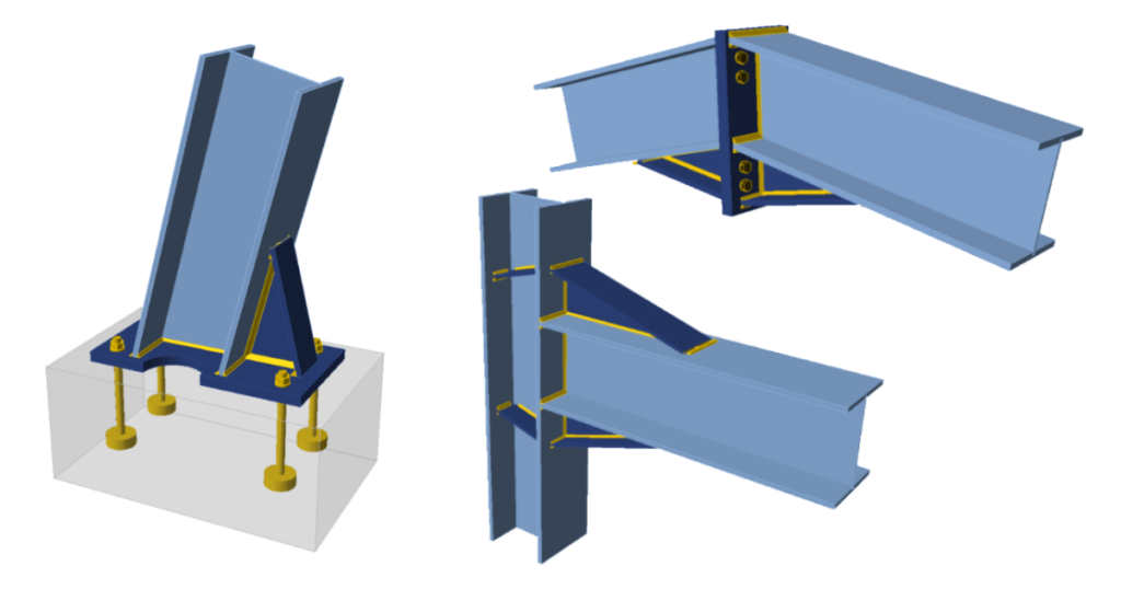
Bolted Beam-Column Connections
Unlike welded connections, bolted moment connections rely on high-strength bolts to transfer forces between the beam and column. The bolts pass through pre-drilled holes in the connected members and are tightened to achieve the desired level of connection stiffness.
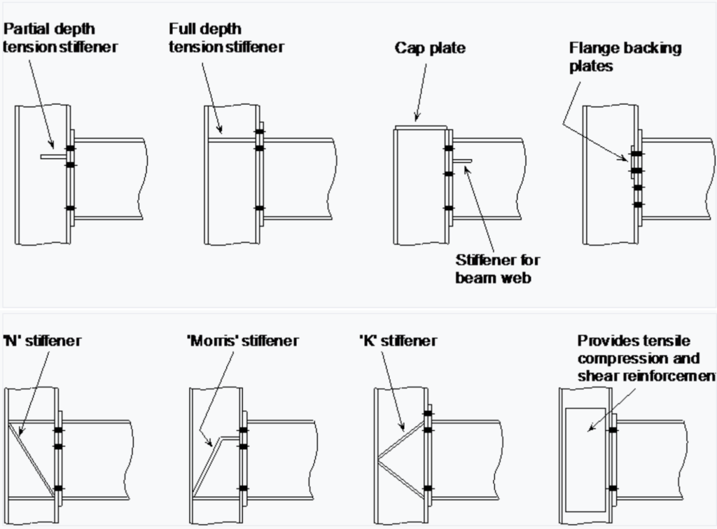
Bolted end plate connections between I- or H-section beams and columns can be modelled utilizing the methodology outlined in BS EN 1993-1-8. Sometimes additional stiffeners may be required to justify the strength of the connection. Prudent member selection during design, however, may frequently save this requirement. But occasionally, reinforcing one or more of the connecting zones is the only option. The figures below depict the variety of stiffeners that can be used (Figure 2).
Design Basis & Procedure
The design approach for bolted beam-column moment-resisting connections is based on Tension and compression forces in the bolts. The Tension forces in the bolts next to one flange and compression pressures in the bearing at the other flange work together to generate resistance in a bolted end plate connection. The total tension and compression forces are equal and opposing unless the beam has an axial force. Bolts in bearing and shear resist vertical shear; the force is typically believed to be resisted mostly by bolts next to the compression flange.
In designing a beam-column connection, a configuration of bolts and, if necessary, stiffeners are chosen; the resistance of that configuration is assessed; the configuration is then modified for greater resistance or greater economy, as appropriate; the revised configuration is re-evaluated, and so on, until a satisfactory solution is reached.
Below is the necessary iterative process involved in the full design process for an endplate connection.
Step 1
Calculate the effective tension resistances of the bolt rows. This involves calculating the resistance of the bolts, the end plate, the column flange, the beam web and the column web. The effective resistance for any row may be that for the row in isolation, or as part of a group of rows, or may be limited by a ‘triangular’ distribution from compression flange level.
The conclusion of this stage is a set of tension resistances, one value for each bolt row, and the summation of all bolt rows to give the total resistance of the tension zone.
Step 2
Calculate the resistances of the compression zone of the column web, taking account of the shear force in the column web, and of the beam flange.
Step 3
Calculate the shear resistance of the column web.
Step 4
If the total tension resistance exceeds the compression resistance, (Step 2) or column web shear resistance (Step 3), calculate reduced effective tension resistances for the bolt rows, where necessary to ensure equilibrium.
Step 4
Calculate the moment resistance. This is the summation of the products of bolt row force multiplied by its respective lever arm, calculated from the centre of compression.
Step 5
Calculate the shear resistance of the bolt rows. The resistance is taken as the sum of the full shear resistance of the bottom row (or rows) of bolts (which are not assumed to resist tension) and 28% of the shear resistance of the bolts in the tension zone (assuming, conservatively, that they are fully utilized in tension).
Step 6
Verify the adequacy of any stiffeners in the configuration.
Step 7
Verify the adequacy of the welds in the connection. (Note that welds sizes are not critical in the preceding Steps).
For a more detailed explanation of the above procedures, See: Joints in Steel Construction: Moment-Resisting Joints to Eurocode 3. (SCI – P398), SCI, 2013.
Welded Beam-Column Connections
Unlike bolted connections, welded moment connections involve the direct fusion of the beam and column materials. The welds join the members, creating a continuous and seamless path for the transmission of forces and moments. They offer high stiffness and strength, making them suitable for situations where precise control of deformation and resistance to lateral forces are essential. The continuous weld along the joint provides efficient load transfer capabilities.
The goal of any welded connection is to be able to guarantee that the primary stiff joints, or full-strength joints, between beams and columns are created in a factory setting. This ensures that short stubs of the beam section are welded to the columns while maintaining component sizes small enough for shipping.
Design Basis & Procedure
If a frame is statically determinate, a partial strength connection is adequate to resist the design moment. However, if the frame is statically indeterminate, as would be the case of most unbraced frames, requiring moment connections, the connections must have sufficient ductility to accommodate any error in the design moment that may result from support settling or frame flaws. Thus, welded connections welds must be made to full strength in order to do this.
The resistance of a welded beam to column connections is summarized in the following five steps:
Step 1
Calculate the design forces in the tension and compression flanges of the beam. The presence of the web may be neglected when determining these forces.
Step 2
Calculate the resistances in the tension zone and verify their adequacy. If, for an unstiffened column, the resistances are inadequate, determine the resistance for a stiffened column and verify its adequacy. Column flange stiffeners will normally be required.
Step 3
Calculate the resistances in the compression zone and verify their adequacy. If, for an unstiffened column, the resistances are inadequate, determine the resistance for a stiffened column and verify its adequacy.
Step 4
Verify the adequacy of the column web panel in shear. If the unstiffened panel is inadequate, it may be stiffened, as for an end-plate connection.
Step 5
Verify the adequacy of the welds to the flanges and.
For a more detailed explanation of the above procedures, See: Joints in Steel Construction: Moment-Resisting Joints to Eurocode 3. (SCI – P398), SCI, 2013.
Also See: Designing a Moment Resisting Column Base Plate
Sources & Citations
- BS EN 1993-1-8: 2005 Eurocode 3: Design of Steel Structures. Part 1-8: Design of Joints, BSI 2010.
- NA to BS EN 1993-1-8: 2005 U.K National Annex to Eurocode 3 Design of Steel Structures. Part 1-8: Design of Joints, BSI 2008.
- Joints in Steel Construction: Moment-Resisting Joints to Eurocode 3. (SCI – P398), SCI, 2013.