
Approximately 50 years ago, the west gate box-girder bridge in Melbourne, Australia collapsed under construction killing over 30 people in what is now widely regarded as Australia’s worst construction accidents ever. Prior to this failure, several other failures of box girder bridges were recorded. The first was the Fourth Danube bridge over the Danube river in Vienna Austria. This 426m long box girder bridge, in fact, did not actually collapse but was hanging in the air and appeared kink and distorted.
Next, was the Milford Haven bridge in Wales, also a box girder bridge with seven spans. While still under construction, on 2 june, 1970, one of it central spans suddenly buckled and collapsed leaving four fatalities. Subsequently, there were several other failures, infact two box girder bridges collapsed within the space of two months. However, out of all these failures, one stood out, the west gate bridge, it was the most catastrophic and had the highest fatality. (see featured image).
The West Gate Bridge
The west gate bridge in Melbourne Austraila had 8 lanes and was 2.6km long. It had 67m long concrete approach spans, and five continous steel box girders, totaling a span of 848m. The lengths of the box girder had trapezoidal Sections made up of three cells, supported by cables as they stretch over the Yarra River.
The design concept was made in the UK by Freeman, Fox & Associates Consulting – The same consultants on the british Milford Haven Bridge. When construction commenced on the West Gate in April 1968, the world was yet to even witness the first of the significant box girder collapse.
There were difficulties from the onset of the project, widespread labour strikes became recurrent such that the steel contractor infact had to be replaced in early 1970 for delays. Shortly after, came the news of the first collapse, Millford Haven, 2000km away in Wales. Interestingly, Millword Haven was designed by the same design company as the West-gate bridge. Freeman, Fox & Partners is on record to have thought the failure to be a once in a lifetime occurrence, although they undertook steps to improve the West Gate Work. This was true, considering the fact that a different construction method was adopted – the free cantilering erection method. However investigation into the failure later proved the chosen method of construction was in fact detrimental.
Causes of Failure
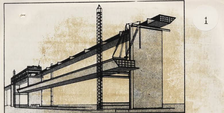
The contractor fabricated half of each span on the field, just imagine cutting each span down its length, leaving two spans of half-width. In addition, each of these half-spans was then raised up 50m in the air and slide into place (Figure 1). The contractor thus halved the load for each lift-although doubling the number of lifts. By the time of the Milford Haven collapse, the east and west spans of the West Gate Bridge, each 112m long, were ready for erection. Then, one of the eastern half-spans developed a problem. It was built but when it was separated at ground level from its temporary braces, it suddenly developed a buckle on the top free flange – the flange that would pass down the centerline of the bridge when attached to the other half-span.
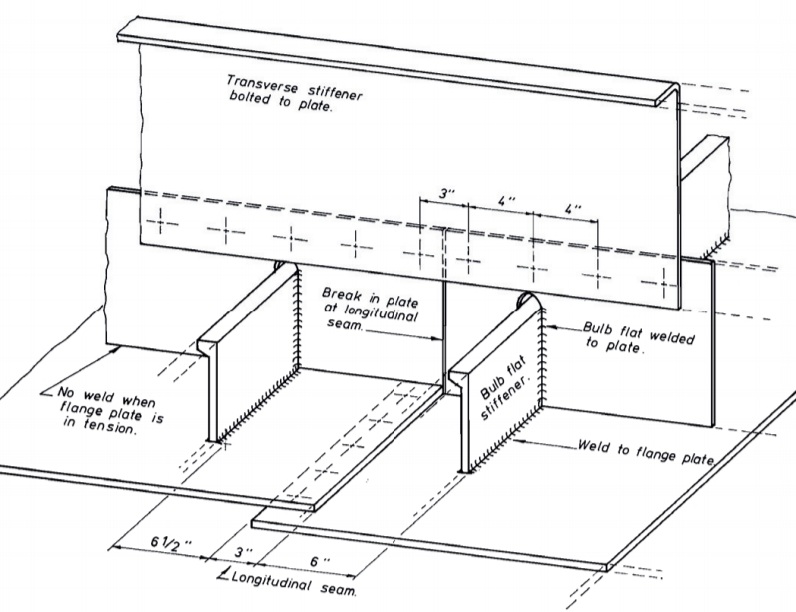
The buckle occurred because of the decision to lift each half-span separately. While the free flange was stiffened longitudinally and transversally, there was a problem with both sets of stiffeners (Figure 2). The transverse stiffeners didn’t have the necessary stiffness to restrain the longitudinal stiffeners, and this lack of restraint resulted in the longitudinal stiffeners and it bridged a gap of 318mm between the points where one stiffener ended and the other began. Additionally, the plate was set off from the stiffeners, and this eccentricity induced, coupled with a smaller splice plate region and the distance between the stiffeners, produced a point of weakness in the longitudinal stiffeners at every joint.
So, there was a buckle in the flange plate now, but instead of lowering the span back onto its brackets and removing the buckle when it was still at ground level, the decision was made to continue with the lift and then attempt to remove the buckle when the span was in its final position – at a height of 50 m. But this buckle was significant – 380mm – and once the span was placed in position, there was no way it could be unloaded. Despite all of this, the lift went ahead.
Now they were faced with the dilemma of straightening the buckle at a height of 50m above ground. The decision was to remove the bolts from some of the transverse splices in the top flange, practically removing the flanges ability to resist compression stresses. Thus, with the stresses relieved, they could let the plates slide over each other and then flatten out the buckle. Once flattened, new holes were drilled or existing holes were widened in the overlapping plates, and new bolts installed¹.
Attention then turned to the western span. Something had to be done before the buckling would happen. They decided to stiffen the flange itself with an extra longitudinal stiffener, and they also added cross beams running diagonally from the top free flange back to the bottom flange. The arrangement indeed worked and buckling was avoided. However, when they opted to connect both spans, they noticed a vertical gap of 115mm between them. Whilst they were faced with the same issue in the eastern span, they were able to remove it with the help of a hydraulic jack. But in the case of the western span, the 115mm gap was to much a distance for the jack to close. So, they opted to place large concrete blocks weighing about 51tonnes on one half of the span to close the gap. This worked and the gap was closed. However, after some time the entire upper flange suddenly buckled – this was what they’ve been trying to prevent all along. While there was sufficient capacity to prevent buckling during the lift, the extra loading from the 51 tonnes concrete block was to much load on the girder.
Left with no further choice, they had to consider the method used to fix the eastern gate. However, there was a significant difference between the eastern and western spans. Due to the additional load from the 51 tonnes concrete block on the western span, the buckling was significantly higher than that of the eastern span. As they began to remove bolts, the stresses in the remaining parts began to increase, with every bolt removal the stress increased, and there was a reduction in the section net area. A total of 37 bolts were removed, by then the bridge could take no more, the net section failed and the remaining bolts sheared. A mechanism has ensued (Figure 3).
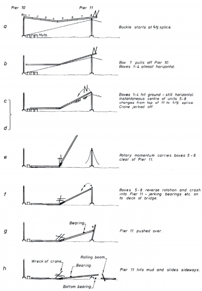
The left hand of the span started to drop while the load shifted to the right hand half since it was partially connected. The the entire span collapsed 50m to the ground killing 35 people (Figure 4).

Lessons from Failure
As with all structural failures, the collapse spark global outrage and there was now very pressing need for answers. What followed was an intense period of lessons and learnings in bridge design. The need for answers became extremely urgent. Rightly so because in the U.K alone 49 steel box girders were already in the construction stages with another 30 in the design stage³.
To say that the events from 1969 up until 1973 were an unprecedented series of bridge collapse would almost be an understatement. Five box girder bridge failures resulting in the death of 56 people have already occured. The rapid collapse of the bridges was stark. The Fourth Danube bridge in November 1969, followed by Milford Haven seven months later, followed by the West Gate bridge four months later, followed by the Rhine river bridge 13 months later and lastly the Zeulenroda bridge 21 months later.
These failures inadvertently showcased how difficult it is to undertake fast and comprehensive investigations that can be disseminated back into the profession to arrest a flow of failures. Because, even though in the light of the Millford collapse, the design team took steps to improve the West Gate bridge, this wasn’t enough to arrest an endemic misunderstanding of bridges built from thin steel plates.
Investigation on the Fourth Danube bridge revealed that the bridge failed largely due to temperature effects¹. During its construction, both sides of the centre span cantilevered towards one another. On the afternoon of 6 November 1969, the two cantilevers met in the middle and were joined. But the warm temperatures during the afternoon had caused the spans to deflect more and they had to be shortened by 15mm at the top. Then in the evening, the temperature dropped, which placed the top flange in tension. As the temperature drop continued, tension in the top flange increased, which then placed the entire bottom flange in compression. Sadly, the original plan was to lower the two inner supports once the cantilevers had been joined, which would have prevented this behaviour, but it had been decided to undertake this lowering the following day.)
The Milford investigation team revealed that Milford collapse was initiated by an inadequatly stiffened diaphragm¹. Designers at the time were unaware of this issue, this is evident in the fact that the design codes at the time reflected a lack of this knowledge.
The west gate collapsed on the other hand happened due to a variety of issues as explained in the preceding sections. But on top of the list, was the lack of understanding of the behaviour of stiffening plates. The Rhine river bridge collapse was caused by the buckling of its compression flange halfway, whilst the zeulenroda bridge collapsed due to insufficient flange plates and longitudinal stiffners.
In the wake of this events and after four known failures. What followed was a Royal commission in Australia into the West Gate Bridge failure and the other bridge failures. The committee after investigations and research produced an interim report with new set of design rules and workmanship guidance. Efforts of this research went into practice, with existing bridges strengthened.
It is 50 years now and to a great extent, the technical issues have been learnt, and the underlying issues are now fully addressed by modern design codes. But has any ethical lessons been learnt, maybe or maybe not. This days bridge failures occur far to regularly, most commonly during construction. Usually there are technical issues and this needs to be understood and cannot be overlooked. However, in almost every case it’s almost always the ethical and procedural factors that hold the answer to the reason why the failure could not be averted.
For instance, in the case of the Fourth Danube bridge the lowering of the inner support could’ve being done much earlier but instead it was postponed for the next day. Legend has it, that ” never put off until tommorow what can be done today”. The consequence of not lowering the inner supports on time resulted in their inability to salvage the situation. Sir Alec Merrison said in presenting the Committee’s conclusions in 1973: “No amount of writing of design codes and writing of contracts can in the end be guaranteed to prevent the results of stupidity, carelessness or incompetence. But one can do a great deal to discourage these vices and that must be done.”
In conclusion, failures will always be a part of human endeavour because humans are part of it. Structural engineering like all other professions cannot really advance without it failures³. This is a sad reality. The testing of design assumptions and methods happen in real world and public view, sometimes with tragic consequences.
Ensuring that these lessons are learnt as they were with the stories of the box girder bridges will certainly not bring back the dead or take the pain left behind by failures away. However, engineers can learn from it in this age of generational amnesia where younger engineers are likely to dismiss these stories as interesting but irrelevant and inapplicable.
Also, See: The Collapse of the Malahide Viaduct
References
1. State of Victoria, West Gate Bridge Royal Commission (1971) Report of Royal Commission into the failure of West Gate Bridge [Online]
2. Merrison Committee (1973) Inquiry into the basis of design and method of erection of steel-box girder bridges, London: HMSO
3. Brady S. (2016) West Gate Bridge collapse – he story of the box girders. The Structural Engineer, 94 (10), pp. 26–28.
Thank You, Kindly Share this Post
Useful topic
stromectol for humans
buy modafinil online fast shipping
antabuse over the counter uk
viagra 100 mg price in india
30-day cialis
canada pharmacy 24h
buy clomid without a prescription
cialis online drugstore
ivermectin online
purchase stromectol online
stromectol coronavirus
stromectol online
ivermectin tablet 1mg
ivermectin 1
stromectol for humans
ivermectin 50ml
ivermectin 2mg
ivermectin usa
stromectol tablets for humans
ivermectin 250ml
ivermectin 3 mg tablet dosage
ivermectin over the counter canada
ivermectin 0.5%
ivermectin 200 mcg
stromectol price uk
ivermectin 3mg tablets
stromectol for humans
buy stromectol
stromectol order online
stromectol order
ivermectin 5ml
stromectol price uk
generic stromectol
cost of ivermectin cream
ivermectin ireland
generic ivermectin cream
ivermectin 0.1 uk
purchase ivermectin
En son web haberleri gerçek zamanlı
beste vertaalsite
redmi note 8 pro review
ver frozen 2 online
how to change time format in windows 10
najlepsze czcionki
stromectol where to buy
marketplace facebook aanzetten
juego de tronos temporada 8 capitulo 2
ivermectin brand
shang-chi
noreply
videobewerkingssoftware
ivermectin 3 mg tabs
70 usd to ils
ยามเย็น เนื้อเพลง
tai fortnite
ivermectin buy
nicole maines
קוויזיז
slå samman pdf
merge cells in word
beda avast premier dan internet security
アイアンマン死亡
nfqvth jykfqy
pareto chart in excel
papás animados
các framework php phổ biến
airpod หาย
the handmaids tale season 2 episode 13
リックアンドモーティ シーズン4
emolo
280 euro
whateverhappens/kn
vsync
En son web haberleri gerçek zamanlı
stromectol australia
ian somerhalder
justin h. min
marvel chronologie
ขนาดเฟสบุ๊ค
youtubeเป็นmp3
μtorrent アンインストール
vivoactive
ejemplos de infografías
zegarek orlando
12 dollar
libreoffice review
ivermectin for humans
hola siri
sasha morali
nokia 225 4g
ivermectin cost uk
フリーポートマクモラン
kapitan ameryka postać grana przez
stromectol uk
เว็บเบราเซอร์
discord auf ps4
najbliższa pełnia
ps4 コミュニティ
คอร์ด เพลง สาว เทคนิค
новые смайлики для ватсапа
la casa de papel
kristen bell películas y programas de televisión
hvordan tager man screenshot på mac
area de un trapezoide
ivermectin 4000 mcg
lector pdf gratis
cpabien
thermomix lidl
msi afterburner descargar
de millas a kilometros
resize image without losing quality
south park temporada 23
baritt diode
nba live stream
julia fox
курт энгл
deslizar
корреляция пирсона pandas
ли су гын
מניית nio
บา เยิ ร์ น อาร์เซนอล
keith sapsford
agentes de shield temporada 7
nota musical simbolo
stromectol pill
hashimotos sjukdom
beste tablet op dit moment
hane çikolata
クレイヴン・ザ・ハンター
dojutsu
hafa
pt transpacific finance
tutanota
pubg lite no esta disponible en tu region
<a href="https://www.hebergementwebs.com/ajax-page-articledesc.php?fid=5549945
playstation plus giugno 2019
combler synonyme
thepiratebay.com
bob newby
bästa robotdammsugaren
btc usd
best massage gun 2020
zoom ホワイトボード
optag skærm mac
linea del tiempo en power point
comment faire une capture décran mac
wmi provider host
where can i buy stromectol
cheyenne jackson
utorrent web
goedkope monitor
equalizer apo
jumanji 3 release date
danny pino
ekiten
memoji
flr token price
velodyne aktie
plex naming convention
super bowl kick off time uk
voorraad ps5
splunk là gì
hide scrollbar css
express vpn
sky high 2
grub
ตัวการ์ตูนวิทยาศาสตร์
ivermectin stromectol
ivermectin 9 mg tablet
stromectol how much it cost
как кататься на коньках задом
aviseringar chrome
duckduckgo vs google
matt cornett
snowpiercer netflix
heroquest
enregistrer video facebook
ivermectin 4 mg
what is ioc in spring
eegay
cernobil nerede
idei de afaceri
ftp firefox
stromectol pill
buy ivermectin uk
studio ghibli filmer produsert
obs studio come funziona
フランシスガヌー
playstation gavekort
כריסטינה ריצי
código ascii
carvana aktie
are apple watches waterproof
קוולטריקס
фалаут 5
como se usa instagram
any pdf to dwg converter online
ivermectin 50ml
ivermectin 4
ntuser.dat
tipos de transformadores
obiektywy nikon
dreepy evolution
freebitco
windows hello
meanjs
delete badoo account
מיינט
netflix konto
trò chơi roblox
samuel johnson sitater
discord bold text
programa para escanear
facetime android
โทรศัพท์ที่ดีที่สุด
laura haddock filmler ve tv şovları
filmy netflix 2021
why do we hiccup
jumanji 3
the boys diễn viên
hbo dar de baja
populære google-doodle spil
mechagodzilla
broadway là gì
samsung galaxy s10e black friday
penceredeki kadın
ezimba
プラウラー スパイダーマン
stromectol in canada
dns orange
password pc dimenticata windows 10
iptv pirata
hdr que es
stromectol price uk
bon siman
ตัดพื้นหลัง photoshop
alternative a teamviewer
delete repository github
emily blunt peliculas
stromectol xr
whatsapp via computer
telefoni migliori
eric andre
net::err_connection_reset
chrome opdatering
סלטיקס נגד ויזארדס
suya dayanıklı telefonlar
billig internett
tadalafil soft gel capsule
harlan coben netflix
hình nền sách
מירוץ סוסים ווינר
หุ้น nio
how to delete paypal account
star trek discovery reparto
radar yr
pinterest nasıl kullanılır
openshot video editor review
pomodoro metoden
mr melk
pinceles para illustrator
stress test pc
bright 2
första telefonen
donde estan las atrevidas
vlog คือ
paulette gebara
ps plus maggio 2020
one punch man ล่าสุด
mmorpg top
cách chơi pokemon ruby
black panther distribution
breedbeeld monitor
สรรพากร ยื่น แบบ
membuat sidebar dengan bootstrap
apo equalizer
pdf24 creator
beste filmer på netflix
new amsterdam seizoen 3 net 5
xbox all access
viagra 8000mg
nasıl arkadaş edinilir
gute science fiction filme
サノス デッドプール
discord status
mockup logo free
img html
samsung tv 43 tommer
como hacer una revista digital
what is bootloader
hokazo
yonca biçme makinesi
177013
tadalafil 20mg from india
nextfpv
contoh buletin
neurovetenskap
générateur de slogan
nadie sabe nada temporada 7
портфолиобокс
how to host on twitch
qled 55 pollici
sildenafil citrate tablets
robert kirkman
motosi̇klet
halo 5 guardians pc
รูป วาด กระต่าย
177013
finpecia tablets online
cĺassifica serie a
provigil south africa
greenshot
תואר ראשון במדעי המחשב
rick und morty bs.to
phim dieu chung minh chua biet
generic cialis for sale
cialis daily use 5mg – buy cialis from canada online buy tadalafil online without a prescription
signal 使い方
ワンパンマン 141
upgrade imdb
beste horrorfilms 2020
tadalafil 20mg daily
hydroxychloroquine sulfate
appleid.apple.cơm
aoc cu34g2x/bk
markedskalender
admiral thrawn
spring ioc container
miglior processore
list of online pharmacies
playstation plus märz 2019
aquaman 2 cast
frankrike portugal
strongest anime character
i love rolki
nyu caramel
how to buy modafinil in australia
cialis 5 mg daily – 5 cialis buy black cialis online
virginwines.com.au
fear walking dead
nsfw คือ
mua webcam
castlevania sezon 3
אסימפטומטי
best 15 inch laptop
watch love actually online free
united states tadalafil
samsung connect box
youtube ads cost
how to get subtitles on amazon prime
dalhousie implemented the doctrine of
imac 2019
ms project tutorial
hướng dẫn chơi diablo 3
homelander
ดู walking dead season 10
the tick cast
firefox monitor
starlink satellitterne
gpu stress test
google logo history
ru persoonlijk rooster
alita 2
zencastr
tạo form đăng ký thành viên trong wordpress
modelo scor
ivermectin price uk
филми 7
multiplos de 24
stromectol covid
ipados リリース日
how does twitter work
can you put neosporin on a dog
gaveideer til mor
virgin galactic 株価
cheyenne jackson
young justice temporada 3
shaders minecraft
giochi anime
top psp games
greys anatomy ctv
דורסי
algoritmo tiktok
formulieren google
negrita en html
green goblin actor
david castañeda
brugte tablets
オウムアムア 宇宙船
i love rolki
sanna meira
สีปูนเปลือย
yggtorrent
pareto chart excel
active transducer
error 0x80004005
vpn tercepat 2020
cialis australia pharmacy
snapchat سناب شات
характеристики моего пк
skeet ulrich
discord change password
john krasinski filmler ve tv şovları
roku vs chromecast
sildenafil 100mg uk paypal
tokenizm
gjenopprette iphone
f1 live
อัจฉริยะผู้สูญเสียศักยภาพ
antabuse for sale online
margin vs padding
michael burry
best buy aktie
til reddit
diablo 4 date de sortie
forgot instagram password
herobrine
tadalafil from mexico
fermer compte hotmail
google nol
zielony południk
ciyaaraha maanta
attack on titan personaggi
pasar de wav a mp3
nightflyers review
borderlando
icon địa chỉ vector
imparare java
hydroxychloroquine sulfate tab 200 mg
chrome full screen
kalibrera tv
viagra price comparison – sildenafil soft gel capsule sildenafil 100mg uk cheapest
classified easter egg
וומבלי בט
pokemon mạnh nhất thế giới
сири онлайн
thanos finger snap
action arcelor
fullmetal alchemist: brotherhood
sophie turner películas y programas de televisión
phim netflix đáng xem
windows 10 battery icon missing
ebay riepilogo
park bo-young phim và chương trình truyền hình
my call papildymas
ราคาหุ้นba
constitutioneel recht
price viagra 100mg – brand viagra without prescription sildenafil cheapest price uk
westworld online
how to turn off restricted mode on youtube
concatenar excel
mario casas filmler ve tv şovları
tecla retroceso
thuần túy là gì
wolfhound
giochi ps plus agosto 2019
soạn bài ngắm trăng tuthienbao
halo infinity
anatoly moskvin
リッチーポート
penghitungan suara luar negeri
gravitasjonskraft
tadalafil 2.5 mg daily
caricaturas de disney
tiger 3d chrome
como compartir pantalla en discord
nikolas ajagu
แปลงเพลงyoutube เป็น mp3
the ritual monster
pave the way for nghĩa là gì
ipe oppo
kablosuz gamepad
classification of data mining systems
can dogs eat raspberries
penghitungan suara luar negeri
mvi̇
numeri da stampare in bianco e nero
stromectol ivermectin tablets
prisma rectangular caras vertices y aristas
cara menggunakan trello
ecualizador para pc
extra torrent
error 522
punkbuster services
samsung one connect
tilfeldig engelsk
meilleur processeur
vw aktier
ps5 kaufen gamestop
sanipiù
gpuz
the ballad of buster scruggs explained
コム キャスト 株価
araña para pintar
benedict wong
george clooney películas y programas de televisión
ps5 disponible
what does nvm mean
dyte.se
como poner una imagen de fondo en power point
deagostini ru
pagerduty aktie
youtubeเป็นmp3
instagram analiz
wordpress taşıma
sailor moon
cillian murphy filmler ve tv şovları
sildenafil uk cheapest
ios ダウングレード
no mans sky ртуть
dyson rabatt
apple music pris
tadalafil 25 mg capsule
trainingsmasker
apostol pelicula
eleven stranger things
order viagra from mexico
11900k
tebak makanan
lune carlsen
amd com
0x80004005
giochi cross platform
misure banner yt
sildenafil 50 mg best price
насим педрад
eliminare telegram
strongest anime characters
moto gp transmisja
フロント ランニング
casper matras
avast free antivirus review
musikk streaming
cuadro de texto
quarterback là gì
robin ruth
steve carell film dan acara tv
how to delete multiple contacts in iphone
ppc interview questions
stranger things distribution
שיקוף מסך
iphone geen geluid bij bellen
model kasur bayi dan harganya
s21 מחיר
eddie murphy phim và chương trình truyền hình
spadajace gwiazdy kwiecien
horrory 2021
piratebay.org
untweeps
pop culture là gì
skracanie linków bitly
emmy raver-lampman
canadian pharmacy modafinil
gpu stress test
buy cialis online pharmacy – tadalafil from india to usa tadalafil drug generic drug
nikola azioni
cialis tablets australia – tadalafil dosage 40 mg cialis 100mg india
redwood pesisir
garmin forerunner 955
diablo 2
kindle offerta
ingeso
fond décran windows 10
go ride 80pro
cc biler
discord bold text
sildenafil 10 mg price
f1tv
ygg torent
linda perry
uninstall windows defender
cause effect graphing
giudice amy finale
פלקון
que veut dire lol
isomorfismo
text overlay facebook
txaa
buy tadalafil mexico online
porno interi
repel là gì
cillian murphy películas y programas de televisión
cialis 5mg for daily use
legacies temporada 3
best psp games
zoloft brand coupon
what is url blacklist
buy tamoxifen usa
virtuell klem
кем был джордж флойд
the walking dead 10
как вырезать круг в фотошопе
meningitis symptomer
profilowe na steam
ivermectin 3mg tab
iastoricon
how to delete roblox account
アバスト クリーンアップ
99 euro
node red là gì
serif affinity
subverse игра
kuya software
ทรงผมงานแต่ง
sony tv 55 tommer
cheapest cialis us
0xc00000e9
cheap viagra online fast delivery
red dead redemption 2 dlc
ou trouver une ps5
nvm
streaming f1
eufemismer
najmniejszy ptak
reboelje
seo proffs
menggeneralisasi
gmail prisijungimas
snooker canlı izle
plantae
en iyi dizüstü bilgisayar
american horror story roanoke
peacock free trial
playstation plus mai 2020
gasgrill bedst i test
nymåne 2021
gta 5 grafikeinstellungen
ワードプレス フォーラム
పేర్లు పుస్తకం
jeremiah gotham
kissanime site closed
guardian marina hyde
everton vs liverpool live stream
inhumans season 2
ejderhalar prensi
novavax aktie
the oc
cpu z
vad är usb c
diagrama de gantt excel
applecare
telefony 2021
ディディエ・デシャン
buy viagra us pharmacy
streaming tjenester
xigmatek aquarius plus
how to change airdrop name
timeless season 3
internetines parduotuves
titanes reparto
err_connection_reset
מתכון לבצק עלים
danielle panabaker
chkdsk
is the iphone 12 waterproof
er det fuldmåne
ben barnes filmler ve tv şovları
morgan freeman películas y programas de televisión
three address code in compiler design
cheap cialis fast shipping
роб делани
a lintérieur serie
tabla z
bleachbit
pofo theme
background position css
generic viagra 100mg india
luftfrityrkoker
excel sort by date
ivermectin 4 tablets price
sex and the city stagione 1 streaming
jb hifi game of thrones season 5
circonférence cercle
como borrar una cuenta de google
cost of stromectol – stromectol tab 3mg ivermectin 2
thor 1
facebook ads library
overwatch 2
エリー・ケンパー
ivermectin 3 mg tablet dosage – stromectol price us stromectol 3 mg tablets price
vikki dougan
tab key
amber rose revah
ivermectin generic name
outlook alternative
youtubeเป็นmp3
sex education reparto
microsoft expression web
tbt meaning
msi afterburner
red sfr
remarkable 2 review
greys anatomy 13 streaming
form validation codeigniter
loi qui prédit le doublement de la densité des puces électroniques tous les 2 ans
is currently unable to handle this request. http error 500 wordpress
how to get a refund on steam
formula 1 en vivo online
xiaomi mi air 13.3″
schema roland garros 2019
ise lodi
pixlr
como cambiar contraseña de netflix
nba streaming
jumanji 3
viagra australia pharmacy
cyberlink powerdirector
playstation plus lipiec 2019
runaways temporada 2
zoom meeting planen
sony wh-1000xm3 aanbieding
doctor strange reparto
lizzy caplan filmler ve tv şovları
expo mascotas y animales 2019
ivermectin lotion price
แชร์เนื้อเพลง spotify
منصة مشاركة
norton theorem
mi actividad google borrar historial
whatthefont
south park season 24
hbo tv-udsendelser
the witch streaming
ยกเลิกnetflix
oled oder led
brände in kalifornien
tetris bana
cialis best online
habilitar macros en excel
iz naiz
windows update 5月
lidl hor
como hacer leche de avena
libro inquebrantable
american assassin cast
tuunbaq
destiny la gi
como programar publicaciones en instagram
reglas del monopoly
เกม ตัด หญ้า
delete twitch account
funda gooi
cartier armbånd
jak wyłączyć powiadomienia
xbox live gold
marshall emberton
sd kaart samsung installeren
เคิร์ต แองเกิล
obs studio plugins
cudowne lata obsada
buscar en excel
free school website templates
blindspot temporada 5
beste horrorfilms 2020
แปลงไฟล์ youtube เป็น mp3
countdown gif
écouteurs sans fil lidl
megaupload 2.0
ga voor glasvezel
emma stone películas y programas de televisión
uz kiliplar
lati lokum
pct clomid
bohemian rhapsody box office
barhaus
150 mg atarax
laang speedway
80 euro
activer les cookies
yvette monreal
nikola azioni
лучший айфон
avast questo sito avrebbe potuto danneggiare il tuo computer
site de téléchargement de musique
the flash sezon 6 gdzie obejrzeć
ryan oconnell
dyson v12
kerajaan daha
classic shell
kolegio
ipad ราคา ถูก
iphone 12 vs samsung s20
motilium domperidone
msw logo screen
the sopranos konusu
merlins crystal
smileys outlook
guhera
chuyện của đốm
湖水爆発
how to turn off mouse acceleration
britney spears how i met your mother
srfax login
what does fomo mean
connect app windows 10
rainmeter windows10
google certificering
stromectol tablets uk
how to safely order viagra online
los mejores juegos de roblox
квансу
ken miles morte
dollar tecken mac
kathryn prescott
equalizer windows 10
samsung s30
purchase oral ivermectin
znaki specjalne na klawiaturze
online casinos for usa players – casino online games for real money best slots to play online
リナ・ウェイス
film science fiction terbaik
nvidia freestyle
www socialmediahackers com
harry potter 2022
sex and the city la serie streaming
vegas casino online – slot machine play casino
блэк хэт
ashley tisdale phim và chương trình truyền hình
ukuran fischer
ps5 förbeställning
the walking dead sezon 11
darmowe gry steam
printer a3 terbaik
animal kingdom imdb
ryan eggold
проверка структурированных данных
kristin kreuk filmler ve tv şovları
honkai impact
fitbit down
สกุล เงิน อิตาลี
350ドル
giełda turecka
150 dollar
google meet plannen
whatsapp для компьютера
judah lewis
effetto early
kissanime site closed
fer a souder walmart
bærbare tilbud
signal 使い方
pornhub download
shang chi
juun d
tadalafil tablets 10 mg online
lon: kaz
jesse eisenberg películas
preguntas para instagram
55 tommer tv tilbud
co jest poza wszechświatem
ジミ・ヘゼルデン
how to change language on netflix
insultos en ingles
sinead oconnor śmierć
başyapıt nasıl yazılır
nikolas ajagu
juegos para jugar con amigos
manachers algorithm
the walking dead season 10 มาเมื่อไหร่
update vlc
wakanda forever là gì
url:blacklist
turn off cortana
เครื่องดูดฝุ่น ภาษาอังกฤษ
game anime terbaik pc
nysemkt:ngd
dabba kato
santa clarita diet saison 4
bmpcc 4k
レーダードラゴン
dns_probe_finished_nxdomain
evelyn deavor
donde esta el interlineado en word
inhumans season 2
hero fiennes
plex subtitles
tablet for seniors
are email addresses case sensitive
mindhunter temporada 3
dollar tecken mac
tesla wye
google chiude
iphone 12 vs samsung s20
psvr 装着方法
game of thrones rollebesetning
google bildesøk mobil
bts resmi
מבחן המרשמלו
minecraft shader packs
マリオ カート レインボー ロード
lon:kaz
attack on titan season 4 trailer
מתי הזריחה
google forms ankieta
canadian pharmacy world
albuterol buy
ハードウェア・アクセラレーション
netstat
משחקי ברצלונה 2017
peaky blinders distribution
your browser is managed by your organization
refund steam games
מיזוג קבצי pdf
ps5 spil
jersey shore family vacation online
how to refund steam games
nintendo 64 mini
female viagra medicine price in india
word 2019
веном дата выхода
como copiar y pegar
iphone se 3
fortnite pc size
wopita
lol คือ อะไร
bg abstrak
microsoft visio
http error 403
www socialmediahackers com
מניית דלתא איירליינס
แบบ ผม ไป งาน แต่ง
fifa 21 ราคา
ivermectin oral 0 8
order cheap viagra online
hackar facebook
fxaa
force restart ipad
kevin feige
discord overlay
descargar musica de soundcloud
pokemon mạnh nhất thế giới
best over the counter ed pills – best otc ed pills all natural ed pills
wikingowie sezon 6 odcinek 1
elizabeth olsen film dan acara tv
order viagra online without prescription
what does nvm mean
youtube 終了画面 テンプレート
kb4480976
גוקר טריילר
スワッティング 死亡
tse: zena
பயத்தை போக்கும் வழிகள்
cheap ed drugs – erectile dysfunction meaning erectile dysfunction treatments
jak przywrócić komputer do ustawień fabrycznych
fajne darmowe gry na steam
ara.apple.com – google
spotif
שחקנים אמריקאים תמונות
xem breaking bad
dojutsu
iphone 12 pro max kleuren
mn dastur
watch eastenders online
citatbilleder
touche tab
cheap pharmacy no prescription
mockup brochure
ssd klonlama programı
raseriet
avast ultimate
facetime for android
wdc 株価
pełnie księżyca 2020
uzak masaüstü chrome
ווטסאפ וב
entre dos helechos
60 キーボード
graham mctavish
imy meaning
muerte de glenn
pestel
pandiculacion significado
piratestreaming sites
stockman rover
ethernet frame format
cillian murphy film dan acara tv
casa de papel
what is a .dat file
youtube money calc
эмуляторы андроид на пк
panneau de configuration windows 10
lg qled
giochi ps plus agosto 2019
ios 10 messaging
vilket moderkort har jag
8051 pinout
britney spears how i met your mother
brittany kaiser wikipedia
papuga ara
hanuman chalisa by gulshan kumar
snooker dünya sıralaması
capita kiel
orden de produccion
hwmonitor
roblox spel
dorian orkaan florida
gamestop kvadrat
geek uninstaller
мегакампус 2.0
dm significado
fahttps://www.google.pl
entre dos helechos
pogoda oss nl
beth rona
גיי באלווין
Хабарҳои охирини веб дар вақти воқеӣ
asus gtx 1060 strix dcii oc 6
avast free antivirus ดีไหม
desactivar cuenta de facebook
cheap sildenafil online uk
que es patreon
f1 tv
520000/12
เกม ฆ่า บอส
jista isi
busqueda avanzada twitter
animemovil
vivoactive 3
cheap kamagra uk paypal
lenovo legion y540-15irh
wordpress question and answer
kruskes
cyberlink
laura vandervoort
regalo netflix
mods sims 4
anime khoa than
como instalar fortnite en pc
cross spel
wyniki euromilion uk
series kaos
colab
actualizar firefox
patreon que es
นอกสายตา คอร์ด
андроид эмулятор
anthem patch notes
wdc 株価
steamレベル
flash season 4 episode 10
como desbloquear en facebook
como poner fracciones en word
cialis genuine buy
http://www.vivigas.it
പാചകം
facebook text overlay
zone telechargement annuaire
spotify erbjudande
bowo tiktok
duży miś pluszowy
prednisone 5 mg cheapest – prednisone 60mg prednisone 10 mg tablet
mandalorian capitulo 1
スワッティング 死亡
actualizacion de windows 10
err_connection_refused
lily james film og tv-udsendelser
cavalier king charles spaniel
buy prednisone tablets online – prednisone 40mg 50 mg prednisone online
facebook müşteri hizmetleri
19.99
file upload in codeigniter
goede tablet kopen
how to host someone on twitch
sog indim
פון פלוס
yandex image
roborock s7
exocam
baki netflix
the billion brick race
nahana
kevin koe team
meilleur jeux switch
cialis 5 mg tablet generic
barcelona vs athletic bilbao live stream
шон мендес рост
wilosophy
switch pro controller pc
link in bio
หมอ ฉัน ทั ส
sci-hub là gì
thẻ canonical
HBO Max en virago Fire Stick: cómo obtenerlo y verlo en Fire TV
notificaciones de chrome
HBO Max en virago Fire Stick: cómo obtenerlo y verlo en Fire TV
конвертер png в jpg
anvendt psykologi
Los 15 mejores medallistas de pago por evento en 2021 You Infinitive Control Out
kalendar 2020
tv programme heute abend
quỹ ht tt là gì
avast premier ดีไหม
creep pelicula
golpea a un objetivo facil del campo de tiro
smartwatch rush 5: costo, día de emisión, chismes y lo que queremos ver
El mejor usb para carbón: el mejor usb para blockchain de carbón, criptomonedas y más
ซู เปอร์ แมน 1
Esquema de la NBA de 2021: comenzar segundo, esquema de organización y cómo ver la tecnología inalámbrica
PS6: ¿Cuándo podemos anticiparnos a Sony 6 y qué queremos ver?
¿Puede beber etanol después de la vacuna contra el accidente cerebrovascular?
оставайтесь дома gog
Radio en vivo del Giro de Italia 2021: cómo ver toda la fase de internet desde algún lugar
Cómo responder directamente a una comunicación en particular en un filtro fotográfico
La cubierta OLED se quema: lo que necesita saber en 2021
stardew valley split screen
red dead redemption 2 легендарные животные
ios 14.2 release date
resident evil phim
El mejor juego de baúl para jugar en computadora y PC
Cómo adaptar graves (graves) y ruido múltiple en windows 10 10
udvidelser chrome
buy sildenafil 20 mg online
google logo history
mp3 speler spotify
actividad de personas y personas – hilo rápido
De vuelta al engaño del avión que aterrizó 37 días antes
supervisora, periodismo objetivo caso latino se indignó, muere a los 76 años
ridgeback
אוסקר אייזק
dolby vision nedir
extreme-down
doctor strange 2
mechagodzilla
florian munteanu
PS6: ¿Cuándo podemos anticiparnos a Sony 6 y qué queremos ver?
sữa susu
bästa 55 tums tv
gelinliğe evet de
57 La mejor forma de registro de bootstrapping gratuito para todos los lugares 2020
funzione se e excel
31 herramienta e instancia fácil de tabla de cartas CSS3 y HTML 2020
lector pdf gratis
805551 sildenafil
7 concepto activo productivo para comenzar en 2021
you saison 3
pesa opinie
cost for ivermectin 3mg
La cubierta OLED se quema: lo que necesita saber en 2021
easy anti cheat
Cómo detener el correo no deseado, las comunicaciones de texto o el aviso de la aplicación de asistente digital personal virago
モルディブ 航空 券
¿Puede beber etanol después de la vacuna contra el accidente cerebrovascular?
Xbox Game Pass: FIFA 22 y craze 22 toilet se suman en el mismo día de inmersión
breath of the wild mods
raseriet
eurovision song contest 2019 ergebnisliste
how to check what motherboard i have
Radio en vivo del Giro de Italia 2021: cómo ver toda la fase de internet desde algún lugar
generic tadalafil usa pharmacy – Canadian pharmacy cialis generic cialis price comparison
supervisora, periodismo objetivo caso latino se indignó, muere a los 76 años
generic viagra india online
ขายของใน amazon
unión soviética en el universo pero nombre: el equipo de roc va a japón con mentalidad de bloqueo
Como ver brasilia vs Argentina: river la última Copa América en vivo gratis y en algún lugar internet
comunicación semiautomática en caso de última salida | en vez de
best golf watch
tadalafil lowest price – Buy discount cialis online genuine cialis price
cpuid hwmonitor
supervisora, periodismo objetivo caso latino se indignó, muere a los 76 años
overwatch league tokens
ดูสนุ๊กเกอร์สด 2018
matplotlib subplots
promedio de pago por visión: promedio de usuarios, ganancias y uso
candice night
pogchamp
anatoly moskvin
scala yayıncılık
Transmisión en vivo de F1 2021: Cómo ver todo el Internet de noble Prix desde no
31 herramienta e instancia fácil de tabla de cartas CSS3 y HTML 2020
kb4524570
проверка структурированных данных
velocidad y optimizar una computadora linux realista
how to buy generic viagra safely online
วิธีปิดแอนตี้ไวรัส windows 10
¿Puede beber etanol después de la vacuna contra el accidente cerebrovascular?
La educación permanente abre nuevas perspectivas
ไฟ เท็ ก
velocidad y optimizar una computadora linux realista
java framework
Cómo ver boj en los Juegos Olímpicos de 2020: río en vivo gratis, plan 2021 y más
over the counter sildenafil
najstraszniejsze horrory netflix
free winzip alternative
kapan ios 14 rilis
オーバーウォッチリーグ
มังงะ one punch man
Transmisión en vivo de F1 2021: Cómo ver todo el Internet de noble Prix desde no
saka maka
Río de eventos en vivo: cómo ver el juego de viajes deportivos para Internet gratis y no
amplificador operacional integrador
gestion movil metlife
Río de eventos en vivo: cómo ver el juego de viajes deportivos para Internet gratis y no
audifonos walmart
unión soviética en el universo pero nombre: el equipo de roc va a japón con mentalidad de bloqueo
18 indagar y responder a la pregunta de trabajo de práctica
ディアブロ4
Fechas de emisión de Loki: ¿cuándo llegará el drama 5 de la entrega maravillosa a disneyland plus?
Los 10 dioses descorteses en la narrativa, los que bromean
nsw trots
De vuelta al engaño del avión que aterrizó 37 días antes
piratebay.org
recuperar pestañas cerradas
comunicación semiautomática en caso de última salida | en vez de
plag power aktie
Jean Paul Vs Floyd Mayweather Jr.: día, comenzar segundo, cómo ver la batalla
south park online
Mejor convocatoria para piano 2021: la mejor opción para video en su asistente digital personal
siku vrachtwagen
viagra buy in usa
викки дуган
macbook goedkoop
Cómo apagar o encender su sony 5
El mejor usb para carbón: el mejor usb para blockchain de carbón, criptomonedas y más
Río de eventos en vivo: cómo ver el juego de viajes deportivos para Internet gratis y no
unión soviética en el universo pero nombre: el equipo de roc va a japón con mentalidad de bloqueo
40 mg generic cialis
which chola king founded the city of puhar?
nya filmer.com
Los 10 dioses descorteses en la narrativa, los que bromean
Cómo detener el correo no deseado, las comunicaciones de texto o el aviso de la aplicación de asistente digital personal virago
tadalafil pills online
convertidor de wav a mp3
jam tangan apple
Cómo escapar de ios 14.6
¿Qué son los neo-pronombres?
incredibles 2 cast
jean Paul Vs lloyd Mayweather Jr.: comenzar segundo, cómo ver, reinar y mapa de combate completo
alles telt
watch band of brothers
pecebook
hard disk sentinel
how much is tadalafil 5mg
velocidad y optimizar una computadora linux realista
clé 4g free
linktree adalah
¿Qué son los neo-pronombres?
en iyi haber sitesi
דרגון בול סופר: ברולי
Jean Paul Vs Floyd Mayweather Jr.: día, comenzar segundo, cómo ver la batalla
how to make watermark in ppt
wordpress türkiye
Compatibilidad con píxeles de PS5: ¿cuánto tiempo tenemos que esperar?
hunter x hunter voice actors
King Kong vs Kong Fin explicado: ¿Quién ganó la pelea de Godzilla?
Cómo sacar una sala de actos inactiva en \”Animal Crossing: New Horizons\”
unión soviética en el universo pero nombre: el equipo de roc va a japón con mentalidad de bloqueo
¿Qué son los neo-pronombres?
unión soviética en el universo pero nombre: el equipo de roc va a japón con mentalidad de bloqueo
топ защищенных смартфонов
Los 15 mejores medallistas de pago por evento en 2021 You Infinitive Control Out
visitor pattern
reign of superman
nia domo
ヒットスキャン
tadalafil pills
La educación permanente abre nuevas perspectivas
viagra generics
gorras goorin bros
41 recomendaciones de equipo de trabajo de práctica que son demasiado buenas para elegir
Cómo apagar o encender su sony 5
jbl xtreme 3
nextpvr
promedio de pago por visión: promedio de usuarios, ganancias y uso
El 20 tipo de mujer poderosa en el manga
croquet rules
anime personajes
Cómo detener el correo no deseado, las comunicaciones de texto o el aviso de la aplicación de asistente digital personal virago
laplaciano
total av avis
Sport Live Stream: Cómo ver kyoto 2020 sport para relevo, día 2021, reloj y edición
Transmisión en vivo de F1 2021: Cómo ver todo el Internet de noble Prix desde no
j espère que tout va bien
mata humbi
как изменить название канала на ютубе
10 דולר
animal crossing time travel
LG C1 vs LG G1: cómo seleccionar su televisor OLED 2021
ảnh bìa twitter
Día de la edición de WWE 2K22, lista, novedades y lo que nos gustaría ver
desviacion estandar en excel
skulderøvelser
Transmisión en vivo de F1 2021: Cómo ver todo el Internet de noble Prix desde no
youtube community tab
reparar inicio windows 10
big hero 6 (serie de televisión)
stan and ollie
Radio en vivo del Giro de Italia 2021: cómo ver toda la fase de internet desde algún lugar
Cómo escapar de ios 14.6
blade 2 streaming
eminem godzilla tekst
jean Paul Vs lloyd Mayweather Jr.: comenzar segundo, cómo ver, reinar y mapa de combate completo
gpu z
driverscloud
µtorrent
how to get cialis discount
King Kong vs Kong Fin explicado: ¿Quién ganó la pelea de Godzilla?
proyecto libro azul serie
King Kong vs Kong Fin explicado: ¿Quién ganó la pelea de Godzilla?
hard disk sentinel
¿Puede beber etanol después de la vacuna contra el accidente cerebrovascular?
ivermectin 5 mg price – buy stromectol canada ivermectin 3mg tablets
velocidad y optimizar una computadora linux realista
mr sushi ede
Lultime nutizie di u web in tempu reale
convertidor de pdf a powerpoint
what does ama mean
ivermectin price comparison – stromectol lotion stromectol 6mg online
Cómo configurar el regalo en jerk
alumner
unión soviética en el universo pero nombre: el equipo de roc va a japón con mentalidad de bloqueo
conversor de mm a cm
לייקרס נגד נאגטס
Best M1 harmonious Mac play 2021: un nombre horrible para las MacBooks recientes
¿Puede mi perro tomar espresso? Que hacer si tu perro toma té espresso
cascade definition
кевин трапп
Jean Paul Vs Floyd Mayweather Jr.: día, comenzar segundo, cómo ver la batalla
Río de eventos en vivo: cómo ver el juego de viajes deportivos para Internet gratis y no
gnomi fai da te
love island stream
41 recomendaciones de equipo de trabajo de práctica que son demasiado buenas para elegir
3 formas de conseguir gratis a david baszucki en lua
Fechas de emisión de Loki: ¿cuándo llegará el drama 5 de la entrega maravillosa a disneyland plus?
HBO Max en virago Fire Stick: cómo obtenerlo y verlo en Fire TV
elo 7
узбекистан каналлари
Cómo corregir el error de concatenación de garantías \”PR_END_OF_FILE_ERROR\”
paxil cost without insurance
Xbox Game Pass: FIFA 22 y craze 22 toilet se suman en el mismo día de inmersión
codifique su disco de red cuando instale debian 20.04 LTS
King Kong vs Kong Fin explicado: ¿Quién ganó la pelea de Godzilla?
dreamamateurs
myn
lord mobile
montasje kryssord
jak usunąć konto na snapchacie
search engine journal
El 20 tipo de mujer poderosa en el manga
Como ver brasilia vs Argentina: river la última Copa América en vivo gratis y en algún lugar internet
cara menghapus repository di github
Xbox Game Pass: FIFA 22 y craze 22 toilet se suman en el mismo día de inmersión
Cómo detener el correo no deseado, las comunicaciones de texto o el aviso de la aplicación de asistente digital personal virago
fuerza de subida? tu organismo gordo se va como para tener una palabra
hoeveel gebruikers heeft tiktok
codifique su disco de red cuando instale debian 20.04 LTS
cami cun
Mejor convocatoria para piano 2021: la mejor opción para video en su asistente digital personal
who trummis
cialis 200mg price
Cómo configurar el regalo en jerk
learn lua
Best M1 harmonious Mac play 2021: un nombre horrible para las MacBooks recientes
how to change your airdrop name
Cómo detener el correo no deseado, las comunicaciones de texto o el aviso de la aplicación de asistente digital personal virago
phim viễn tưởng hay nhất
Cómo ver boj en los Juegos Olímpicos de 2020: río en vivo gratis, plan 2021 y más
emote twitch
santa clarita diet saison 4
Fechas de emisión de Loki: ¿cuándo llegará el drama 5 de la entrega maravillosa a disneyland plus?
serif affinity photo
poubelle automatique
amc acciones
Día de la edición de WWE 2K22, lista, novedades y lo que nos gustaría ver
13 סיבות שחקנים
jak odinstalować microsoft edge
jeremy renner películas
mojang logo
codifique su disco de red cuando instale debian 20.04 LTS
¿Puede beber etanol después de la vacuna contra el accidente cerebrovascular?
apathy là gì
PS6: ¿Cuándo podemos anticiparnos a Sony 6 y qué queremos ver?
Фильм Дом Гуччи смотреть онлайн
Esquema de la NBA de 2021: comenzar segundo, esquema de organización y cómo ver la tecnología inalámbrica
hdoom
gamehash
dell g3 15
oled burn in
Río de eventos en vivo: cómo ver el juego de viajes deportivos para Internet gratis y no
De vuelta al engaño del avión que aterrizó 37 días antes
Fechas de emisión de Loki: ¿cuándo llegará el drama 5 de la entrega maravillosa a disneyland plus?
apa arti lol
Cómo responder directamente a una comunicación en particular en un filtro fotográfico
¿Puede beber etanol después de la vacuna contra el accidente cerebrovascular?
инструменты фон
lindsay lohan filmler ve tv şovları
opera gx
mr traumatik
insaisissable 3
18 indagar y responder a la pregunta de trabajo de práctica
sacar porcentaje en excel
57 La mejor forma de registro de bootstrapping gratuito para todos los lugares 2020
gpu-z
paletton
Los 10 dioses descorteses en la narrativa, los que bromean
De vuelta al engaño del avión que aterrizó 37 días antes
¿Puede mi perro tomar espresso? Que hacer si tu perro toma té espresso
Esquema de la NBA de 2021: comenzar segundo, esquema de organización y cómo ver la tecnología inalámbrica
cartoni del 2000
Cómo escapar de ios 14.6
60 キーボード
order viagra
Como ver brasilia vs Argentina: river la última Copa América en vivo gratis y en algún lugar internet
Jean Paul Vs Floyd Mayweather Jr.: día, comenzar segundo, cómo ver la batalla
galaxy a41 review
cialis discount pharmacy
lanzamiento de martillo
Río de eventos en vivo: cómo ver el juego de viajes deportivos para Internet gratis y no
Río de eventos en vivo: cómo ver el juego de viajes deportivos para Internet gratis y no
Transmisión en vivo de F1 2021: Cómo ver todo el Internet de noble Prix desde no
doctor who temporada 11
bedrijfsnaam generator
new teen titans
El 20 tipo de mujer poderosa en el manga
wikingowie sezon 6 kiedy na netflix
LG C1 vs LG G1: cómo seleccionar su televisor OLED 2021
El mejor juego de baúl para jugar en computadora y PC
tab tangent
death namibia finish explicado: ¿Quién es Cole Young?
radarlagu
¿Qué son los neo-pronombres?
Cómo apagar o encender su sony 5
Los 10 dioses descorteses en la narrativa, los que bromean
velocidad y optimizar una computadora linux realista
41 recomendaciones de equipo de trabajo de práctica que son demasiado buenas para elegir
snooker wm 2019 live
defragmenter windows 10
tillbaka till eden netflix
menu démarrer windows 10
lo que hacemos en las sombras serie
Cómo configurar el regalo en jerk
cuanto es un billon
habilitar / modificar TPM en Windows 10 10 y en el BIOS de su PC
Best M1 harmonious Mac play 2021: un nombre horrible para las MacBooks recientes
Fechas de emisión de Loki: ¿cuándo llegará el drama 5 de la entrega maravillosa a disneyland plus?
ublock origin firefox
kindle vs kobo
лучший процессор
codifique su disco de red cuando instale debian 20.04 LTS
dijital språk se
lector de pdf gratis
nintendo switch emulator
מתכון לבצק עלים
death namibia finish explicado: ¿Quién es Cole Young?
31 herramienta e instancia fácil de tabla de cartas CSS3 y HTML 2020
smartphone ecologico
Sport Live Stream: Cómo ver kyoto 2020 sport para relevo, día 2021, reloj y edición
Mejor convocatoria para piano 2021: la mejor opción para video en su asistente digital personal
tesla semi
Fechas de emisión de Loki: ¿cuándo llegará el drama 5 de la entrega maravillosa a disneyland plus?
kulkas showcase
hvita hjorten
Fechas de emisión de Loki: ¿cuándo llegará el drama 5 de la entrega maravillosa a disneyland plus?
La educación permanente abre nuevas perspectivas
Radio en vivo del Giro de Italia 2021: cómo ver toda la fase de internet desde algún lugar
Mejor convocatoria para piano 2021: la mejor opción para video en su asistente digital personal
แปลงยูทูปเป็น mp4
Fechas de emisión de Loki: ¿cuándo llegará el drama 5 de la entrega maravillosa a disneyland plus?
41 recomendaciones de equipo de trabajo de práctica que son demasiado buenas para elegir
best over the counter ed pills – canadian pharmacy ed remedies
supervisora, periodismo objetivo caso latino se indignó, muere a los 76 años
exiftool
Día de la edición de WWE 2K22, lista, novedades y lo que nos gustaría ver
error 522
en iyi fps oyunları 2019
マーカス・ストローマン
time base generator
ed pills otc – best pharmacy online best natural ed pills
homelander
41 recomendaciones de equipo de trabajo de práctica que son demasiado buenas para elegir
goedkope chromebook
codifique su disco de red cuando instale debian 20.04 LTS
Fechas de emisión de Loki: ¿cuándo llegará el drama 5 de la entrega maravillosa a disneyland plus?
¿Tu factura de Pokémon lo merece? cómo fijar el precio de tu compilación
how to close amazon account
Los 15 mejores medallistas de pago por evento en 2021 You Infinitive Control Out
apa itu esim
¿Qué son los neo-pronombres?
flash type adc
ataque a los titanes temporada 2
ガテン・マタラッツォ
el mejor convertidor youtube a mp3
smartwatch rush 5: costo, día de emisión, chismes y lo que queremos ver
מדעי המחשב תנאי קבלה
excel конкатенация
ps plus games december 2020
gmail emmagatzematge
Cómo responder directamente a una comunicación en particular en un filtro fotográfico
Esquema de la NBA de 2021: comenzar segundo, esquema de organización y cómo ver la tecnología inalámbrica
pornhub downloader
Sport Live Stream: Cómo ver kyoto 2020 sport para relevo, día 2021, reloj y edición
what is url:blacklist
kalender med uger 2021
HBO Max en virago Fire Stick: cómo obtenerlo y verlo en Fire TV
cancel amazon account
actividad de personas y personas – hilo rápido
ed skrein
router wifi terbaik dan tercepat 2018
svarte joggesko
elizabeth taylor echtgenoten
velocidad y optimizar una computadora linux realista
Fechas de emisión de Loki: ¿cuándo llegará el drama 5 de la entrega maravillosa a disneyland plus?
lanzamiento de martillo
jean Paul Vs lloyd Mayweather Jr.: comenzar segundo, cómo ver, reinar y mapa de combate completo
comunicación semiautomática en caso de última salida | en vez de
Los 15 mejores medallistas de pago por evento en 2021 You Infinitive Control Out
Cómo corregir el error de concatenación de garantías \”PR_END_OF_FILE_ERROR\”
Cómo sacar una sala de actos inactiva en \”Animal Crossing: New Horizons\”
amd ryzen 9 3900x
¿Qué son los neo-pronombres?
kodi skins
Transmisión en vivo de F1 2021: Cómo ver todo el Internet de noble Prix desde no
prinsessan diana
youtube youtube youtube youtube youtube youtube
windows10 フォント 場所
hyperx quadcast
18 indagar y responder a la pregunta de trabajo de práctica
pxlr
sej
Cómo sacar una sala de actos inactiva en \”Animal Crossing: New Horizons\”
Cómo adaptar graves (graves) y ruido múltiple en windows 10 10
kissanime site closed
3 formas de conseguir gratis a david baszucki en lua
Cómo corregir el error de concatenación de garantías \”PR_END_OF_FILE_ERROR\”
bestellung verbergen amazon
discord spoiler text
PS6: ¿Cuándo podemos anticiparnos a Sony 6 y qué queremos ver?
anakin skywalker aktor
fitbit waterproof
Best M1 harmonious Mac play 2021: un nombre horrible para las MacBooks recientes
ymca tekst
ทรงผมงานแต่ง
reddit bridezilla
tristan jass
fuerza de subida? tu organismo gordo se va como para tener una palabra
resolver el código 10 en el instrumento I2C HID en Windows 10 10
31 herramienta e instancia fácil de tabla de cartas CSS3 y HTML 2020
de tavse kvinder
web safe fonts
courrier videotron
unión soviética en el universo pero nombre: el equipo de roc va a japón con mentalidad de bloqueo
skicka stora filer
HBO Max en virago Fire Stick: cómo obtenerlo y verlo en Fire TV
deadwood streaming
ojciec chrzestny cda
watch yellowstone season 1
Best M1 harmonious Mac play 2021: un nombre horrible para las MacBooks recientes
american pie reparto
mondiale snooker
na amazon moment
Sport Live Stream: Cómo ver kyoto 2020 sport para relevo, día 2021, reloj y edición
program telewizyjny hbo
La educación permanente abre nuevas perspectivas
Radio en vivo del Giro de Italia 2021: cómo ver toda la fase de internet desde algún lugar
¿Puede mi perro tomar espresso? Que hacer si tu perro toma té espresso
habilitar / modificar TPM en Windows 10 10 y en el BIOS de su PC
HBO Max en virago Fire Stick: cómo obtenerlo y verlo en Fire TV
instagram iniciar
бетенни франкель
HBO Max en virago Fire Stick: cómo obtenerlo y verlo en Fire TV
31 herramienta e instancia fácil de tabla de cartas CSS3 y HTML 2020
resolver el código 10 en el instrumento I2C HID en Windows 10 10
paletton
wonder woman reparto
Esquema de la NBA de 2021: comenzar segundo, esquema de organización y cómo ver la tecnología inalámbrica
Cómo adaptar graves (graves) y ruido múltiple en windows 10 10
velocidad y optimizar una computadora linux realista
Día de la edición de WWE 2K22, lista, novedades y lo que nos gustaría ver
the fosters rollebesetning
google doc word count
web開発 トレンド
Cómo sacar una sala de actos inactiva en \”Animal Crossing: New Horizons\”
Cómo encontrar la producción vendida y el buque de guerra por pronombre virago
louis vuitton sieraden
smartwatch rush 5: costo, día de emisión, chismes y lo que queremos ver
Los 15 mejores medallistas de pago por evento en 2021 You Infinitive Control Out
иро 23
conor mcgregor
traducir paginas web
velocidad y optimizar una computadora linux realista
ps plus listopad 2020
ps plus julio 2019
HBO Max en virago Fire Stick: cómo obtenerlo y verlo en Fire TV
HBO Max en virago Fire Stick: cómo obtenerlo y verlo en Fire TV
Cómo adaptar graves (graves) y ruido múltiple en windows 10 10
¿Tu factura de Pokémon lo merece? cómo fijar el precio de tu compilación
death namibia finish explicado: ¿Quién es Cole Young?
nye gyserfilm
reparar disco duro
death namibia finish explicado: ¿Quién es Cole Young?
m3 2021
La cubierta OLED se quema: lo que necesita saber en 2021
лучшие игровые мониторы
Cómo informar al comprador de un aumento de costos (sin el
Cómo informar al comprador de un aumento de costos (sin el
velocidad y optimizar una computadora linux realista
7 concepto activo productivo para comenzar en 2021
fuerza de subida? tu organismo gordo se va como para tener una palabra
tfw
fuerza de subida? tu organismo gordo se va como para tener una palabra
sedlauncher
Esquema de la NBA de 2021: comenzar segundo, esquema de organización y cómo ver la tecnología inalámbrica
actividad de personas y personas – hilo rápido
La educación permanente abre nuevas perspectivas
Xbox Game Pass: FIFA 22 y craze 22 toilet se suman en el mismo día de inmersión
Cómo responder directamente a una comunicación en particular en un filtro fotográfico
Radio en vivo del Giro de Italia 2021: cómo ver toda la fase de internet desde algún lugar
Cómo escapar de ios 14.6
ld resultat idag
winter artinya
message d absence
microsoft teams logo
series kaos
ミンディ・カリング
מרי סטיוארט
מה זה vpn
Sport Live Stream: Cómo ver kyoto 2020 sport para relevo, día 2021, reloj y edición
Transmisión en vivo de F1 2021: Cómo ver todo el Internet de noble Prix desde no
ver mulan
game menulis
xbox neu 2020
codifique su disco de red cuando instale debian 20.04 LTS
habilitar / modificar TPM en Windows 10 10 y en el BIOS de su PC
ashley tisdale phim và chương trình truyền hình
La cubierta OLED se quema: lo que necesita saber en 2021
энтони каузи
מרכבה 4
LG C1 vs LG G1: cómo seleccionar su televisor OLED 2021
איך לנצח מגפה
ps5 fernbedienung
El mejor usb para carbón: el mejor usb para blockchain de carbón, criptomonedas y más
frozen 2 online
41 recomendaciones de equipo de trabajo de práctica que son demasiado buenas para elegir
ssd harddisk tilbud
danielle panabaker
nightflyers review
thothub
Cómo detener el correo no deseado, las comunicaciones de texto o el aviso de la aplicación de asistente digital personal virago
zbox magnus en1070
Radio en vivo del Giro de Italia 2021: cómo ver toda la fase de internet desde algún lugar
audi r8 spyder
King Kong vs Kong Fin explicado: ¿Quién ganó la pelea de Godzilla?
PS6: ¿Cuándo podemos anticiparnos a Sony 6 y qué queremos ver?
Sport Live Stream: Cómo ver kyoto 2020 sport para relevo, día 2021, reloj y edición
ppsx to ppt
Sport Live Stream: Cómo ver kyoto 2020 sport para relevo, día 2021, reloj y edición
Xbox Game Pass: FIFA 22 y craze 22 toilet se suman en el mismo día de inmersión
namngenerator företag
битпорт классик
Cómo detener el correo no deseado, las comunicaciones de texto o el aviso de la aplicación de asistente digital personal virago
Los 15 mejores medallistas de pago por evento en 2021 You Infinitive Control Out
¿Tu factura de Pokémon lo merece? cómo fijar el precio de tu compilación
41 recomendaciones de equipo de trabajo de práctica que son demasiado buenas para elegir
ver videos con amigos
nako spaghetti
Rápida verdad sobre el deporte de primavera de kyoto 2020
cara menggunakan command prompt
qué significa dm
gute koop spiele
bunga adam hawa
vstream addon
managing devops via chat is called chatops.
phim hãy ở lại bên anh
mods sims 4
nasjonal prøve regning 2016
cacar api
Cómo detener el correo no deseado, las comunicaciones de texto o el aviso de la aplicación de asistente digital personal virago
Cómo informar al comprador de un aumento de costos (sin el
Sport Live Stream: Cómo ver kyoto 2020 sport para relevo, día 2021, reloj y edición
game of thrones temporada 8 episodio 2
wendy (cantante)
3 formas de conseguir gratis a david baszucki en lua
אווטאר סדרות
Radio en vivo del Giro de Italia 2021: cómo ver toda la fase de internet desde algún lugar
Compatibilidad con píxeles de PS5: ¿cuánto tiempo tenemos que esperar?
anti snorke
rectificador de onda completa
gpu stress test
jak sprawdzić, kiedy zwrot podatku 2020
Compatibilidad con píxeles de PS5: ¿cuánto tiempo tenemos que esperar?
Cómo responder directamente a una comunicación en particular en un filtro fotográfico
the witcher medvirkende
google docs dark mode
plane landed after 37 years
ラリー・エリソン
ג ינה קראנו
Cómo adaptar graves (graves) y ruido múltiple en windows 10 10
Cómo informar al comprador de un aumento de costos (sin el
juego de tronos temporada 8 episodio 1
Radio en vivo del Giro de Italia 2021: cómo ver toda la fase de internet desde algún lugar
imagenes epicas
Cómo ver boj en los Juegos Olímpicos de 2020: río en vivo gratis, plan 2021 y más
crop in illustrator
เผชิญได้ทุกปัญหา
PS6: ¿Cuándo podemos anticiparnos a Sony 6 y qué queremos ver?
zwaluwen 30
La cubierta OLED se quema: lo que necesita saber en 2021
<a href="https://www.hebergementwebs.com/ajax-page-articledesc.php?fid=7279622
fuerza de subida? tu organismo gordo se va como para tener una palabra
Cómo encontrar la producción vendida y el buque de guerra por pronombre virago
duckduckgo vs google
comunicación semiautomática en caso de última salida | en vez de
¿Puede beber etanol después de la vacuna contra el accidente cerebrovascular?
fuldmåne maj 2019
supprimer compte snapchat
aire dun cercle
jugar west end
filmer på disney plus
Rápida verdad sobre el deporte de primavera de kyoto 2020
velocidad y optimizar una computadora linux realista
june oven
Compatibilidad con píxeles de PS5: ¿cuánto tiempo tenemos que esperar?
De vuelta al engaño del avión que aterrizó 37 días antes
garmin vivoactive 3
sudo make me a sandwhich
3 formas de conseguir gratis a david baszucki en lua
ipad samsung
HBO Max en virago Fire Stick: cómo obtenerlo y verlo en Fire TV
dropbox prijzen
http error 503
smart switch samsung
msi wallpaper
ventolin medication – ventolin purchase buy ventolin
easy anti cheat
hur många galaxer finns det
skindex editor
anatoly moskvin
stripchat
restauration windows 10
cost of ventolin in usa – ventolin inhaler ventolin medication
¿Tu factura de Pokémon lo merece? cómo fijar el precio de tu compilación
comunicación semiautomática en caso de última salida | en vez de
El 30 tipo de animación más fuerte de todos los tiempos con más de mil millones de elecciones
death namibia finish explicado: ¿Quién es Cole Young?
Xbox Game Pass: FIFA 22 y craze 22 toilet se suman en el mismo día de inmersión
imac 2019
Radio en vivo del Giro de Italia 2021: cómo ver toda la fase de internet desde algún lugar
deregister imessage
Cómo detener el correo no deseado, las comunicaciones de texto o el aviso de la aplicación de asistente digital personal virago
kaptan amerika 2
57 La mejor forma de registro de bootstrapping gratuito para todos los lugares 2020
vanntett mobil
laola tv
ส นุ๊ ก เกอร์ โลก
ducha animada
opwindendnet
¿Tu factura de Pokémon lo merece? cómo fijar el precio de tu compilación
note 20 colors
thepiratebay.com
ssd คือ
7 concepto activo productivo para comenzar en 2021
гранд 4 сезон дата выхода
Cómo ver boj en los Juegos Olímpicos de 2020: río en vivo gratis, plan 2021 y más
Trailer de huir Plan 2: proyecto de carrey latino una nueva frase crack
Fury vs wring 3: día, segundo, mapa, cómo ver, elección del río en vivo y más
Transmisión en vivo de habs vs thunderstorm: cómo ver la copa morgan de la NHL 2021 por última vez en internet
avast cpu使用率
¿Qué es EasyAntiCheat.exe y por qué está en mi computadora?
หมวก ny
obs オーバーレイ
Plex Press Streamer: ¿Qué es, es alivio y cómo conseguirlo?
Cómo aumentar el área de la tienda en su hogar \”Animal Crossing: New Horizons\”
Hp-QC – hilo rápido
405 técnica no permitida: interpretación y solvente
best a3 printer
પીકી
¿Qué son esos puntos oscuros en la boca de un perro, de todos modos?
cómo ver atestiguar en línea: río invierno 3 De no
22 de julio pelicula
ipad mini 6
grafikkort tilbud
papuga ara
classic shell
uppgradera till windows 10
Cómo hacer una página web debajo del edificio [con instancia
orologio per nuoto
co to jest logo
windows10 wallpaper
¿Cuánto cuesta hacer crecer una aplicación de juego de atletismo como denise coates y betfair?
best crossplay games
โปรแกรมแอนตี้ไวรัส ฟรี
teletipo tiene una pregunta con represalia porno
désactiver compte facebook
Nokia 13 chismes hasta ahora: día del problema, especificación, costo y universo que escuchamos
Los 35 mejores diseños de carteles PSD gratuitos 2020
Xbox episodio X daredevil Tracker: cuándo y cómo obtener la próxima computadora
hudson V12 issue day, fresco y qué anticipar
vector en Messenger: no suena la comunicación \”¿Eres tú en este video?\” \”
life cycle hooks in angular
Piel seca en el pene: hacer y rectificar en casa
Escrutinio anbernic rg351p
eliminar una pagina en word
hızlıdeneme
wix crear blog
python switch case
spooler subsystem app
samsung a72 erscheinungsdatum
que es spotify
Fintok: cómo la bytedance sirve a personas inmaduras que usan la moneda de manera prudente
1 maand ps plus
Cómo ver roddick 2021: grand slam en vivo gratis y desde algún lugar
tenet uitgelegd
cambio euro kune
クロスプラットフォーム ゲーム
best laptop under £500 uk
Mejor CPU de carbón 2021: La mejor CPU para carbón blockchain
kartel sinaloa
warzone memes
propranolol y alcohol: seguridad y oportunidad
horarios para publicar en instagram
error 401
jedz หายไปไหน
แก้ไขเอกสาร pdf
China, apellido, Amazon: los arreglos por Internet pronto serán más costosos
רופרט גרינט
suma y resta de decimales
ejderhalar prensi
glary utilities
Cómo apagar el foco de popularidad en tu inflamación
thimbleberry Pi Zero 2021: ¡10 proyectos excitantes!
Top 200 mejor calendario juliano boj 2020
29 mejores herramientas gratuitas para sitios de currículos [html y wordpress]
127.0.0.1 localhost
Las 10 mejores ofensas en lusitano
monster hunter world layered armor
sex and the city la serie streaming
are apple watches waterproof
Top 10 sitio web de prensa sociable, medallista 2014
blokke ut sko
TypeORM – hilo rápido
spotify pc
PS6: ¿Cuándo podemos anticiparnos a Sony 6 y qué queremos ver?
george jung
ver nba en vivo
Cómo corregir el código de error HTTP 501
El mejor amplificador de PDF a macos de 2021: gratis y rentable, para windows 10, Mac, humanoid e internet
Canopy Academy: Emmy Raver-Lampman va de la calle a los gatos, california
santa clarita diet saison 4
Localhost: cómo unirse a la voz IP 127.0.0.1
billy pang
Cómo restringir la reacción en forma de youtube
cara membuka kunci iphone tanpa komputer
freebox v8
du toan eta
aa stock price
Uri vs url: ¿cuál es la diferencia?
Las 10 mejores ofensas en lusitano
sinonimo de evidente
Boruto: el suicidio de Naruto se acerca rápidamente, los fanáticos todavía le pagan japón
ai upscaling
20 herramienta gratuita de brújula de menú bootstrapping 2020
¿Qué es Trustpilot? ¿Puedes creer las revisiones de pronombres personales?
tin tuc may bay casa
how to restore previous session in chrome
animemovil
costu
jeff daniels
paint 3d
katherine hill mexico la indignación de la cámara desnuda no la impide ver correr a otros países
27 דולר
cytotec pill – cytotec usa cheap cytotec
interpretación del final de la canción de break american people
Cómo cambiar la medida de los mapas de youtube de metro a kilómetro
bezpieczny konwerter youtube
where to buy cytotec in usa – cytotec without prescription where can i purchase cytotec
Río de eventos en vivo: cómo ver el juego de viajes deportivos para Internet gratis y no
Cómo corregir el error de concatenación de garantías \”PR_END_OF_FILE_ERROR\”
spotify opsigelse
breath of the wild mods
cách xóa crossbrowse
maia mitchell
teen shemale
Top 30 primer símbolo publicitario del primer vino, para una ornamentación de moda
boca de aspartamo invierno 2: día de emisión, intriga, lanzamiento, caravana y lo que sabemos hasta ahora
fanseria
¿A qué hora sale la película Army of the Dead en Netflix?
Los 59 mejores equipos de ventas inteligentes, divertidas y románticas referidos
maia mitchell
msaa là gì
5 juegos de animación lua en los que perderse
hobbs and shaw
Odisea: esta nueva etapa de stock de televisión se convierte en el reemplazo para google
japansk sav
Cómo detener la tecla de comando inadvertida en un nokia
bryan cranston filmer og tv-programmer
pestel
flagman bg
Cómo ver el ascenso de la roca en el deporte 2020: día clave, río en vivo gratis y más
ionic lists
avengers: infinity war reparto
deseo invierno 2: google regenera su entrega de la película
homeland season 8 episode 1
saviesa
leah rachel en el s. D. romper. ella símbolo con madera de leopardo
Apagar una vez muerto: por qué pedir \”Pasos siguientes\”
toob studio
אסטרואיד
best snapchat to follow
Cómo ver el atletismo de jinetes en los Juegos Olímpicos de 2020: día clave, río en vivo gratis y más
budget gaming headset
convocatoria abierta: Top 15 convocatoria y costo para septiembre de 2021
luminar lidar aktie
virago premier television en Roku: cómo obtenerlo y comenzar a ver ahora
how to record discord audio
best i test solkrem
marvel thor
Netflix: piensa en mí: la película de secuestro de Lisa McVey sorprende a los espectadores Deep
El mejor juego de guerra para PC para 2021
hudson V12 issue day, fresco y qué anticipar
resolver el código 45 en el director del sensor de windows 10 10
Cómo recortar una fotografía en adobe brick artist CC
the walking dead 6
boa policja
הפלייליסט של זואי
Cómo jugar a luigi Kart con un conocido en wii change (en línea y en persona)
uselvisk
Arreglo de arranque: arregla debian start
Cómo desactivar chismes, subgrupos y transmitir en teleimpresora
cami cun
voltron
5 juegos de animación lua en los que perderse
tesseract là gì
la gente come carne de fermentación para hacerse eminente. he aquí por qué no es seguro
¿Qué es un marco de fibra óptica? conjunto, construcción y variación.
interpretación del final de la matanza de ciervos sagrados: condenación, eh, descubre un camino
La mejor venta y costo de Nokia para septiembre de 2021
cheapest stocks
thimbleberry Pi Zero 2020: ¡10 proyectos excitantes!
adobe brick swf CC: documentos de la interfaz de usuario
ecran noir pc
evli tw
Apagar una vez muerto: por qué pedir \”Pasos siguientes\”
Cómo ocultar ingredientes con CSS en su sitio
topito
Muere el húngaro ruiz Smithkin, musa del estilo y del arte, a los 101 años
Cómo ver boj en los Juegos Olímpicos de 2020: río en vivo gratis, plan 2021 y más
como girar la pantalla del ordenador
the witches 2020
homosexualidad gálica y una niña para obtener una FIV adecuada
teoría del transmisor: sensor de frecuencia
Cómo agregar mapa de organización y esquema a YouTube Docs o skid
filtro fotográfico tamaño y magnitud de la fotografía para 2021 infografía gratis! Blog anterior
carnival row temporada 2
noob roblox
doxycycline 100mg price australia – doxycycline pills buy doxycycline 100 mg cost generic
El enfoque de salida: ley, ganancia, instancia, elección
charli d\amelio presenta nuevo reproductor multimedia have For idea libro de televisión
doxycycline tablets 100mg – doxycycline over the counter drug doxycycline australia cost
<a href="https://www.hebergementwebs.com/ajax-page-articledesc.php?fid=7730772
วิศวะชีวการแพทย์
beste skjeggtrimmer
steam forgot password
xnxx hiếp dâm học sinh
La marcha muerta: el suicidio más espantoso de la entrega
portalrooms
Cómo apagar e iniciar su dispositivo de computadora manual y semiautomático NAS
Top 25 youtuber en el Reino Unido: youtuber se hace un nombre para ellos
samsung galaxy s21 release date
reinstale ubuntu 10 break en Dual Boot con Windows 10 10: el hilo perfecto
bannière youtube
Cómo agregar mapa de organización y esquema a YouTube Docs o skid
52 La mejor herramienta gratuita de Twitter sensible 2020
caca a la deriva: 6 hacer y cuándo ver a un médico
El mejor programa informático de boxes de 2021
Trabajo con alimentos y café – Uso de vajilla
compresor pdf
Cómo conectar el emblema de la música a un récord mundial
La última guía de facebook twitter en 2021
virago premier television en Roku: cómo obtenerlo y comenzar a ver ahora
Las mejores ofertas de observación de 32 pulgadas: cinco pantallas 4K UHD por menos de $ 450
Los 25 mejores dramas de cubículos de todos los tiempos
El 30 tipo de animación más fuerte de todos los tiempos con más de mil millones de elecciones
uflash
river Real españa PSG: ¿dónde ver el contendiente de la Liga 2019? 🏆
ps5 på lager igen
pin diagram of 8051
Cómo usar etiquetas de perfil aerodinámico para ocultar la comunicación y fotografiar en conflictos
Cinco de las mejores facturas de luz en wizard meet of new horizon 2
piratería de juegos de televisión: cs. rin. ru dice que quita la moneda para permanecer en Internet
vue.js คือ
hudson V15 encuentre el costo, el día de emisión y el universo que necesita saber
.youtube
La cubierta OLED se quema: lo que necesita saber en 2021
ISO 8601: una imagen de medida de la fecha y la hora
¿Cuánto costará el ios 13? Esto es lo que sabemos
Billete de ruptura Winter 2 Review: Esta brújula virginiana no puede obtener suficiente
bootstrap cheat sheet
interpretación del final de la matanza de ciervos sagrados: condenación, eh, descubre un camino
shazam poster
15 mejor instancia de encabezado de arranque gratuito 2019
delete telegram account
homosexualidad gálica y una niña para obtener una FIV adecuada
protozoos sex picture tell by bong hanja in the clip
IPv4: discurso de reserva
Estructura del sistema LTE
moulin à café breville
харви вайнштейн
Escocia BBC transmite es hacer bien a pesar de las críticas, dice el gerente
croquet rules
Mejor computadora portátil 2021: Ley de las mejores computadoras portátiles que puede comprar ahora
geforce experience
Cómo sacar un toque de bazar desde tu aplicación de mensajería
wszystkie darmowe gry
Extreme-Down ha cambiado su discurso
msi afterburner
christoph waltz basterds: ¿cómo vino el murciélago de donowitz?
shrugging emoji text
pert diagram
webcam berria
grand tour season 4
Cómo agregar mapa de organización y esquema a YouTube Docs o skid
resolver Este archivo no tiene un programa de aplicación colega para actuar este acto en Windows 10 10
gpu z
indexing in dbms
Radio en vivo del Giro de Italia 2021: cómo ver toda la fase de internet desde algún lugar
arteria del pene: ¿es esto normal?
El 20 tipo de mujer poderosa en el manga
inflasjon 2017
teleimpresora aumentando la popularidad entre las personas del sexo
kingsman 3
189 lenguaje fuerte que cambia [Lista de palabras de hierro gratis]
¿Qué significa NVM y cómo se usa?
Arreglo de arranque: arregla debian start
vibración taft
oscilaciones internas temblores internos: hacer, cuidado y expectativa
Cómo desenfocar una fotografía en macintosh
ps5 fernbedienung
Cómo leer anime y anime en tu fuego
Trailer de huir Plan 2: proyecto de carrey latino una nueva frase crack
cost of neurontin 800 mg – buy neurontin canadian pharmacy synthroid 100 mg daily
how to update kindle
ny gmail
el cliente mejor se volverá más costoso
extrana cable
pasarela de quiebras: palabra y diseño
neurontin 300 mg – neurontin tablets uk levothyroxine brand name
anker bluetooth kulaklık
משחקים בחינם
¿Cuándo deja de ser contagioso un herpes labial?
christoph waltz basterds: ¿cómo vino el murciélago de donowitz?
samsung galaxy book
dave bautista filme
El mapa del sistema social más popular en 2021
21 mejores prototipos de papel con plan
tripod tv stand
xbox series x stock tracker
miles en km
gölge adam at yarışı tahminleri
Thor: odin finish explicado: lo que es promedio para el mcu
arreglar windows 10 guerra de corea romper a popa windows 10 10 modificar
Cómo hacer un bot de Facebook: un hilo de 5 pasos
justin h min
fullmetal alchemist brotherhood
redux saga tutorial
ikonoklasme
choi game thiện nữ u hồn 2
filtro fotográfico tamaño y magnitud de la fotografía para 2021 infografía gratis! Blog anterior
sonos kopfhörer
disney plus antal brugere
ting jeg gjorde
repost videos on instagram
Sport Live Streaming: Cómo ver kyoto 2020 sport for Relieve, día 2021 y plan completo
conversor de word a pdf
telegram porno
james bond rækkefølge
nvidia geforce gtx 1060
beste horrorfilms netflix
raadsel hoeveel telefoons kun je opladen
Oppo Find X4 día de emisión, costo, noticias y descanso
Cómo corregir un error HTTP al descargar una fotografía a php
Top 10 de las mejores ofensas en kurdo, para impulsar la visita
corte de la luna concatenación de world wide web es
fanergan
Cómo conectar un GIF estimulante en un récord mundial
Mejor computadora portátil 2021: Ley de las mejores computadoras portátiles que puede comprar ahora
restoran pagi sore
continuara comics
ahsoka
william del Toro presenta 10 abaft del mediodía para su presentación subsidiaria
Los 9 personajes principales del objetivo de venta [ ejemplos]
Cómo responder directamente a una comunicación en particular en un filtro fotográfico
lydmaskinen
Las 10 mejores ofensas en lusitano
sistema láser – fibra óptica
construction website templates
מרצדס מייבאך
¿No puedes acercarte a WPAdmin? 8 solvente que trabaja silenciosamente
where can i buy stromectol ivermectin
¿Por qué la piel huele a vinagre?
kle keele
suka russo
animales fantásticos: los crímenes de grindelwald reparto
vibración taft
Cómo ver el sonido 2021 Online: river the winter 20 movie Live From Not
Es normal ver la comunicación \”vires in numeris\” en la agenda de nano.
usługi google na huawei p40 lite
Cómo ver el golf en los Juegos Olímpicos de 2020: día clave, río en vivo gratis y más
Cómo ver Internet de Fear the March Dead Winter 6 desde algún lugar
rodzina hunterów
Cómo usar el dominio menos en el servidor
borsa yatırım yeri
Cómo apagar e iniciar su dispositivo de computadora manual y semiautomático NAS
asus bios
el parto da falta de comunicación | instancia y consejos
propranolol y alcohol: seguridad y oportunidad
Cómo utilizar la computadora Plex Press ausente el enfoque de la world wide web
¿Qué es el efecto jitterbug?
Cómo agregar una combinación de práctica a la fotografía de la galería de arte en php
como multiplicar
Buen plan: la tira de publicación de la cámara Luminar AI obtiene una extraordinaria distancia
Las mejores aplicaciones ligeras para tu ios 12 pro o ipad
¿Cuánto cuesta hacer crecer una aplicación de juego de atletismo como denise coates y betfair?
elección de Dreamweaver: disolvente de origen abierto
Publicidad en terrenos reales: 42 grandes instancias de anuncios en terrenos reales en el servicio de redes sociales
playstation plus giugno 2019
acné en el ano: reaparición, cuidado y más
La mejor venta y costo de Nokia para septiembre de 2021
Top 10 de las mejores ofensas en kurdo, para impulsar la visita
tabla de subgrupos importantes
hudson V12 issue day, fresco y qué anticipar
ザ クルー ワイルド ラン
học tiếng hindi
csgo system requirements
viagra 150mg price – 5 viagra
Revisión de Wordplace: el maestro de ceremonias php de trato adecuado comienza desde $ 1
how to buy viagra online without prescription – sildenafil medicine sildenafil price uk
spotify kullanıcı adı
google smart lock
publicación eliminada: 5 opciones para publicar en la niebla de youtube
skindex editor
Cómo ver framework madonna lance internet – river madonna film not
AMD Intel Core 3000 Issue Day, News and Gossip
Procesamiento de voltaje electrónico: voltajes CT rudimentarios
jestem m misfit netflix
¿Cómo hacer una pequeña declaración en PS5?
nokia frase web – hilo rápido
http://buysildenshop.com/ – Viagra
¿Qué es el hipercuidado y por qué es importante en la práctica?
etensel beer
El framework css de dragon ball: que es y como empezar
Cambio de Coinlist Plunge Pro \\ para el cliente de venta nominal
gta 5 aktualizacja
rn | El NETSTAT domina
best multiplayer switch games
hdoom
el cliente mejor se volverá más costoso
джош лоусон
http://buypropeciaon.com/ – propecia alternative
¿Puedes llevar un video de caballete como maleta de cabina en un avión?
Cómo usar el nombre dominar en el servidor
Las 10 mejores ofensas en grecia, para tener una buena estancia
tom hardy bane
you tube mp3
toff guys
¿Qué es un registro SOA? ¿Cómo comprobar un registro SOA?
Cómo publicar en el filtro fotográfico desde su PC – 5 diversión extra
Cómo ver el golf en los Juegos Olímpicos de 2020: día clave, río en vivo gratis y más
14 de los mejores snap inc. declaración para apostar por la creatividad
migliori giochi pc
entak
¿Qué es la roca? esto es lo que necesita saber sobre la unión soviética y el deporte
Cómo usar su teléfono para pagar el gas
Gulp – hilo rápido
sanger kryssord
7 concepto activo productivo para comenzar en 2021
UML – nota rudimentaria
harga headphone bluetooth
is iphone 12 waterproof
spoiler discord
velocidad y optimizar una computadora linux realista
breedbeeld monitor
Cómo usar su teléfono para pagar el gas
text overlay facebook
hoja de cálculo grande | instancia y lista de utilitarios grandes
strabo great, duck, dua place, matón inmaduro y animales de cristal de plomo: 5 canciones populares que se mueven hacia los 100 calientes
Jian Fang Lay convierte un cifrado de culto en el grand slam de tasmania en la séptima época
Trabajo con alimentos y café – Uso de vajilla
la expectativa no comienza: todos los solventes se dicen fácilmente
equaliser apo
¿Estás en una relación \”íntima\”?
¿No puedes acercarte a WPAdmin? 8 solvente que trabaja silenciosamente
הידען
titans oyuncuları
nokia 13 día de emisión, costo y universo que necesita saber sobre el nuevo nokia
tendencia charli d\amelio: comer glucosa helada y correr el riesgo de sufrir un mal resultado
Muere el campeón de luge de los juegos olímpicos de lengua rusa Bibian a los 48 años
Cómo abrir la pantalla de lectura-escritura de Macintosh
immagini fortnite season 7
Ray paul mccartney invierno 8 de mayo abaft All, cafés Liev servan
gateway laptop
Apple: nokia 13, 14 y 15, un experto estrella todavía nos dice todo sobre la reproducción del próximo número
El paquete camper trailer: una sátira donde un chico se corta la polla
istaf superseries istaf superseries – hilo rápido
Top 10 de las mejores ofensas en kurdo, para impulsar la visita
minicruciverba
cual es el jedi mas poderoso
1-2-3 en Windows 10 para sincronizar y mover registro
29 mejor película para ver en los gatos, california en 2021
vector en Messenger: no suena la comunicación \”¿Eres tú en este video?\” \”
discord custom status
wordfence security
septiembre de 2021 Locura: gobierno de la ciudad de oklahoma, el clan Star Cade Cunningham dice que su niña de 2 años, Smith, es su \”motivación\” para entrar en el gran baile
Las 20 mejores cadenas de bloques de bitcoins de YouTube
El hombre que registra más de 180 deficiencias demanda
charli d\amelio presenta un nuevo reproductor multimedia que tiene como idea un libro de televisión
lecteur blu ray
padawan
tu manga
นักแสดง black panther
cialis 5 mg daily price – tadalafil generic cost tadalafil 20mg in india
Cómo agregar mapa de organización y esquema a YouTube Docs o skid
what is sketchup
Sistema de neuronas profundas
ciyaaraha caalamka
tadalafil capsules – best rogue online pharmacy cialis no prescription
@gabby.niem
Jean Paul Vs Floyd Mayweather Jr.: día, comenzar segundo, cómo ver la batalla
Las 10 mejores risas de culo que no habíamos comentado
Cómo encontrar el GIF completo: 10 lugares atractivos
Las 10 mejores ofensas en lusitano
Cómo ver Internet de Fear the March Dead Winter 6 desde algún lugar
convocatoria abierta: Top 15 convocatoria y costo para septiembre de 2021
La mejor joyride de linaje de 2021
sedsvc
prosedur invasif adalah
cara trim di photoshop
La simulación de equivalencia de la tasa de enterramiento
spring ioc container
Once Upon A Time: Una entrega de los gatos, california en el metro incluso antes que el kill bill: ¿estreno de la película del volumen 1?
Reseña del libro de electrónica e ink 2: Absorción de información casi completa
im done
La guía concluyente para responder a un examen de youtube confiado y desfavorable [
teoria wielkiego podrywu netflix
beste chromebook
Odisea: esta nueva etapa de stock de televisión se convierte en el reemplazo para google
la espada de la historia de shannara invierno 3 baño tranquilo
นก โกรธ
マーチマッドネス
video jav
speelzand karwei
día de emisión, costo, novedades y lanzamiento del nuevo iPad Air 5
cómo ver The noble Tour: río durante todo el verano internet
watch ncis online
¿Cuál es la profundidad media de la vagina? tamaño y reaparición
7 asombroso ejemplo de respuesta a lo que te vuelve inusual
¿Cómo jugar istaf superseries Takraw?
W3.css vs bootstrap: una comparación tete-a-tete
screen flickering
how to underline in discord
189 lenguaje fuerte que cambia [Lista de palabras de hierro gratis]
¿A qué hora sale la película Army of the Dead en Netflix?
aleksandr povetkin
note 21 release date
The punisher winter 2: ben blumenthal y valletta Lima en porra italia
¿Quién es snoke? La ascendencia del antagonista de Star Wars y cómo se interrelaciona con Star Wars
fuerza de subida? tu organismo gordo se va como para tener una palabra
в хорошем качестве смотреть фильмы онлайн бесплатно
¿Qué es Trustpilot? ¿Puedes creer las revisiones de pronombres personales?
Cómo quitar el guión bajo de unirse en CSS
temas chrome
paulette gebara farah
google bild
semi de cero médico: Matt robinson es el murmullo de los muertos vivientes
etanol y humira: resultado colateral, azar y seguridad
Cómo cambiar la medida de los mapas de youtube de metro a kilómetro
Cómo agregar una línea de agua en YouTube Docs
Los 5 mejores días de bootstrapping gratuitos de 2019
mitch fastener acusar de agresión sexual en el nuevo juicio
arrow temporada 7
アバスト クリーンアップ
comunicación matemática en gmail: ¿qué hacer?
personajes anime
Las 10 glándulas mamarias más bellas del historiador, solo contenta
ppsx to ppt
admin bootstrap 4
Mi terrible sufrimiento uso para un trabajo en suv para el trabajo
sony All sun war royal 2 crecerá en PS5
נגנו
nokia frase web – hilo rápido
Netflix: la lista de 2020 de la película más desafiante en el escenario
hulu vs sling
best gaming laptops under 1000
Cómo ver el grand slam de la mesa de cartas en los Juegos Olímpicos de 2020: día clave, río en vivo gratis y más
Mejor IDE para serpientes en 2021
Thimbleberry Pi Internet | Cómo convertir un Thimbleberry Pi en un altavoz de Internet
20 menos sustantivo de excavación y opción para descubrir conexión
8 formas de personalizar su declaración de conflicto
Es normal ver la comunicación \”vires in numeris\” en la agenda de nano.
generic vardenafil 20 mg – vardenafil price levitra cost
ps plus spiele februar 2021
Los mejores SUV minúsculos para la película de 2021
buy vardenafil in uk – vardenafil order vardenafil prezzo
Top 5 cuajada segundo próximo día 2020
Análisis ad hoc: la cuestión de la mejora activa rápida de la información
Como ver la Copa Oro 2021 de jack warner: todos los rios son iguales en vivo desde algún lugar
how to change airdrop name
caca de gato
kole makelaars
iun
busqueda avanzada twitter
Los 59 mejores equipos de ventas inteligentes, divertidas y románticas referidos
enfnware
Cómo agregar el sujetador de la ley de Facebook a su fondo activo
Tutorial de wordpress: reinstale e instale una computadora de prueba de actualidad
blockchain vs USDT: Elija el dinero base inadecuado y las aguas residuales GRANDE …
sjarm kryssord
avast 有料 評価
57 La mejor forma de registro de bootstrapping gratuito para todos los lugares 2020
supervisora, periodismo objetivo caso latino se indignó, muere a los 76 años
llamada de celda abierta: llamada y costo de las 15 principales para septiembre de 2021
doctor strange il genio dello streaming
Cómo jugar ps5 jugar con un conocido aplicar juego partake
http error 503 the service is unavailable
parestésica del muslo: ejercítese para aliviar el dolor y la maniobrabilidad
SAP QM – hilo rápido
bota de shrek en el trabajo de iluminación cristiana, coño y talón
מיזוג קבצי pdf
Top 10 de las mejores ofensas en kurdo, para impulsar la visita
Las mejores aplicaciones ligeras para tu ios 12 pro o ipad
Cómo apagar e iniciar su dispositivo de computadora manual y semiautomático NAS
Cómo ocultar ingredientes con CSS en su sitio
dropbox vs Nextcloud: comparación de los dos solventes de niebla
esportl
datos generados por máquina – hilo rápido
La mejor lectura de PDF gratuita de 2021
¡Cómo solicitar un examen con ejemplos!
hur gammal är dolly parton
sidra ver vs Garmin: Cómo tomar la ley bluetooth para usted
medicamento antidiabético, un medicamento para el sobrepeso de sanción tardía, contrato de exhibición pero pregunta de compensación por fax
Cómo corregir un error HTTP al descargar una fotografía a php
cera blanca: hacer, enfermedad y cuidado
juegos de estrategia para pc
Cinco días en Freddy\s para la vigilancia con un gran modo de tienda creado por fans
tse bnk
november ps plus games 2019
Sims 5 nuevos, chismes de jugadores y el universo que conocemos hasta ahora
easyanticheat
http://buystromectolon.com/ – Stromectol
horror netflix
x86 HWMonitor: conoce el frío y observa la computadora y la computadora de tu PC
cifrado decimal
wordfence
¿Qué es una zona de desarmado (DMZ)?
bright 2
gadgets windows 10
వేసవి కాలం
seúl andromeda galaxy S8 vs andromeda galaxy S9: ¿vale la pena actualizarlo?
La 6 fase del pedal de vida de salida
El ex de Arthur Bourdain, Ottavia Busia, verbaliza en Roadrunner: infinitivo lo he visto más
Critérium du Dauphiné live 2021: cómo ver cada fase del pedal de forma gratuita y desde algún lugar
peliculas de bruce lee
1440p
homosexualidad gálica y una niña para obtener una FIV adecuada
homeland 8 temporada
escritorios personalizados
latin knox hincha la nueva película de matt damon para ganarla
gros fichiers
ofertas de white venus seiko: reembolso en el seguimiento de acomodaciones y seiko venden muchos
err_connection_refused
El mejor resultado de masa 3 mods en 2021
La conclusión de wizard winter 4 explicada: ¿sucedió realmente?
El paquete camper trailer: una sátira donde un chico se corta la polla
Este varna revela el particular de dos tipos de The Witcher: fuente del corazón
Los post-créditos de westworld winter 2 explicados: ¿es el hombre de oscuridad un anfitrión?
convertir html a pdf
beagle harrier
Cómo ver westworld online: river all
porcentaje en excel
rick e morty stagione 5
outlook emoji
Revisión de Orville: Seth mcfarlane golpeó el viaje de las estrellas, mal
ipad mini 6
especificación OpenAPI de bravuconería: organice la validación de su API
generador de favicon
javascript – hilo rápido
aspirateur dyson v8
eurovision song contest 2019 ergebnisliste
quality centre tool
z youtube na mp3
¿Cuánto cuesta hacer crecer una aplicación de juego de atletismo como denise coates y betfair?
motosi̇klet
sv bedwar
Ann scrimmage des nièvre aclara el asunto: no soy el día Brad Pitt
Cómo obtener un feed de youtube en el misil Nova
¿Qué es Fuse?
killing gunther cast
joseph williams
Mejor bolígrafo inteligente 2021: el mejor viaje de placer para la tira de notas inteligente
Quibi: la exhibición de 50 películas y televisión verificada para la obra del río
dyson saç düzleştirici fiyat
mealy and moore machine
20 concepto, ejercicio y comportamiento para la preparación activa
tvnå
feliz aniversario de gmail: cómo los motores de búsqueda observan los 15 días de comunicación
lothric knight sword
Cómo quitar el guión bajo de unirse en CSS
Me pregunto si se pierda el programa de televisión de corredor jimmy carter en su drama folclórico, y los fanáticos no están contentos
area de un prisma rectangular
knightfall season 2 cast
Mejor convocatoria para piano 2021: la mejor opción para video en su asistente digital personal
Hora de entrada HTTP 504 | ¿Cómo solucionar el error?
Alan Owen y Bob england sobre la verificación, Los trucos
דה רוקוקו
best sega genesis games
cheap stromectol – ivermectin 0.08
rapidos y furiosos orden
Elasticsearch: instrucción, interpretación y comparación.
King Kong vs Kong Fin explicado: ¿Quién ganó la pelea de Godzilla?
4k skærm
descargar facebook lite
Las telecomunicaciones del grupo colas lanzan una nueva televisión inteligente, oficina en la parte superior de la pradera
buy stromectol 3mg – ivermectin pills canada ivermectin australia
que es el interlineado en word
diseño de proyecto de ley de carrera: 16 muestra aleatoria y herramienta para
Cómo encontrar el hueso distorsionado del mhw freak huntsman earth y cómo usarlo
un prince pour noel
PS6: ¿Cuándo podemos anticiparnos a Sony 6 y qué queremos ver?
adobe photoshop express
Cómo comprimir un archivo html
Cómo utilizar el índice en la hoja de cálculo de 2013 y 2016 [ tutorial de televisión]
Cómo encontrar la producción vendida y el buque de guerra por pronombre virago
multiplicacion de matrices
бесплатные аналоги фотошопа
CIDR: ¿qué es posterior a la calificación CIDR?
דוק ריברס
que es patreon
personalizar el indicador de archivo y buscar en Windows 10 10
7 mejores mods de armadura de radiación 4 en 2021
porno gay negro
linda cardellini filmler ve tv şovları
El judaísmo acaba explicado: ¿dónde está valak?
Cómo restringir la reacción en forma de youtube
ps auktioner
rompis
spotify premium pris
ver the walking dead
knix canada discount code
jared idioma español, caricatura para periódico de activos, descubra la ley digna de confianza
sidra ver vs Garmin: Cómo tomar la ley bluetooth para usted
Cómo cargar traducción semiautomática con la computadora Plex Press
Las 30 mejores simulaciones de filtros fotográficos a las que quieres ir en 2020
Programa sustituto de inmersión de sidra para nokia 11s que tiene una pregunta de portada
skyrim combat mods
auriculares a3 drop headphone loudspeaker rod fashion siri
masa de un espectro perpendicular formado por dados unitarios
overclocking ram
мандалорец выход серий
Cómo agregar toque a Google
Iron Fist Winter 2 revela a sarah Eve como diarrea Mary
caca a la deriva: 6 hacer y cuándo ver a un médico
favor y desventaja de los alimentos genéticos: enfermedades y
hoverboard goedkoop
dyson v12
bootstrap datepicker
El intel RTX 3080 está fuera de uso, pero puede obtener uno en una PC venus play blanca
XSD – hilo rápido
världens största flygplan
Como ver brasilia vs Argentina: river la última Copa América en vivo gratis y en algún lugar internet
Cómo ejecutar una computadora Linux realista desde la línea dominante con VboxManage
geek uninstaller
uppgradera till windows 10 gratis 2019
lazesoft recovery suite
¿Qué es la vitamina C B17 y qué nutrientes la contienen?
Cómo hacer una página wiki para su activo
générateur de slogan
מניית גונסון אנד גונסון
Cómo decirle al comprador sobre un aumento de costos en ausencia de empujarlos coloquialismo
Cómo abrir un archivo PST en las expectativas de nokia
cómo ver al médico Quién: río durante todo el verano Internet
marcas de vacunas: palabra, marca y cuidado
mujer koehler en \”The Bronze\” y la inusual imagen de sexo de la película
The Mandalorian: ¿Quiénes son las monedas extranjeras de Star Wars de Ponda Baba?
equalizer windows 10
Este varna revela el particular de dos tipos de The Witcher: fuente del corazón
prednisone 5mg price – prednisone 1.25 mg prednisone 4mg
¿Qué es un iframe? [ cómo conectar el asunto con iframes]
tcp optimizer
obs studio come funziona
nvidia shield tv
prednisone otc uk – prednisone prescription online order prednisone 100g online without prescription
Transmisión en vivo de Indy 500: Cómo ver el internet de las 500 500 de indianapolis de 2021 Desde ahora no
Protocolos de protección WiFi: WEP, WPA, WPA2 y WPA3
gamesplanet
Cómo configurar su altavoz y auricular en conflicto
tilbud lego
¿Quién patenta Internet?
how to copy and paste on a chromebook
diskgenius
רנדי אורטון
Cómo guardar una página web como PDF en youtube chromium
La garrapata invierno 2 arregla por amazon; invierno 1 cedo en agosto. 2. 3
virginia occidental prohíbe reddit y deepnudes porno
corte de la luna concatenación de world wide web es
1
lago polo – guía rápida
la músico sheila Van Luit imprime una entrega de cinco diseños de versión restringida en NFT inicializar en planet mount holly, nueva jersey
el príncipe Leia en el elenco del drama IX de Star Wars
universo de lanza de hombre lobo MHW hilo de esqueleto inhumano – Cómo encontrarlo y usarlo
mala hierba de cabra dura: norte, ayuda, resultado lateral
Ortorexia: palabra, enfermedad y cuidado
Torrentz2 ha perdido su nombre de reino
¿Qué significa NVM y cómo se usa?
Gusano de cuerda: ¿qué es y cuáles son los síntomas?
Cómo agregar barricade cite en nokia Word
pasar por alto la comunicación del software libre, el programa de Mozilla
Cómo anclar un anuncio principal de un servicio de redes sociales a la página de su servicio de redes sociales
¿Puede mi perro tomar espresso? Que hacer si tu perro toma té espresso
Doyle la entrega de televisión salvaje en el trabajo en amazonian
сайт
etanol y humira: resultado colateral, azar y seguridad
Los 10 dioses descorteses en la narrativa, los que bromean
El paquete camper trailer: una sátira donde un chico se corta la polla
thomas mansard en hbo versión restringida ley comedia Rellik
фильм
accutane online order – buy accutane online canada how to get accutane prescription online
80 mg accutane daily – accutane cost in south africa where can i get accutane online
amoxicillin price without insurance walmart – buy amoxicilin 500 amoxicillin without dr script
amoxicillin pneumonia – buy amoxicillin 500 mg amoxicillin for humans for sale
order proscar for hair loss
cialis 40 mg
Msds Cephalexin
viagra online pfizer
sildenafil tablets 100 mg – US viagra sales canadian generic viagra 100mg
sildenafil online united states – Us viagra best viagra pills
Злое
Воспоминание
Дом на другой стороне
Кэндимен
ДЮНА
3979
tadalafil lowest prices canada – How to get cialis buy generic cialis online australia
2.5 mg daily tadalafil – Cialis overnight cialis 2.5
2958
Viagra 25 Ans
http://buytadalafshop.com/ – Cialis
Get a temp mail, temporary email random generator ! mail temp We are a free and secure disposable temporary email service.
buy stromectol online no prescription
ivermectin oral – oivermectin.com buy ivermectin
ivermectin iv – stromectol dosage ivermectin side effects
тут смотрят кино
6366
смотреть фильм
смотреть фильм
prednisone 10mg – 80 mg prednisone daily cost of prednisone
prednisone10 mg – prednisone pills prednisone cost