
Fundamental to the design of any tall building is the lateral stability system. In a previous post titled (Fundamental of Tall Building) we made attempts to distinguish tall buildings from low-medium rise buildings. We observed that, the influence of lateral forces is very crucial and unarguably the most critical factor in the design of any tall building. Hence from the structural engineer’s perspective, the most key feature of any tall building is its lateral stability system.
In this post, we’re concerned with highlighting the possible lateral stability solutions available to structural engineers. These can be categorized into four distinct categories:
- Moment Resisting Frames
- Shear Wall Systems
- Tube Systems
- Outrigger Braced-Systems
Moment Resisting Frames
This is a fairly simple structural system, in which beams and columns are rigidly attached in two orthogonal directions to form moment-resistant frames, able to withstand lateral and gravity loads (See Figure 1). In a moment resisting frame, each frame resists a proportion of the lateral load, determined by its relative stiffness compared with the frame’s total stiffness. In order to increase the structural height, the size of the frame components is directly increased to satisfy lateral drift and deflection limits.
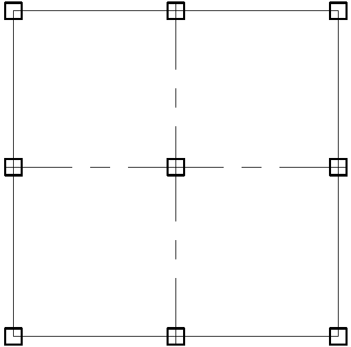
This structural system applies to buildings of up to about 75 m in height but is most economical for buildings of less than 50 m.
Shear Wall ‘Core’ Systems
This system consists of shear walls designed to resist lateral forces in two orthogonal directions. Figure 2 shows a typical arrangement, with shear walls, arranged close to the middle of the structure to house lifts, fire-escape stairs and other building maintenance, thereby providing a rigid structural base to withstand horizontal loads in two directions.
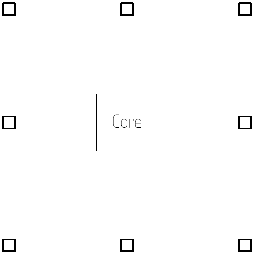
This structural system is also referred to as a ‘core system,’ the core is built to operate as a single vertical cantilever with enough lateral, torsional and bending rigidity to withstand the worst combinations of operation and ultimate conditions. A variation on this system involves the dispersal of additional shear walls uniformly across the building’s plan area. If this style is implemented, it is desirable to achieve a level of symmetry across the plan in the wall dimensions and positions to minimize twist of the structure. By virtue of the high lateral stiffness of the walls compared with the remaining vertical elements (columns) ensures that lateral loads are fully resisted by the main shear walls for this typology of framing. The columns are then only designed to withstand gravity loads, simplifying the design process and the construction of the slabs.
There are two major types of cores in tall building design: Concrete Core and Steel-framed Core.
Concrete cores are a more standard option for tall buildings because they are heavier hence provide more stiffness than steel cores. Also, with respect to constructability, structures that uses concrete core proceeds with the construction of the cores prior to the framing. Hence, the core and elevator shaft will allow for the use of climbing crane rather than having to erect separate tower cranes. Whereas, the motivation for steel framed cores is that they’re basically lighter than the former, since the total weight of the building is equally important for the foundation design. A lighter solution means that the building foundation is economical.
Generally, the shear wall system is adequate for buildings up to 120 m tall – Although having shear walls larger and longer within the limits of the floor plan will reach considerably greater heights.
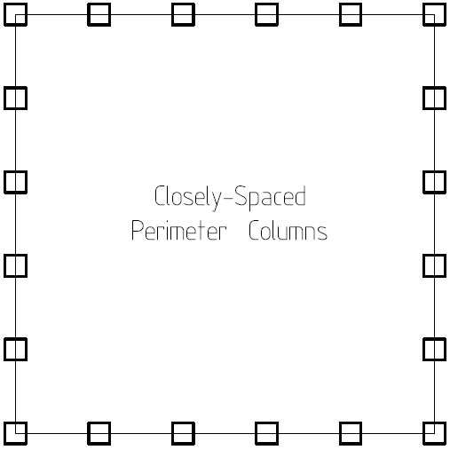
Tube Systems
In the design of very tall buildings, the tube system is one of the most common lateral stability solutions. It is designed to act as a vertical cantilevered hollow shell cylinder. This system allows the full width of the building footprint to be used to withstand the lateral loads on the building. It provides a very stiff structure but requires the structural elements to be arranged in some manner. Typically, columns are placed in relatively close centres of 2-4 m, connected by beams to create rigid frames around the perimeter (See Figure 3). The resulting form is a closed tube that acts as a hollow vertical cantilever. Steel, concrete, or composite construction can be used for this type of system.
This system was first introduced by Fazlur Rahman Khan from the firm Skidmore, Owings & Merrill (SOM) in 1970s. It was an innovative lateral stability system for designing a taller, more efficient building at that time. It has dramatic difference compared to the traditional structural system for multistory buildings, such as portal frame system, core wall strengthened by outrigger, etc.
The framed tube system is suitable for buildings with heights up to approximately 150-170 m
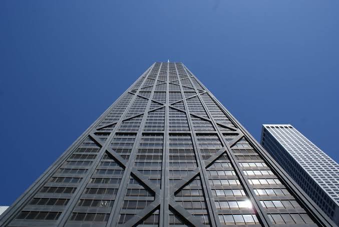
Tube design has variations. This include the tube in the tube; packed tubes; and braced tubes, where diagonal braces are mounted on the outer faces. Such variants usually provide increased flexural rigidity and allow increased spacing of the perimeter columns. Buildings up to nearly 300 m in height can be realized by implementing these structural systems. The John Hancock Centre in Chicago as shown in figure 4 is one of the famous examples of braced tubes.
Outrigger Braced-Systems
The outrigger system is used when it is desirable to use the maximum width of the building footprint and to mobilize the perimeter columns as a fundamental part of the structural structure to achieve the greatest flexural rigidity. Outriggers are one of the most widely used systems for relative regular floor plan. It is constructed using steel trusses, girders, concrete walls, or deep beams to connect the core and the columns at the perimeter. The outrigger trusses are normally one-story high, some even occupy several storey. The cores are normally located at the center of the building, whereas the outriggers extend out to the outer columns (See Figure 5).
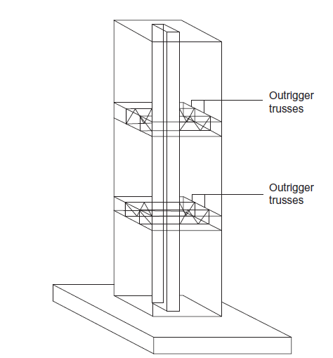
Thus, outriggers and the outer columns work together as a further restrain to the core wall. Under lateral load, the belt trusses act as lever arms that directly transfer axial stresses to the perimeter columns. The bending, axial tension, and compression of the outer columns connected to the outriggers help resist the external moments of the structure. This resistance therefore enhances the overall stiffness of the core, helps in reducing lateral deflections, and overturning moments. The outrigger columns work together particularly by helping to restrain the rotation of the core. Overall, the major advantage of using outriggers is to resist the rotation of the core and significantly reduce the lateral deflection and overturning moment.
There are several different types of outrigger system, such as steel outriggers, concrete outriggers, and hybrid outrigger (using both concrete and steel material).
- Steel Outriggers: are extensively used in a lot of tall buildings as most of tall buildings are either steel or composite structural system. In most tall buildings, the outrigger is a truss, a storey height deep.
- Concrete Outriggers: Under extreme lateral loading, the outrigger system must be very stiff, hence the benefit of concrete outrigger system verses steel is high stiffness and sometimes low cost.
- Hybrid Outriggers: Steel outriggers are not as stiff as concrete outriggers. But the latter is very brittle. Hence a hybrid outrigger is a structure in which both steel and concrete work compositely to enhance the structural performance of the lateral stability system.
- Damper Outriggers: A damper outrigger comes in handy, in the event of an extreme loading condition such as earthquake, the structural system should be able to dissipate energy, thereby maintaining structural robustness against collapse.
This outrigger-braced system is used to build structures with a height of up to 350 m, or super-tall buildings. Nevertheless, the braced system principle of using outriggers can be extended to much shorter constructions.
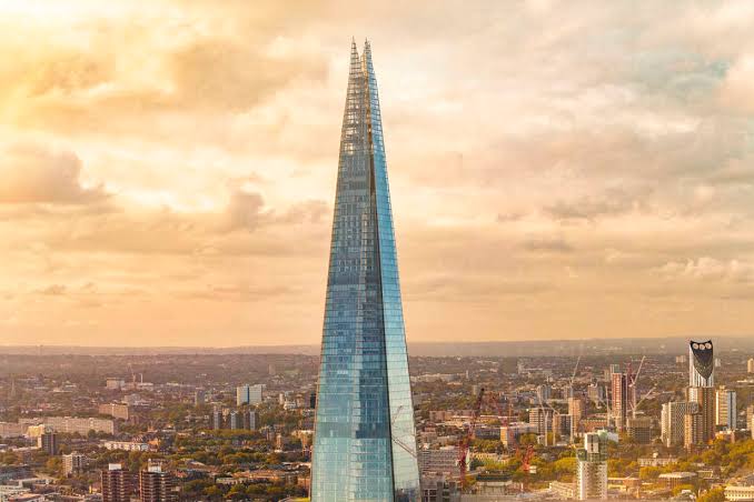
Figure 6 is a picture of the shard in the U.K, the tallest building in London and the sixth tallest building in the whole of Europe. It is a perfect example of a building that uses the outrigger system to resist lateral forces.
See: Fundamentals of Lateral Stability
Typically, for many tall buildings, a combination of the systems described in the preceding sections may be applicable. Deciding on which to use will depend on a lot of factors. Generally, engineers should allow a reasonable amount of time to determine the most appropriate structural system for each case.
Sources & Further Reading
- The Concrete Centre Publication (2014)-Tall Buildings-Structural Design of Tall Buildings up to 300m -A cement and concrete industry publication.
- Feng F. (2018)– Design and Analysis of Tall and Complex Structures (1Ed)- Elsevier Ltd.
- The Concrete Centre Publication (2018)-Guidance on the design and construction of building tall in concrete – Concrete Tall Buildings.
Thank You!!!