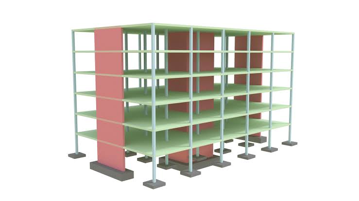
A structure does not only transfer gravitational forces to the ground, it must do so for several other lateral forces applied . The components that hold the structure standing against these lateral forces is called the ‘stability system’ or, often, the ‘lateral load-resistant system’.
Achieving lateral stability in structures is usually dependent on the geometry and the materials from which the structure is constructed. For instance, steel beams support a concrete floor slab, or a timber-roof frame rests on a masonry wall. Every one of these elements must work together to safely move horizontal loads to the ground.
This post is set-out to introduce developing and identifying defined load paths within structures in order to ensure lateral stability.
Components of a Lateral Stability System
For every structure resisting lateral loads, there are four types of elements that can be found:
- Steel bracing
- Shear cores and walls
- Portalization
- Diaphragms.
For certain cases, they are used in tandem with each other to produce a more stable structure.
These elements can be categorized into the horizontal bracing elements and vertical bracing elements.
Horizontal Bracing Elements
Horizontal elements are those that are in a horizontal, or near-horizontal plane (typically associated with floor and roof planes). They are required to transfer lateral forces to the vertical stability elements. There are two types of horizontal system: diaphragms and triangulated bracing (the latter being sometimes referred to as a wind girder).
Diaphragms
A diaphragm is the part of a structure that provides bracing in its plane. Usually, these are floor slabs and roof cladding, but they can also be in vertical cladding elements. Diaphragms are tied back to vertical elements of the structure that provide lateral stability. They prevent structures from ‘racking’ or rotating about an axis. There might be some instances where diaphragms may not have sufficient strength to resist lateral loads. In such instances, additional horizontal bracings must be provided or the floor diaphragms strengthened.
Triangulated Bracing
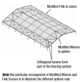
In the absence of a sufficiently stiff diaphragm, Horizontal bracing may be used, in the form of steel bracing. The bracing is arranged in either the modified warren truss or the modified fink truss format as shown in Figure 1. The modified fink truss is more suited for tension bracing, in both cases the floor or beams act as part of the horizontal stability system and therefore must be designed for tension or compression in addition to flexure and shear.
Vertical Bracing Elements
The vertical elements are those that are in a vertical or near-vertical plane. They are the parts of the lateral stability system responsible for transferring the lateral loads down to the foundations. These vertical elements consist of one or more vertical elements with individual elements fixed or pinned at the foundation.
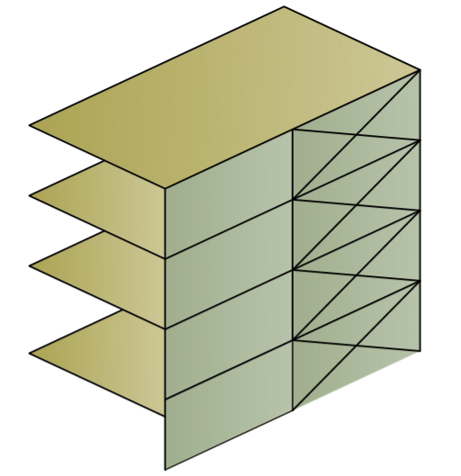
Steel Bracing
This is one of the most well-known methods of providing lateral stability. Bracing (Figure 2) consists of diagonal elements, working from the ground up in a similar fashion to a cantilevering vertical truss. In order for bracings to be effective, it must be present at each and every level of the structure down to the foundations. If bracings are discontinuous at one level significant lateral forces may be passed into the elements, which could be quite catastrophic if they weren’t designed to withstand such forces.
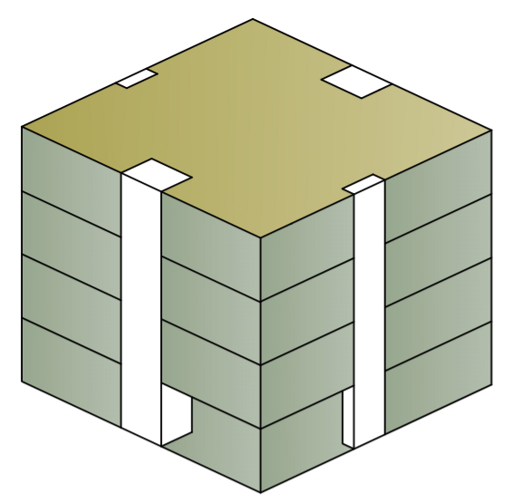
Shear Wall & Cores
Shear wall and cores are concrete vertical elements within a structure providing lateral stability (Figure 3). The rest of the structure is built around them and they normally work in combination with floor plates and roofs acting as diaphragms. These can also be combined with steel bracing. Cores generally serve as vertical access to the entire structure through lifts and stairs and are usually placed in line with the centre of the structure in an effort to reduce torsional effects. However, in reality, there will always be a difference between the centre of the stiffness of the structure and the centroid of the applied wind loads. As a result, some torsional stresses may be induced in the shear walls and cores as a result of eccentric lateral loads
Portalization is another method of lateral stability, it is based on the concept of portal frames whose connections are designed to resist lateral forces
Positioning of Lateral Restraints
As mentioned in the preceding section, the location of a vertical element within a structure has an effect on their response to lateral forces. Simply dispersing them within the structure does not necessarily guarantee lateral stability, as excessive twisting could be generated if significant eccentricities exist between the centre of area of the vertical elements and the point of application of the lateral loads.
Positioning Steel Bracings
Vertical steel bracing is usually used in combination with other components that provide lateral support, be it a shear wall, a core or a sway frame. These typically have an influence on the architecture of the structure, and their location is generally dictated by both the architectural needs and the spatial constraints of the building.
Positioning Shear Walls & Cores
The relative location of the shear cores and walls against the resulting force produced by the applied horizontal loads should ideally be as near as possible to the centre of the applied forces. It is required to minimize the effect of combined bending and torsion.
When positioning vertical bracing elements, it is important to remember their stiffness compared to the other vertical elements in the structure that also provide lateral stability. This is because the lateral loads are being shared according to their relative stiffnesses.
Strategies for ensuring Lateral Stability
A certain understanding of alternative options (and their consequences) is needed before attempting to implement a particular strategy for lateral stability. A system must always:
- Provide linear resistance in two orthogonal horizontal axes.
- Provide torsional resistance about a vertical axis.
- Provide the said resistance to all parts of the structure.
To buttress the points made above, consider figure 4 showing various lateral stability solutions for a building.
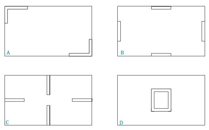
Structure ‘A’ boasts a solution which orthogonally braces the structure in both directions. However, there is the possibility that if one of the vertical bracing elements is damaged unintentionally, the entire structure may become unstable.
Structure ‘B’ is the most effective, but not architecturally sound solution. Nonetheless, it does have flexibility so that if one of the vertical bracing systems fails, it would not leave the building in an unsafe condition.
Structure ‘C’ is a poor solution as off-centre wind forces within the structure can produce major cant torsion. If the structure was also made predominantly from concrete, then shrinking inside it would also produce major stresses that can not be alleviated
Structure ‘D’ is marginally better than ‘C,’ but is still susceptible to off-center wind forces and would also cause substantial torsion in the structure.
References & Further Reading
The Institution of Structural Engineers (2014) -(Part 1 & 2) Stability of Buildings-General Philosophy and Framed Bracing: The Institution of Structural Engineers
BS EN 1990: UK National Annex to Eurocode: Basis of Structural Design.
The Institution of Structural Engineers (2012) -Principles of Lateral Stability-Technical Guidance Notes(level 2): The Institution of Structural Engineers
Thank You!!!
online pharmacy discount code 2018 – buy cheap tadalafil canadian pharmacy cialis brand
viagra 100 mg – viagra 50 viagra coupons
tadalafil soft tablets 20mg – tadalafil lowest prices canada generic cialis online prescription
ivermectin without prescription – buy stromectol uk stromectol where to buy
play for real online casino games – winslotgms casino online gambling
what is erectile dysfunction – generic ed pills best non prescription ed pills
deltasone tablet – prednisone 10mg without prescription medicine prednisone 20mg tablets
tadalafil lowest price – Buy cialis low price paypal cialis canada
stromectol over the counter – ivermectin buy australia stromectol 3 mg dosage
Дом Гуччи смотреть онлайн
hims ed pills – natural ed drugs what blood pressure medication does not cause erectile dysfunction
смотреть фильмы онлайн бесплатно
ventolin inhaler – buy albuterol online ventolin over the counter
buy cytotec online singapore – how much is misoprostol cytotec over the counter uk
buy doxycycline 100 mg tablet – doxycycline order uk buying doxycycline uk
generic neurontin 600 mg – canada where to buy neurontin synthroid 0.0125 mg
where can i buy generic viagra in usa – cheap viagra canada
http://buysildenshop.com/ – Viagra
cialis viagra online canadian
buy generic tadalafil in us – tadalafil pharmacy
cheapest generic vardenafil – brand name vardenafil online how does vardenafil work
https://buystromectolon.com/ – Stromectol
price of stromectol – stromectol us ivermectin 6 mg tablets
prednisone 54760 – prednisone steroids prednisone 13 mg
Wow, this article is pleasant, my sister is analyzing such things, therefore I
am going to let know her.
buy accutane in india – accutane 20 mg daily generic accutane online pharmacy
вот
amoxil 500 mg generic name – buy amoxicilina 500 mg from mexico rx amoxicillin 500mg
Best Buy Stendra Direct With Free Shipping
generic medrol online no prescription – cheap methylprednisolone lyrica 225 mg
Propecia
Cialis
buy viagra online without a prescription – Buy pfizer viagra online order viagra canada
canada ed drugs reputable online pharmacies in india – cvs prescription prices without insurance
Levitra purchase
overseas viagra
cialis 100mg real – Buy no rx cialis where to buy tadalafil cheap
Клятва врача
https://buytadalafshop.com/ – cheapest place to buy cialis
http://buypropeciaon.com/ – Propecia
ivermectin cream uk cheap ivermectin – ivermectin oral
Stromectol
stromectol tab – xivermectin ivermectin pill cost
ivermectin price ivermectin for humans – ivermectin price canada
prednisone 54092 – prednisone 5 mg buy online prednisone online
lasix furosemide – order clomiphene 50mg buy lasix 100mg