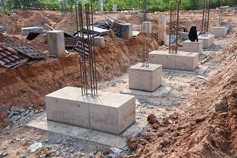
This article provides an overview of how to estimate settlement of spread foundation with a focus on Eurocode 7. The article also contains fully worked example.
When undertaking designs based on the limit state theory, two limit states mostly discussed– the ultimate limit state and the serviceability limit state. Within the context of geotechnical design of foundation, the ultimate limit state relates to estimating soil bearing capacity in order to ensure that loads applied on any given soil do not exceed the value. Serviceability corresponds to the conditions beyond which specified service requirement for a structure or structural member are not met. Serviceability in foundation design relates to ensuring that movement of the foundation is kept within acceptable limit.
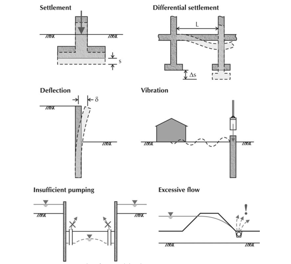
Examples of situations where serviceability is a concern are shown in Figure 1. From left to right, these include: (top) the settlement, s, of a pad footing due to its self-weight and any imposed loads must not exceed the project-specific limiting settlement and the differential settlement, Δs, of foundations for a framed structure must be within specified limits; (middle) the horizontal deflection, δ, of a retaining wall due to unbalanced earth pressures must be within specified limits and vibration due to machinery must not cause discomfort to neighbors; and (bottom) the rate at which water is pumped from a basement must be sufficient to prevent heave underneath the basement and the capacity of the pump, on the downstream side of a dam, must be sufficient to remove water flowing underneath the dam.
In traditional geotechnical practice, serviceability limit states have been avoided by a variety of means, such as: for foundations, limiting the bearing pressures underneath the foundation to ‘allowable’ (conservative) values; for piles, by applying large safety factors to base and shaft capacities; and for embedded retaining walls, using ‘mobilization factors’ to reduce the passive earth pressure assumed to achieve moment equilibrium.
All these methods are fundamentally the same. They attempt to reduce settlement by ensuring failure has a sufficiently remote possibility of occurring. Eurocode 7 acknowledges that deformations can be kept within required serviceability limits provided ‘a sufficiently low fraction of the ground strength is mobilized’; a value of the deformation is not needed; and comparable experience exists with similar ground, structures, and method of application.
Unfortunately, the standard does not specify (other than for spread footings, discussed below) how low this fraction should be. Asides this, there are instances where the code specifically requested for settlement to be estimated, for instance in foundations founded in clay where the ratio of bearing resistance and characteristics load applied is less than 3.
Thus, this article presents a method for estimating settlement according to the recommendations in Eurocode 7.
Verification of Settlement to Eurocode 7
Verification of serviceability involves checking that design effects of actions (e.g. settlements) do not exceed their corresponding design limiting values (i.e. limiting settlements).
Ed = the design effects of actions Cd = the limiting design value of the relevant serviceability criterion. The applied settlement and limiting settlement correspond with the design effects of actions and limiting design value respectively in the context of settlement calculation.
Annex F of EN 1997-1 presents two methods to evaluate settlement. In the stress-strain method, the total settlement of a foundation may be evaluated by, first, computing the stress distribution in the ground due to the foundation loading (using elasticity theory for homogeneous, isotropic soil); second, computing the strain in the ground from those stresses using an appropriate stress-strain model (and appropriate stiffness); and, finally, integrating the vertical strains to find the settlements.
Other methods for calculating settlements (from in situ tests) are given in the Annexes to EN 1997-2 (see the list in Chapter 4). Eurocode 7 emphasizes the fact that settlements calculations ‘should not be regarded as accurate. They merely provide an approximate indication’.
Applied Settlement
The settlement of spread foundations has three components each of which needs to be considered. These components include:
- Immediate settlement (s0) due to shear at constant volume in saturated soils (or with volume reduction in partially-saturated soils)
- settlement caused by consolidation (s1)
- settlement caused by creep (s2)
Hence, the previous inequality can be re-written for footings as follows:
s_{Ed}=s_0+s_1+s_2 \le s_{Cd}Where sEd is the total settlement (an action effect) and sCd is the limiting value of that settlement.
Immediate Settlement
Immediate settlement refers to the immediate compression of the soil under a foundation load without any time-dependent consolidation effects. It’s essentially the settlement that occurs almost instantaneously upon the application of the load. There are several methods of estimating initial settlement. Christian and Carrier provided a method to estimate the value based on the elastic properties of the soil and the applied load. Their approach often involves considering the soil as an elastic material with certain properties such as modulus of elasticity and Poisson’s ratio.
According to Christian & Carrier the immediate settlement of a spread foundation can be estimated using the following equation:
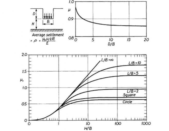
s_0 =\frac{\Delta q_d B \mu_0 \mu_1}{E_{uk}}Where: ∆qd represents the change in applied stress due to the foundation load. B is the width of the foundation. μ0 and μ1 are the settlements factors obtained from charts reproduced in this article as Figure 2 based on the dimensions of the foundation and the depth of influence. Euk is the modulus of deformation of the soil.
Consolidation Settlement
The consolidation component of the settlement refers to the gradual decrease in volume of the soil layer over time due to the expulsion of water from the void spaces between soil particles when subjected to a sustained load. There are also several methods available for estimating consolidation settlement. The outlined method in this article involves dividing the soil layer into N sub-layers and utilizing influence factors from Fadum’s chart to compute the consolidation of each layer. The sum total of each layer gives the consolidation component. Here’s a brief step to follow:
Dividing the Soil Layer into Sub–Layers: The soil layer is divided into N sub-layers of equal thickness. This division allows for a more accurate analysis of settlement distribution within the soil profile.
Depth Calculation for Sub-Layers: The depth below the base to the center of each sub-layer, zi is calculated using the formula below, where Δt is the thickness of each sub-layer and i ranges from 1 to N. This helps in determining the position of each sub-layer within the soil profile.
z_i= (\Delta t \times i) - \frac{\Delta t}{2}Normalized Foundation Half Breadth Calculation: The normalized foundation half breadth (mi) is calculated for each sub-layer using the formula mi = B / (2zi), where B is the width of the foundation. This factor represents the influence of foundation shape and size on settlement distribution within each sub-layer.
m_i=\frac{B}{2z_i}Obtaining Influence Factors from Fadum’s Chart: Influence factors (Iqi) are obtained from Fadum’s chart using the normalized foundation half breadth (mi). Fadum’s chart (Figure 4) provides a graphical representation of influence factors based on foundation geometry and soil properties.
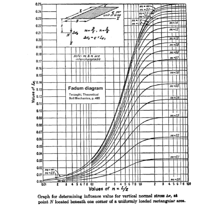
Change in Vertical Stress Calculation: The change in vertical stress (Δσvi) in each sub-layer is calculated using the influence factors obtained from Fadum’s chart. The formula used in this case is presented below, where Δqd represents the change in applied stress due to the foundation load.
\Delta\sigma_{v_i}=4I_{q_i} \Delta q_dSettlement Calculation for Each Sub-Layer: The settlement in each sub-layer (ρci) is calculated using the formula below, where mvk represents the coefficient of volume compressibility and Δt is the thickness of each sub-layer. This step determines the amount of settlement occurring in each sub-layer over time.
p_{c_i}=m_{vk} \Delta \sigma_{v_i} \Delta tTotal Consolidation Settlement: The total consolidation settlement (s1) is obtained by summing up the settlements in all sub-layers using the formula Σ(ρci) for i = 1 to N. This gives the overall settlement of the soil layer due to consolidation under the applied load as
s_1 = \Sigma {p_{c_i}}Creep Settlement
Creep settlement refers to the additional settlement that occurs in a soil over time under a sustained load, after primary consolidation has completed. It is a result of the slow, time-dependent deformation of the soil structure. Determining creep settlement typically involves laboratory tests, empirical correlations, or mathematical models.
Limiting Settlement
Annex H of EN 1997-1 also provides guidance on allowable deformations in open-framed structures, infilled frames, and load bearing and continuous brick walls (see table below). These guidelines apply to normal structures, not to extraordinary structures or to structures subject to markedly non-uniform loading. The limiting value for settlement is taken as 50mm.
Worked Example
An infinitely long strip footing (Figure 4) of footing width 2.0m, is required to carry a design permanent action of 175kN/m and an imposed loading of 100kN/m. The footing is founded on a medium strength clay at a depth of 1.2m from the natural ground level. Assuming a rigid layer underlies the footing at a depth of 5m, estimate the overall settlement of the strip footing. Given that the clay’s undrained Young’s modulus is Euk = 26.8Mpa and its characteristic coefficient of compressibility mvk = 0.14m2/MN
As discussed in the last section, the applied settlement involves three components, immediate, consolidation and creep. However, since estimating creep component often requires empirical correlations. Its value is ignored in this worked example. Albeit the value is often negligible.
Immediate Settlement
To determine the immediate component, we must first estimate the pressure exerted by the footing on the soil mass:
s_0 =\frac{\Delta q_d B \mu_0 \mu_1}{E_{uk}}\Delta q_d=\frac{w_g+w_q}{B} =\frac{175+100}{2} = 137.5kN/m^2Settlement factor for D/B is d/b =0.75 which gives μ0 = 0.91 (from chart)
Settlement factor for H/B is (dR-d)/B = 1.75 which gives μ1 = 0.55 (from chart)
Therefore, immediate settlement:
s_o=\frac{137.5\times2\times0.91\times0.55}{26.8} = 5.1mmConsolidation Settlement
Divide clay layer into N = 5 sub-layers of thickness Δt (dR − d)/N = 0.7 m For each layer i = 1 . where N is the depth below base to the centre of each layer is given by zi=(Δt × i) /Δt/ 2. And the normalized foundation half breadth by mi =B/2zi. The influence factor Iqi Iq.∞ = (mi) can be found from Fadum’s chart. The change in vertical stress in each layer is Δσvi = 4Iqi = Δqd and the settlements of each layer ρci=mvkΔσviΔt
z=\begin{pmatrix}
0.35\\
1.05 \\
1.75\\
2.45\\
3.15
\end{pmatrix} m=\begin{pmatrix}
2.86\\
0.96 \\
0.57\\
0.41\\
0.32
\end{pmatrix} I_q=\begin{pmatrix}
0.22\\
0.21 \\
0.15\\
0.13\\
0.11
\end{pmatrix}
\Delta \sigma_v=\begin{pmatrix}
121\\
116 \\
83\\
72\\
61
\end{pmatrix} p_c=\begin{pmatrix}
11.9\\
11.4 \\
8.1\\
7.1\\
6.0
\end{pmatrix} s_1 = \Sigma {p_{c_i}} \\11.9+11.4+8.1+7.1+6.0= 44.5mmTherefore, total settlement of strip footing is given as:
s_{Ed}=44.5+5.1 =49.6 \le50mm \quad o.kAlso see: Geotechnical Design of Spread Foundations to Eurocode 7
Sources & Citation
- Christian, J.T. and Carrier W.D. (1978). Janbu, Bjerrum and Kjaernsli’s chart reinterpreted, Canadian Geotechnical Journal, Vol. 15, pp. 123–8.
- B.M Das and N. Sivakugan (2019). Principle of Foundation Design. Ninth Edition, SI Edition
- Bond A and Harris A (2008) Decoding Eurocode 7. Taylor & Francis, London, UK.