This article explores the design of posttensioned flat slab based on Eurocode 2 using a practical worked example
A Posttensioned flat slab is the simplest type of posttensioned slab. It is essentially a flat slab that has been enhanced using high-strength steel tendons to apply compression after the concrete has set thereby reducing deflection of the concrete floor. Post tensioned slabs offers the slimmest type of floor that can be achieved overall with the use of concrete.
Recall, the previous article presented a general guide on how to approach the design of posttensioned slab. It highlighted the benefit it had over traditional reinforced concrete slabs. Some of the benefits include, extensive usage, especially in high-rise constructions being the slimmest structural choice, the dead load from the slab is relatively smaller this consequently means that the loads expected at foundation would be smaller, therefore they have an extensive usage in high-rise construction readily. They are also very accessible for spans exceeding 7m and being able to economically support spans up to 13m × 13m.
The last article however did not delve into specific details on how they may be designed. Thus, this article explores the design of posttensioned flat slab and demonstrate the design procedure using a worked example based on Eurocode 2.
Design of Posttensioned Member
The design of post-tensioned elements is a highly iterative process that in practice is carried out using specialist computer software. To enable a design that can be carried out using hand, significant simplifying assumptions will be required. Therefore, the design methods presented below are strictly for preliminary design only and assume some understanding of post-tensioning design and construction. For detailed design reference should be made to TR43 post-tensioned concrete floors or similar references.
In the case of a posttensioned slab, an initial the slab thickness is first selected, the next step is to determine the amount and distribution of prestress. This process typically involves load balancing, where the transverse stresses induced by the draped tendons in each direction counteract a portion of the load. By doing this, the slab remains flat under the balanced load, avoiding any curvature and experiencing only the resulting longitudinal compressive P/A stresses. This approach ensures that the primary structural behavior under balanced loading conditions is well understood and managed.
The remaining unbalanced load, however, plays a crucial role in the overall performance of the slab. This load must be considered when assessing the service load behavior of the structure. Specifically, it is essential for estimating load-dependent deflections, which affect the slab’s long-term performance and usability. Additionally, evaluating the extent of cracking and the effectiveness of crack control measures is critical to ensure the slab’s durability and structural integrity.
Load Balancing
The traditional design method is ‘load balancing’ where the prestress on the concrete element is designed such that it imposes an upwards load on the element which counteracts the gravity loads on the element (see Figure 1). Usually only a part of the imposed loads is designed to be balanced by the prestress, say the dead loads only.

The balancing forces on the element depend on the profile of the tendon and are therefore chosen to match the shape of the bending moment diagram. By following the profile of the bending moment diagram the tendon will be located at the tension face for both the maximum hogging and sagging moments. The balancing forces can be calculated as follows:
w=\frac{8aP_{av}}{s^2}Where: w= udl due to the parabolic profile a = drape of tendon measured at centre of profile between points of inflection; Pav = average prestressing force in tendon; s = distance between points of inflection
Stresses
The stress in the element can be calculated as follows:
Stress at the top of the section
\sigma=\frac{P}{A_c}+\frac{M_b}{Z_t}Stress at the bottom of the section
\sigma=\frac{P}{A_c}+\frac{M_b}{Z_b}Initial Design
The serviceability condition is usually the critical design criterion. At the initial stages it is reasonable to check the stresses at SLS and assume that the ULS requirements can be met in detailed design. Modern design software will allow further iteration and potentially a reduction in reinforcement. The following prestresses (i.e. P/A) are a good guide for initial design:
- Slabs: 1.4 – 2.5 N/mm2
- Beams: 2.5 – 4.5 N/mm2
For slabs, punching shear should also be checked (see 3.12.3), because this can often be a critical factor. A short, heavily loaded transfer beam may also be critical in shear, and this may need checking.
The tendon profile should be idealised to simplify the calculations
Worked Example
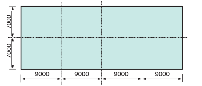
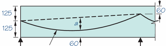
Figure 2 Below show a post-tensioned floor layout for a proposed mixed-use development. Carry out sufficient number of calculations to size the posttensioned floor assuming that the superimposed dead load on the floor and imposed load are 1.5kN/m2 and 5kN/m2 respectively. Design for class 3 serviceability condition and use Concrete class C32/40. Note: Strand diameter =12.9mm; Distance to centre of strand =60mm (See Figure 3) for tendon profile in the most critical span.
Initial Sizing
Using a span: effective depth ratio for PT slab, we have:
=\frac{9000}{36}=250mmTherefore, we’ll use 250mm thick posttensioned flat slab.
Geometry
We need to work out the geometrical properties of the components of posttensioned slab, including those of the concrete section and that of the strand used for the pre-stressing.
Area of Concrete; Ac
The area of the concrete section is given as:
A_c=bh=7000\times250=1750\times10^3mm^2
Second Moment Area of Section, I
The second moment area of the concrete section is taken about the y-y axis of the slab and is given as:
I=\frac{bh^3}{12}=\frac{7000\times250^3}{12}=9.11\times10^9mm^4Distance to Extreme Fibres from Neutral axis
Since the concrete section is rectangular, the neutral axis would be in the centre of the concrete section, thus, this distance is given as:
y_b=y_t=h/2 =250/2=125mm
Section Modulus, Z
The section modulus of the concrete section is given as:
z=\frac{I}{y}=\frac{9.11\times10^9}{125}=72.9\times10^6mm^3Drape, a
Looking at the idealized tendon shape (Figure 3). The drape can be obtained as follows:
a=250-60-60-65/2=98mm
Number of Strands Required
Having determined the geometrical properties of the post-tensioned flat slab, the next procedure involves determining the number of strands that will be required in the slab using the characteristics value of the maximum force a single strand can resist
For strand ‘12.9’ super, characteristics value of maximum force a single stand can resist = 186kN
Initial Prestress Force
Recall that the initial pre-stress force is always 80% of the characteristics value of the force. Thus:
0.8\times186=149kN
Pre-stress in Service Condition
Allow for 10% loss at transfer and 20% loss at service, check in detailed design, we have the pre-stress in service condition given as:
=0.7\times149= 104kN
Balanced Load with Prestressing
Therefore, the balanced load from pre-stressing to be balanced is given as:
P=\frac{ws^2}{8a}=\frac{7\times6^2}{8\times0.0098}=4339kNSo, number of tendons required to resist this force will be given as:
=\frac{4339}{104}=41.7Try a 8 x 5 strand per panel. Total force is given as:
5\times8\times104=4160kN
Flexural Actions @ SLS
To determine the balanced moment, we must first determine the applied load on the floor in UDL and the balancing load. The applied is obtained by multiplying the applied floor load without partial factors for the permanent actions and with the partial factor for the variable actions with the width of the floor.
Applied load
w_a=(6+1.5\times5)\times7= 87.5kN/m
Balancing Load
=\frac{8aP}{s^2}=\frac{8\times0.098\times4160}{9^2} =40.2kN/mTherefore, the balanced moment can be calculated from the following equation:
M=\frac{(w_a-w_b)l^2}{10}=\frac{(87.5-40.2)9^2}{10}=383.1kN.m
Stresses
Having determined the flexural actions, we can then determine the stresses to find out if they are within the acceptable limits.
Compressive stress at the topmost fibre
\sigma_t=\frac{P}{A_c}+\frac{M_b}{Z_t}=\frac{4160}{1750}+\frac{383.1}{72.9}=7.7MpaFor class C32/40 allowable compressive stress is 13.2 N/mm2 ∴ OK
Tensile stress at the bottommost fibre
\sigma_t=\frac{P}{A_c}-\frac{M_b}{Z_t}=\frac{4160}{1750}+\frac{383.1}{72.9}=2.9MpaFor class C32/40 allowable tensile stress is 5.5 N/mm2 ∴ OK
Finally, shear and punching shear check must be carried out. This is done in the same vein as it is done for a traditional flat slab.
See: Designing a Flat Slab – Worked Example
Sources & Citations
- The Concrete Society (2005) Technical Report No. 43: Post- tensioned concrete floors: Design handbook (2nd ed.), Camberley, UK: The Concrete Centre
- Goodchild C. H., Webster R. M. and Elliott K. S. (2009) Economic Concrete Frame Elements to Eurocode 2, Camberley, UK: The Concrete Centre
- Brooker O. (2006) Concrete Building Scheme Design Manual, Camberley, UK: The Concrete Centre
- Institution of Structural Engineers (2015) Design of Post-tensioned Slabs. Concrete Design Guide, The Structural Engineer.