A spiral staircase is a type of staircase that follows a helical or circular path, with each step or tread positioned around a central column or a post. The primary advantage of spiral staircases over the more traditional stair design such as the ‘dog-legged’ or ‘open-well’ type is to the effect that it takes up less space, making it very popular choice for small residential apartment and as escape stairs for dwellings constraint by space. Additionally, its often-unique design adds dramatic and visually aesthetic elements to the overall building design.
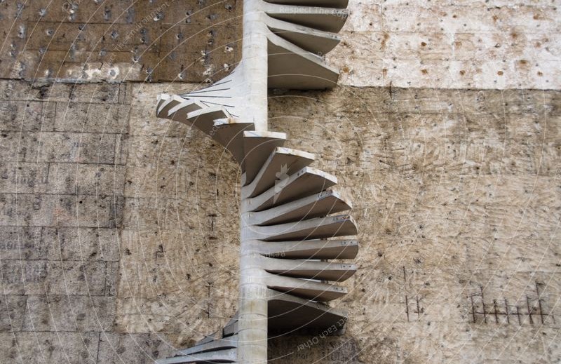
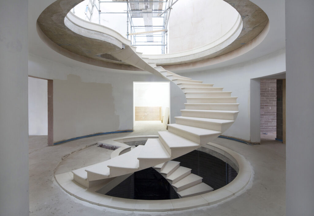
A spiral staircase must not be confused with an helicoidal staircase. Although they both assume the curved/helical form (Figure 1), however, they are completely different in analysis and design. While a spiral staircase makes of a support in the form of column or post, a helical staircase is left floating and only supported between floors. Thus, while a spiral staircase tends to be idealized and designed as simply a cantilever slab stemming from a central column, the helicoidal staircases, by virtue of their geometry involves a rather complicated analysis procedure, involving a consideration of an interaction between vertical/lateral moment with shear, axial force and torsion.
Due to the complexity in the analysis of helicoidal staircases, this article is constraint to the analysis and design of spiral staircases only. In a later discussion, the intricacies of designing helicoidal staircases will be presented.
Structural Analysis & Design
As earlier stated, a spiral staircase consists of at least two elements: the threads; and the central column. The central column can be seen as the backbone of the staircase, and it provides support for the entire staircase. The central column is usually made in reinforced concrete or steel section. When reinforced concrete is used, the columns are traditionally circular in cross-section. In design, the columns are designed as axially loaded with some minor eccentricities allowed.
The treads/steps as described earlier is idealized as a cantilever slab spanning from the central column to the edge of the stair. The steps are designed for flexure and a check for deflections which tends to be critical when the span is above 1.5m. Typical depth of the section would vary between 100-175mm depending on the span.
Worked Example
The plan and section of an escape staircase for a proposed residential development is shown in figure 2. Provide approximate hand calculation to determine the quantity of reinforcement required in the steps and central columns. (Use C20/25 and fy = 410Mpa RCC).

Actions
To determine the design loads on the staircase, we must first determine the area of each step. This would consist of the area of the cantilevered region itself and the area around the central column. See figure 3.
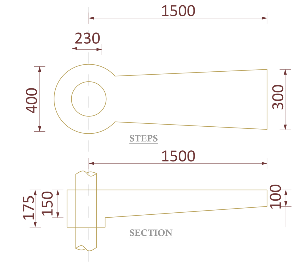
If we apply basic rules of trigonometry, the area of each step can be determined as: area of cantilevered region = 0.173m2; Area around central column = 0.08m3. Therefore, total area = 0.253m3.
Permanent Actions
a) \quad self \quad weight \\=(0.173\times0.15\times25)+(0.08\times 0.175\times25)\\=1kN
b)\quad finishes\quad =(0.253\times 1.5)=0.38kN
G_k=1+0.38=1.38kN
Variable Actions
a)\quad imposed\quad load = (0.253\times 2)=0.51kN
Design Value of Actions
Utilizing eqn 6.10 of BS EN 1990; we have:
n_{s}=\quad 1.35{ G }_{ k }+{ 1.5Q }_{ k }w=(1.35\times1.38)+(1.5\times0.51)\\ \qquad \qquad \qquad = 2.63kN
Flexural Design
Recall, the steps are idealized as cantilever; hence the design moment is given as:
Bending Moment
M_{Ed}=\frac { w l }{ 2 } = \frac {2.63 \times1.5}{ 2 }=1.97kN.m{ d }=h-\left( { c }_{ nom }+\phi /2 \right)\\=150-\left( 25+12/2 \right) =119mmb=200mm (column\quad end)
k=\frac { { M }_{ Ed } }{ b{ d }^{ 2 }{ f }_{ ck } } =\frac { 2.63\times { 10 }^{ 6 } }{ 200\times { 119 }^{ 2 }\times 20 } =0.04z=0.95d=0.95\times119=113.05mm
{ A }_{ s,req }=\frac { { M }_{ Ed } }{ 0.87{ f }_{ yk }z } =\frac { 2.63\times { 10 }^{ 6 } }{ 0.87\times 410\times 113.05 } \\=65.22{ mm }^{ 2 }Use 2Y12mm bars Top. (As, prov = 226mm2).
Deflection Verification
Deflection is satisfied by ensuring that the actual span – depth ratio is less than the limiting value.
Limiting Span-Depth Ratio
{ \left[ \frac { l }{ d } \right] }_{ limit }=N\cdot K\cdot F1\cdot F2\cdot F3\rho =\frac { { A }_{ s,req } }{ { A }_{ c } } =\frac { 65.22}{ \left( 200\times 119 \right) } =0.0027 { \rho }_{ o }={ 10 }^{ -3 }\sqrt { { f }_{ ck } } ={ 10 }^{ -3 }\sqrt { 20 } =0.0045N=11+\frac { 1.5\sqrt { { f }_{ ck } } { \rho }_{ o } }{ \rho } +3.2\sqrt { { f }_{ ck } } { \left( \frac { { \rho }_{ o } }{ \rho } \right) }^{ 3/2 } \\ =52.9F1=1.0; F2=1.0; K=0.4(cantilever)
F3=\frac { 310 }{ { \sigma }_{ s } } \le 1.5By \quad inspection\quad F3=1.5
\left[ \frac { l }{ d } \right] _{ limit }=52.9\times 0.4\times 1.0\times 1.0\times 1.5\\ =31.7Actual Span – Depth Ratio
{ \left[ \frac { l }{ d } \right] }_{ Actual }=\frac { span }{ effective\quad depth }= \frac { 1500}{ 119 } =12.6The limiting span-effective depth ratio is greater than actual; thus, deflection is deemed satisfactory.
See: Design of Stringer Beam in Staircases to EC 2 | Worked Example
Column Design
Recall, the central column is designed as axially loaded; hence, since there are about 18 steps, the cumulative axial load on the central column is = (18 x 2.63) =47.3kN. By inspection, this is small, therefore minimum area of steel can be provided.
Use 6Y12 and Y8-125mm links in central column
