The use of masonry as a structural material dates back into antiquity with evidences from as far back as 10,000 years ago. Masonry was mostly utilized in the construction of major load bearing components of structures, bridges, buildings water retaining structures et al. However, with the advent of steel and concrete technologies in the 19th and 20th century, masonry took less prominent role as a structural material. It has been relegated too different forms of building cladding, rarely carrying any loads. Of course, except in very few instances where they are required to carry lateral actions, perhaps from wind on a masonry cladding or earth pressure onto a masonry retaining wall.
This article describes the process of designing a laterally loaded masonry wall to Eurocode 6. It will highlight material properties of masonry and the relationship it has with geometry and support condition when utilized as a structural material. The reader is advised to get a copy of the applied codes of practice as all tables, charts and figures are not reproduced in the article but only referenced. Copies of these codes can be obtained from the hyperlinks below.
- Eurocode 6 – Design of Masonry Structures (Part 1)
- UK National Annex to Eurocode 6 – Design of Masonry Structures (Part 1)
Prior to carrying out any design in masonry, an in depth understanding of certain parameters much be fully appreciated. These includes geometry and stability, support condition and material properties. Having considered these factors, the design of masonry elements is often an iterative process. In the case of a masonry wall, the thickness of the wall is pre-set and then checked against applied stresses.
Geometry and Stability
Many masonry elements are typically constructed in slender forms; hence the geometrical properties of masonry elements are of paramount importance and is very central to how the masonry element will be designed. In recognition of this, BS EN 1996-1-1 accounts for this by distribution of applied loads between perpendicular direction by application of coefficients. This coefficient is applied based on masonry dimensions and its support condition.
The very first check when designing a masonry wall is to ensure that the wall is not too slender. This is determined based on the height: thickness (h/t) of the wall. When this ratio is greater than 30 and the wall is spanning vertically, then the wall should be considered slender and thus the thickness must be increased.
The next item to be reviewed is the ‘serviceability slenderness check.’ This check is carried out using the series of charts in Annex F of BS EN 1996-1-1 depending on the support conditions of the wall. Here the ratio of height to length is compared with the ratio of height to thickness. And provided the combination of this ratio when plot on the charts is below the left of the line, the wall is considered satisfactory from a serviceability point of view. Else, the geometry of the wall is reviewed.
Support Condition
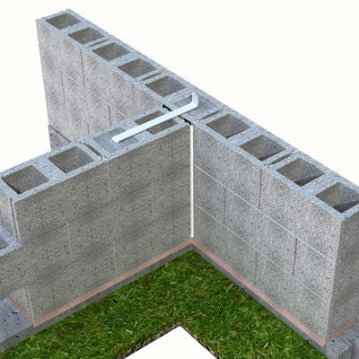
With respect to masonry walls, rigidity will always impacts the capacity of the wall to resist lateral loads, hence the effect of support conditions must be taken into account. Annex F of BS EN 1996-1-1 contains figures showing typical restraint conditions for masonry wall. This would be referred to when determining the bending moment capacity of the wall.
Material Properties
Material properties depends on the type of masonry material and the material used for the joints. Typical values of material partial factors, shear and flexural strength may be found in the UK National Annex to BS EN 1996-1-1. Specifically, Table NA.1 provides values of partial factors γM, Table NA.2 provides the definition of mortar types and Table NA.5 describes the shear strength of masonry. Table NA.6 defines the values of flexural strength of masonry depending on its mode of failure.
Flexural Design
As stated in one of the preceding sections, designing a laterally loaded wall requires a good appreciation of its geometry, support conditions and material properties. These three parameters influences the flexural capacity of the wall. When designing a laterally loaded masonry wall against flexure, the following conditions must be satisfied.
{ M }_{ Ed,1 }\le { M }_{ Rd,1 }----(1){ M }_{ Ed,2 }\le { M }_{ Rd,2 }----(2)Where MEd,1 & MEd,2 are the applied bending moment parallel & perpendicular to the wall bed respectively and while MRd,1 & MRd,2 are the bending moment capacities parallel and perpendicular to the bed joint respectively.
Applied Bending Moment
The applied bending moment parallel to wall bed is determined from the following equation:
{ M }_{ Ed,1 }=\mu{\alpha}_{2}{W}_{Ed}{l}^{2}----(3)The applied bending moment perpendicular to wall bed is determined from the following equation:
{ M }_{ Ed,2 }={\alpha}_{2}{W}_{Ed}{l}^{2}----(4)Where: u is defined as the orthogonal ratio; alpha2 is the bending moment coefficient determined using the charts presented in Annex E of BS EN 1996-1-1; WEd is the design lateral load applied on the wall and l is the length of the wall.
The orthogonal ratio is obtained from the following equation.
\mu=\frac{{f}_{xk1}}{{f}_{xk2}}----(5)Where: fxk1 is flexural strength of masonry based on failure that is parallel to bed joints based. Similarly, the value of fxk2 is the flexural strength of masonry based on failure that is perpendicular to bed joints. Both factors can be determined from table NA.6 of UK-NA to BS EN 1996-1-1.
Bending Moment Capacity
The bending moment capacity parallel to bed joint is determined from the following equation.
{ M }_{ Rd,1 }=\left(\frac{{f}_{xk1}}{{\gamma}{M}}+{\sigma}_{d}\right)Z----(6)The bending moment capacity perpendicular to bed joint is determined from the following equation.
{ M }_{ Rd,2 }=\left(\frac{{f}_{xk2}}{{\gamma}{M}}\right)Z----(7)Where: σd is the applied compressive stress (N/mm2) and Z is the elastic modulus of the wall.
Shear Design
For masonry walls, a design against shear means that the following equation must be satisfied.
{V}_{Ed}\le{V}_{Rd}----(8)Where: VEd is the applied shear force and VRd is the shear capacity of the wall.
The wall’s shear capacity can be estimated from the following equation.
V_{Rd}={f}_{vd}t{l}_{c}----(9)Where: fvd is the shear strength of the wall drawn from table NA.5 in the UK National Annex of BS EN 1996-1-1; t is the thickness of the wall lc is the length of wall under compression.
Steps in Designing a Laterally Loaded Masonry Wall
- Determine the design values of the applied lateral actions
- Verify the wall dimensions with respect to slenderness and geometry
- Determine the applied bending moments and bending moment capacities and ensure that the attached conditions are satisfied
- Determine the applied shear force and shear capacity and ensure that the attached condition is satisfied.
Worked Example
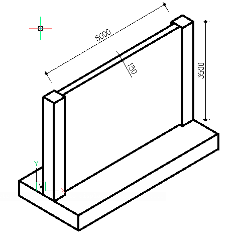
A 3.5m tall wall, spanning between piers at 5m centres has to withstand a design wind action of 1.5kN/m2. It is founded on a mass concrete strip footing and is bonded to the piers, forming a continuous connection. The top of the wall has no lateral support and is free to move. The wall is to be made from 150mm thick masonry blocks with moisture absorption of 10% and a Class M2 mortar that is 10mm thick. Determine if this block can withstand the design wind action.
Serviceability Verification
\frac { l }{ t } =\frac { 5000 }{ 150 } =33.3\quad\frac { h }{ t } =\frac { 3500 }{ 150 } =23.3
Checking against Fig. F3 of BS EN 1996-1-1 wall geometry is satisfactory.
Flexural design
Applied bending moment
\frac { h }{ l } =\frac { 3500 }{ 5000 } =0.7From Table NA.6 fxk1 = 0.2& fxk1 = 0.6
\mu=\frac{{f}_{xk1}}{{f}_{xk2}}=\frac { 0.2 }{ 0.6 } =0.33{\alpha}_{2}=0.038Applied bending moment parallel to wall bed:
{ M }_{ Ed,1 }=\mu{\alpha}_{2}{W}_{Ed}{l}^{2} =0.33\times0.038\times1.5\times{3.5}^{2}=0.23kN.mApplied bending moment perpendicular to wall bed:
{ M }_{ Ed,1 }={\alpha}_{2}{W}_{Ed}{l}^{2} =0.038\times1.5\times{3.5}^{2}=0.70kN.mBending moment capacities
{ \sigma }_{ d }=\frac { 1\times 3.5\times 20\times { 10 }^{ 3 } }{ { 10 }^{ 6 } } =0.07kN/{ m }^{ 2 } Z=\frac { { bh }^{ 2 } }{ 6 } =\frac { { 10 }^{ 3 }\times { 150 }^{ 3 } }{ 6 } =3750\times { 10 }^{ 3 }{ mm }^{ 4 }The bending moment capacity parallel to bed joint:
{ M }_{ Rd,1 }=\left( \frac { { f }_{ xk1 } }{ { \gamma }{ M } } +{ \sigma }_{ d } \right) Z=\left( \frac { 0.2 }{ 2.7 } +0.07 \right) 3750\times { 10 }^{ 3 }=0.54kN.mThe bending moment capacity perpendicular to bed joint:
{ M }_{ Rd,2 }=\left( \frac { { f }_{ xk2 } }{ { \gamma }{ M } } \right) Z=\left( \frac { 0.6 }{ 2.7 } \right) 3750\times { 10 }^{ 3 }=0.83kN.mFlexural Verification
{ M }_{ Ed,1 }(0.23kN.m)\le { M }_{ Rd,1 }(0.54kN.m) o.k{ M }_{ Ed,2 }(0.70kN.m)\le { M }_{ Rd,2 }(0.83kN.m)o.kShear Design
Applied shear force
{ V }_{ Ed }=1.5\times 3.5\times 5.0=26.3kNShear Capacity
{ f }_{ v/k }={ f }_{ vk0 }+0.4{ \sigma }_{ d }\\ =0.1+0.4(0.07)=0.13N/{ mm }^{ 2 }{ V }_{ Rd }={ f }_{ vd }t{ l }_{ c }\\ =0.13\times 150\times \left( 3500+2(5000) \right) =243kN{V}_{Ed}(26.3kN)\le{V}_{Rd}(243kN)o.k150mm masonry wall is satisfactory.
Also see: Design & Detailing of Lintels in Masonry Walls
Sources & Citation
- The Institution of Structural Engineers (2008) Manual for the design of plain masonry in building structures to Eurocode 6 London: The Institution of Structural Engineers
- Designing a Laterally Loaded Masonry Wall, The Structural Engineer, 93 (06), pp. 27–29
- BS EN 1996-1-1 Eurocode 6: Design of Masonry Structures – Part 1-1: General Rules for Buildings
- BS EN 1996-1-1 UK National Annex to Eurocode 6: Design of Masonry Structures – Part 1-1: General Rules for Buildings.
Thank You!