This article describes how to detail a concrete column with respect to geometry, concrete cover, minimum and maximum area of longitudinal reinforcement, size and spacing longitudinal and transverse bars etc.
Accurate detailing has an important role in the procurement and durability of reinforced concrete structures. Detailing, which is the process of presenting the result of the design process into drawings that can be utilized for implementation consists of a set of rules that not only ensures that a design is implemented in accordance with the design intent but also ensures that a design is constructible.
In the context of concrete columns, Eurocode 2 specifies some detailing rules that must be followed to ensure structural integrity, durability and overall safety of a structure. It specifies the minimum and maximum reinforcement ratios, spacing of reinforcement, anchorage and lap lengths, as well as the cover requirements for different environmental exposure classes. It also considers the distribution of reinforcement along the length of the column, including potential variations in bending moments and axial loads.
This article describes how to detail a concrete column with respect to geometry, concrete cover, minimum and maximum area of longitudinal reinforcement, size and spacing longitudinal and transverse bars etc.
Detailing Principles
Eurocode 2 recognizes various column types, such as rectangular, circular, and other shapes. The code provides guidance on the minimum and maximum dimensions for different types of columns, as well as detailing requirements for features like openings and projections. The geometric parameters of the columns, such as slenderness ratios, also play a crucial role in determining the detailing requirements.
It is important however, to state that this article does not apply to concrete walls. Walls within the context of the Eurocode is defined as having breath/thickness ratio greater than 4.
Within Eurocode 2, the requirements for detailing concrete columns are outlined in Clause 9.5 of BS EN 1992-1-1:2004. This clause describes material strength, cover, minimum and maximum area of main reinforcing steel, bar spacing and so on. These requirements are presented in the subsequent section.
Concrete Grade
Unless extra precautions are taken to withstand the bursting forces, care should be taken to ensure that the design strength of concrete required in a column does not exceed 1.4 times that in the slab or beam intersecting it. Concrete grades for columns are typically within the range of 20/25 -30/35 MPa (cylinder strength/cube strength).
Nominal Cover
Adequate cover to reinforcement is required in reinforced concrete structures to ensure durability and fire resistance. Within Eurocode 2, this is covered in Clause 4.4. For concrete columns, the nominal cover will mostly govern. This is defined as:
- Internal use 30mm + Δcdev (Concrete inside buildings with low air humidity, XC1)
- External use 35mm + Δcdev (Corrosion induced by carbonation, XC3)
Where, Δcdev = 5-10mm
For bundled bars, the cover is taken as equivalent to the bar size.
With respect to cover, Clause 4.5.2 of Eurocode 2-1-1 further states that where nominal cover exceeds 40mm, there is a danger of concrete spalling during fire. Hence, surface reinforcement in the form of mesh should be provided. The mesh should have a spacing not greater than 100mm, and a diameter not less than 4mm.
Longitudinal Bars
With respect to the main or vertical reinforcement, Clause 9.5 talks about the minimum/maximum area of steel that is allowed in a concrete column, bar sizing, spacing of bars, anchorage and lapping of bars. Each of these are explained under separate headings.
Minimum Area of Reinforcement
According to Clause 9.5.2, the minimum area of steel allowed in a concrete column shall be the greater of the following:
\frac{0.1N_{Ed}}{f_{yd}} \ge 0.02A_cWhere: NEd is the design axial load on the column; fyd is the design yield strength of the reinforcement; and Ac is the cross-sectional area of concrete.
Maximum Area of Reinforcement
The maximum area of steel should not exceed 0.04Ac unless it can be otherwise shown that any resulting congestion of reinforcement does not hinder the ease of construction. At laps, this value can be increased to 0.08Ac. Mechanical splices, such as couplers can be considered, where congestion is poised to be a problem.
Bar Sizing
The recommended minimum bar diameter for concrete columns is 16mm. However, for very small column sections, less than 200mm, smaller bar size may be used.
For as long as other detailing rules are not violated, there is no restriction on the maximum bar size that can be provided.
As for the number of bars that should be provided in a column, there is again no restriction on the maximum value, provided other rules are not violated. However, there is a recommendation on the minimum values which depends on the column cross-sections.
- For rectangular columns, a minimum of 4 bars is recommended.
- For circular columns, a minimum of 6 bars is recommended
- For columns having a polygonal cross-section, at least one bar should be placed at a corner.
Bar Spacing
A minimum spacing of 75mm is allowed for main bars if the bar size is less than 40mm. But, if the main bars are greater than 40mm, a minimum spacing of 100mm should be used.
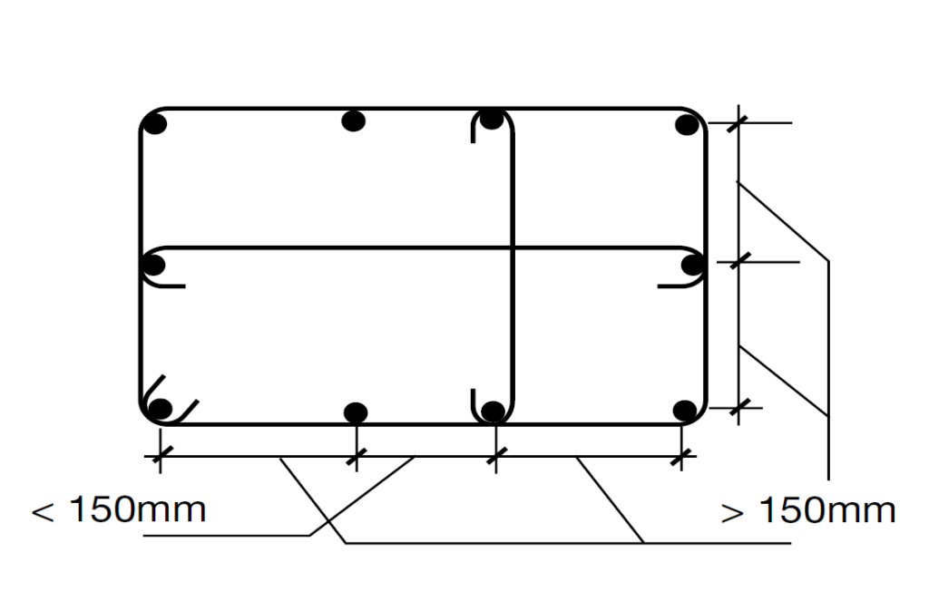
A maximum value of 300mm is permitted for bar spacing as long as every bar is within 150mm of a constrained bar.
Anchorage & Lapping of Bars
Anchorage and lapping are essential in concrete columns to ensure load transfer between bars. Estimating anchorage and lapping lengths depends on a lot of factors which cannot be covered in this article. However, there are rules of thumb that have been developed to simplify the process of estimating anchorage and lapping. This is usually expressed as a factor of the bar diameter.
For 500 Grade steel, Figure 1 gives typical anchorage and lap lengths for columns, depending on the concrete grade.

Links
Clause 6.5.2 further describes the detailing rules for traverse reinforcement provided in columns. These rules cover minimum bar size and spacing of the links.
Bar Size
According to Clause 6.5.2, the column link size shall be larger of one-quarter the maximum longitudinal bar size or 8 mm (the minimum of 6 mm specified in EC2 may apply to columns with extremely small diameters, less than 200 mm).
For the purpose of computing link size, where bundled bars are used, the bundled bars should be represented by a single bar. This single bar should have an equivalent size as to give the same cross-sectional area as the bundle.
With respect to the number of links, an overall link is normally provided together with additional restraining links as may be required. For instance, if all longitudinal bars in the compression zone are fully restrained by the overall link or all main bars are within 150mm of a restrained bar, no other links will be required (See Figure 2). Otherwise, additional links should always be provided in order to satisfy this requirement.
The above rule, however, does not apply to circular columns. Additional links are not required. Only the overall link is provided.
Bar Spacing
The spacing of links in concrete columns shall be the lesser of the following:
- 20 times the diameter of the longitudinal bars
- The lesser dimension of the column
- 400mm
These values are however, to be lessen by 0.6 above and below the beam/slab the column supports, within a distance equal to the larger dimension of the column cross-section. Where the direction of the longitudinal bar changes (e.g. at laps), the spacing of links should be calculated. The spacing of links should ensure that there is a link close to the cranking positions of the main bars. These effects may be ignored if the change in direction is 1 in 12 or less.
Bursting at Laps
Where a change in column cross-section occurs, particularly in edge or corner locations, there is a tendency for bursting at the location of lapping. Hence, providing additional links by reducing the spacings may be necessary to provide adequate restraints.
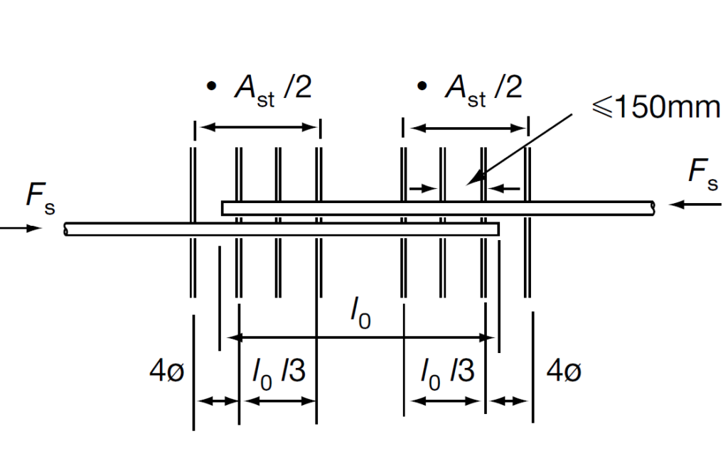
Where the diameter of the longitudinal bars is greater than 20mm, the links required to resist the bursting forces in the lapping zone should have a total area SAst, of not less than the area As of one lapped bar (SAst > 1.0As). These links should be positioned at the outer sections of the lap as shown in Figure 3.
Detailing Information
Having considered the detailing principles, a drawing is prepared showing the column detailing information. This detailing information should clearly define the following:
- Outline drawings which show clearly what happens to the column above the lift being considered.
- Kicker height if other than 75mm.
- Concrete grade and aggregate size (standard 30/37MPa and 20mm).
- Nominal cover to all reinforcement (standard 35mm internal, 40mm external). Supplementary mesh reinforcement if required.
- A simple sketch of cross-section of column showing the longitudinal reinforcement in each face of the column, i.e. number and position of bars; type of reinforcement and bond characteristics (standard H); diameter of bars; lap length if other than normal compression laps the linking reinforcement; type of reinforcement (standard H); diameter of links & spacing; pattern of links (if special)
- Instructions for lapping of bunched bars if required.
- Special instructions for links within depth of slab or beam.
- If a mechanical or special method of splicing bars is required this must be shown in a sketch, otherwise the method given in the Model Details will be assumed.
- Special instructions and sketches should be given where services are provided within the column.
- Details of insertions, e.g. conduit, cable ducting, cladding fixings, etc., should be given where the placing of reinforcement is affected.
Worked Example
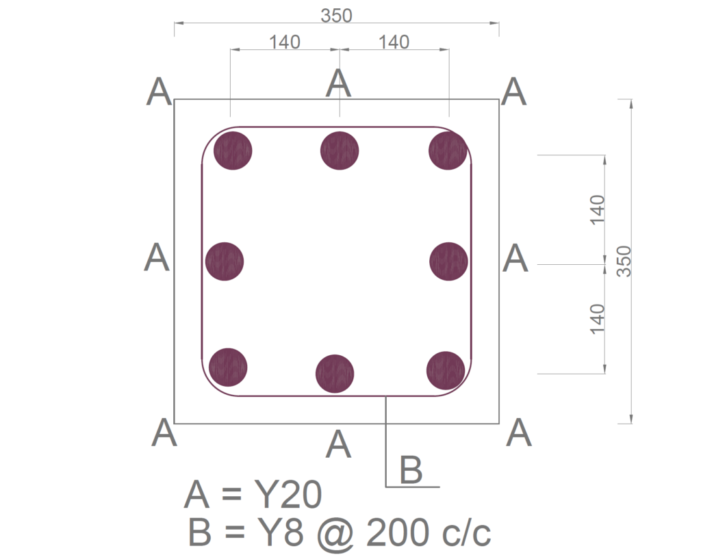
A 3.5m high 350 x 350mm concrete column supports an axial load of 2100kN. Assuming the area of steel required to support this axial load and the accompanying bending moments is 2130mm2. Detail the column completely, assuming a 1hour fire rating, C25/30 concrete and 500Mpa reinforcing steel bars.
Longitudinal Bars
Minimum & Maximum Area of Steel
A_{s,max}\ge A_{s,req} \ge A_{s,min}{ A }_{ s,min }=\frac { 0.10{ N }_{ Ed } }{ 0.87{ f }_{ yk}} \ge0.002A_c=\frac{0.1\times 2100\times 10^3}{0.87\times 500} \ge 0.002\times 350^2=482.8mm^2
A_{s,max}=0.04A_c=0.04\times350^2=4900mm^2Since the area of steel required is greater than the minimum area of steel required and less than the maximum area of steel that can be provided, we can quantify the reinforcement using the area of steel required.
Assuming 20mm Bars; number of bars required:
n=\frac{A_{s,req}}{314}=\frac{2130}{314} =6.78Use 8Y20mm bars (As, prov = 2512mm2)
Anchorage & Laps
l_{anc}=36\phi=36\times20 =720mml_{lap}=54\phi =54\times20=1080mmContainment Links
Bar Size
{ \phi }_{ required }=0.25{ \phi }_{ bar } >8mm\\=0.25\times 20=6mm\quad Use\quad Y8Spacing
s = 20d | 350mm|400mm
s =20\times20=400mm <400mm<350mm
At below and above the beam, spacing is to be reduced by 0.6. Therefore, 0.6 x 350 = 210mm
Use Y8 @ 200mm c/c
See: Designing a Concrete Columns to Eurocode 2
Detailing Resume
Sources & Citations
- The Institution of Structural Engineers (2006) Standard Methods of Detailing Structural Concrete- A manual for best practice (Third Edition) London: The Institution of Structural Engineers.