In this article, we explore the principles and best practices of structural concrete detailing. We discuss different types of drawings, essential title block components, reinforcement placement, and detailing methods
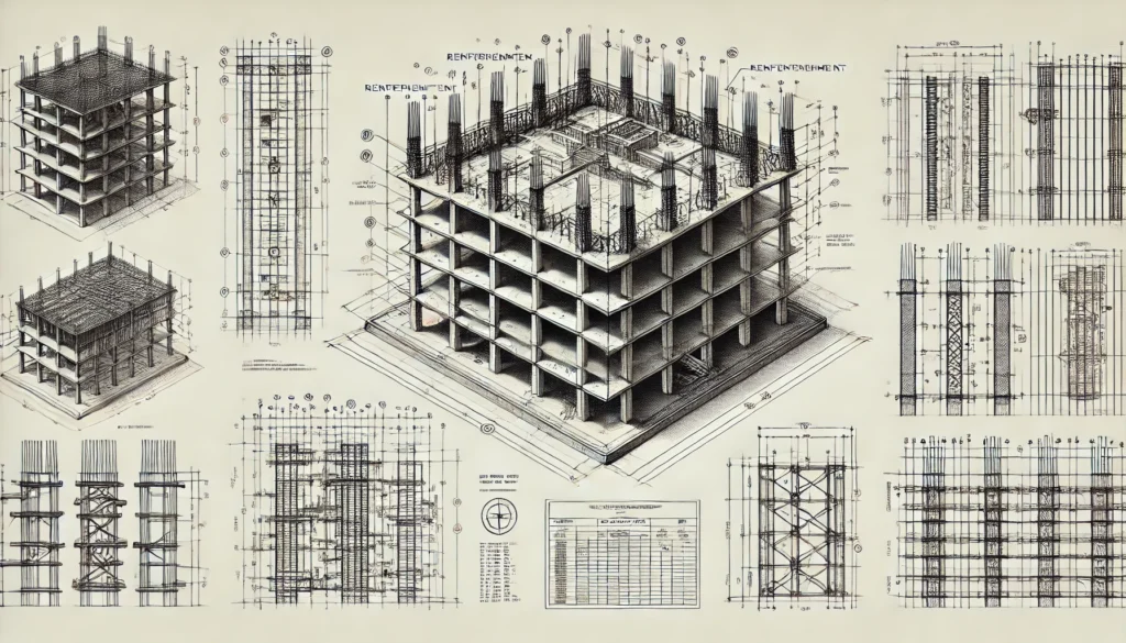
Structural concrete detailing is the foundation of every well-designed concrete structure. It transforms engineering concepts into precise construction drawings that guide builders, ensuring accuracy, safety, and efficiency. Every detail—from reinforcement placement to column dimensions—must be meticulously documented to maintain the structural integrity of a building. Without clear and well-organized drawings, errors can occur on-site, leading to costly rework, project delays, or even structural failures.
The role of detailing extends beyond simple technical drafting. It serves as a communication tool between structural engineers, architects, contractors, and fabricators. Proper detailing positions reinforcement bars correctly, aligns beams and slabs with load paths, and strategically places construction joints to prevent cracks. Engineers follow standardized detailing methods that comply with national and international building codes to maintain consistency across projects.
In this article, we explore the principles and best practices of structural concrete detailing. We discuss different types of drawings, essential title block components, reinforcement placement, and detailing methods for key structural elements such as foundations, beams, slabs, and columns. Through clear explanations and references to standard guidelines, this article provides a comprehensive understanding of how precise detailing contributes to safe and durable concrete structures.
Types of Structural Drawings
Concrete detailing consists of different drawing types, each with a unique function in the construction process.
Structural Drawings
Structural drawings serve as blueprints for constructing concrete elements. They define the overall structure, including its shape, position, and arrangement. These drawings typically include general arrangement plans, sectional views, and elevations. They also specify levels, dimensions, and positions of structural components such as columns, beams, and slabs.
In addition to layout information, structural drawings indicate locations for holes, chases, and fixings. They may include specification notes related to material quality, concrete finishes, and load-bearing requirements. These drawings help contractors set out and construct structural elements according to design specifications.
Reinforcement Drawings
Reinforcement drawings focus on detailing the steel reinforcements embedded within the concrete. These drawings provide instructions for placing and arranging steel bars to ensure the structure resists applied forces. They include bar shapes, lengths, bending schedules, and overlap requirements. Proper reinforcement detailing prevents structural failure by ensuring that steel reinforcements align with load distribution requirements.
The drawings also show clearances for holes and embedded fixtures, which prevent interference with reinforcement placement. Steel fixers rely on reinforcement drawings to install bars correctly before concrete pouring begins. A well-detailed reinforcement drawing ensures efficient on-site execution, minimizing errors and material wastage.
Standard Details
Standard details consist of commonly used reinforcement patterns, concrete profiles, and fixing arrangements. Engineers develop these details for repetitive structural elements, ensuring consistency across multiple projects. Using standard details speeds up the design process while maintaining quality and uniformity. When applying standard details, engineers fully detail them and ensure their suitability for every location where they appear.
Record Drawings
After construction, record drawings document any modifications made during execution. These drawings reflect the final built structure, capturing changes to reinforcement layouts, material specifications, or structural dimensions. They form part of the project’s safety documentation and assist in future maintenance, renovations, or structural assessments.
Best Practices for Structural Concrete Detailing
Effective detailing follows essential guidelines that enhance clarity, accuracy, and efficiency.
Drawing Format and Clarity
Clarity is essential in structural detailing. Drawings should be large enough to show details without congestion. Engineers often use A1-sized sheets for general arrangement drawings, while A3 and A4 sizes work well for detailed views. Proper spacing and organization of information improve readability. Consistent use of standard fonts, line thicknesses, and dimensioning styles further enhances clarity.
Consistent Notation and Symbols
Standard abbreviations and symbols help ensure quick interpretation of drawings. Engineers use common abbreviations such as “RC” for reinforced concrete, “FFL” for finished floor level, and “SSL” for structural slab level. Maintaining a consistent system of notation reduces confusion and misinterpretation.
Grid Systems and Reference Lines
A structured grid system provides a clear reference for locating structural elements. Grid lines are labeled numerically in one direction and alphabetically in the other. This system ensures that every structural component has a fixed reference point, making coordination easier between design drawings and site execution.
Dimensioning and Levels
Precise dimensions are crucial in concrete detailing. General arrangement drawings indicate setting-out dimensions for positioning structural elements. Reinforcement drawings provide only the necessary dimensions for correct steel placement. Levels, such as structural slab levels, foundation depths, and finished floor levels, must be clearly marked to avoid misinterpretation.
Reinforcement Placement
Reinforcement detailing must ensure that concrete structures achieve their required strength. Detailing should specify reinforcement spacing, overlaps, and anchorage lengths. The position of links and stirrups should also be shown accurately. Proper reinforcement placement enhances durability and ensures the structure can bear loads effectively.
Title Block and Project Identification
A well-structured title block provides essential details for tracking and managing construction drawings. It includes the office project number, a unique identifier assigned by the engineering firm, and the project title, which clearly states the type and location of the structure. Each drawing has a drawing number with a revision suffix (e.g., DRG-001 Rev A) to track updates and ensure only the latest version is used on-site. The drawing title briefly describes the drawing’s content, such as “Foundation Layout” or “Beam Reinforcement Details”.
The office of origin refers to the firm responsible for creating the drawing, ensuring accountability. The scale defines the drawing’s proportion to the actual structure (e.g., 1:100, 1:50), ensuring precise measurements, especially when resized or microfilmed, as recommended in BS 5536. The drawn by and checked by sections record the drafter and the reviewing engineer to maintain quality control. Finally, the date of drawing marks when it was created or last revised, ensuring teams reference the most current version. A well-organized title block enhances clarity, reduces errors, and ensures smooth communication between engineers, contractors, and site teams.
Structural Elements and Their Detailing
Foundations
Foundation detailing specifies the position, dimensions, and reinforcement layout of the foundation system. The drawings indicate excavation depths and the level at which concrete foundations begin. For projects involving piled foundations, the piling plan marks pile locations, load capacities, and cut-off levels. Foundation plans must also specify the allowable bearing pressure of the soil.
See: A Guide to Detailing Foundations to Eurocode
Columns
Columns transfer loads from upper floors to the foundation. Detailing includes cross-sectional dimensions, reinforcement layouts, and splice lengths for connecting column segments. Column positions within the grid system must be clearly marked. If the column size changes between floors, the drawings should indicate these variations.
See: Detailing a Concrete Column to Eurocode 2 | Worked Example
Beams
Beam detailing ensures that beams can resist bending and shear forces. Drawings specify reinforcement at the top and bottom of the beam, along with shear links spaced at appropriate intervals. Downstand beams and upstand beams should be labeled clearly, with their soffit levels indicated. Beam elevations and sectional views help clarify reinforcement placement.
Slabs
Slabs distribute loads across structural elements and require accurate detailing. Different types of slabs include one-way slabs that span in one direction, two-way slabs that span in two perpendicular directions, and cantilever slabs that project beyond supports. Detailing must indicate the span direction, thickness, and reinforcement layout. In cases where slabs have multiple reinforcement layers, separate drawings should be provided for each layer.
See: Detailing of Concrete Slabs to Eurocode 2
Walls
Reinforced concrete walls need proper detailing to ensure stability. Drawings must specify wall thickness, horizontal and vertical reinforcement spacing, and the location of door and window openings. Load-bearing walls require additional reinforcement to resist vertical and lateral forces. If a wall size differs between floors, this should be clearly marked on the drawings.
Stairs
Stair detailing includes tread dimensions, riser heights, and landing levels. Drawings must indicate the structural waist thickness, nosing details, and fixing points for railings. In cases where floor finishes vary, adjustments may be necessary to ensure uniform riser heights. Proper stair detailing ensures safety and compliance with building regulations.
Special Considerations in Concrete Detailing
Construction Joints
Construction joints should be positioned at points of minimal stress. Drawings must specify joint locations, types, and reinforcement details to maintain structural integrity.
Tolerances and Site Adjustments
Allowable tolerances for structural elements should be noted on drawings. If site adjustments occur, they must be documented to ensure consistency between design and execution.
Coordination with Other Trades
Structural drawings must align with architectural, mechanical, and electrical layouts. Clash detection prevents conflicts between reinforcement placements and service installations such as plumbing and electrical conduits.
Conclusion
Concrete detailing is a vital aspect of structural engineering, ensuring the successful execution of construction projects. Accurate and well-structured drawings prevent errors, improve material efficiency, and enhance communication among engineers, architects, and contractors. By following best practices, structural engineers can create durable, safe, and cost-effective concrete structures.
The key to successful detailing lies in precision, clarity, and adherence to established standards. With proper reinforcement placement, clear notation, and efficient coordination, well-detailed concrete structures can withstand loads effectively and remain resilient for years to come.
See: How to Prepare Structural Design Report Calculations
Sources & Citations
- Institution of Structural Engineers (IStructE) & The Concrete Society – Standard Method of Detailing Structural Concrete.
- British Standards Institution (BSI) – BS 5536: Guide for Scale and Reproduction of Engineering Drawings.
- BS 1192: Construction Drawing Practice – Code of Practice for Production of Construction Drawings.