This article explores the design and construction of ground bearing slab using steel fibre reinforcement in place of traditional steel
Ground-bearing slabs permeate a multitude of structures, including commercial offices, residences, schools, and hospitals. However, they predominantly appear in large warehouses and out-of-town shopping complexes. These buildings frequently house tall storage racks that exert concentrated point loads on the slab. Ground bearing slabs are laid directly onto a sub-base material, which deflects and heaves under load. These slabs, acting as flexural elements, distribute the load with the founding material beneath them. Thus, they cannot be classified as rafts due to their insufficient stiffness, making soil-structure interaction a crucial consideration.
The design of ground-bearing reinforced concrete floors has significantly changed in recent times, with the major development being the increasingly common adoption of steel fibre reinforcement. This was briefly highlighted in the previous article (Design and Detailing of Ground Bearing Slabs), which introduced ground-bearing slabs with respect to their construction and detailing. This article describes how steel fibre reinforced concrete ground-bearing slabs are designed in detail. This is a relatively recent innovation that continues to evolve. As such, this article aims to motivate the design and development of steel fibre reinforced ground-bearing slabs, based on the most up-to-date information available at the time of writing.
Also borrowing from the commonality of the use of ground bearing slabs in warehouses and similar buildings, this article chiefly focuses on the design of slabs that are subject to such loading conditions. The concentrated point loads from storage racks can induce punching shear failure in the slab, as well as the initiation of cracks within the slab as it deforms. Plant vehicles such as forklifts place dynamic point loads within discrete rectilinear shaped areas where they traverse.
Founding Material
A very important consideration in the design of ground bearing material is the founding material. The founding material is the soil beneath, that supports the slab.
The modulus of subgrade reaction (k) is the key factor of the founding material relevant to ground-bearing slabs. Engineers typically determine these using results from a plate bearing test on the soil, following BS EN 1997-2 standards. If conducting such a test is not possible, they can estimate k from other known soil properties, though this method is not recommended due to potential inaccuracies. Similarly, they should avoid deriving k from the Californian Bearing Ratio (CBR) of the soil.
The value of k usually ranges from 0.03 to 0.08 N/mm²/mm. Engineers should seek advice on its magnitude from a qualified and experienced geotechnical engineer, and they can find further details in Chapter 5 of TR34: Concrete Industrial Ground Floors (4th ed.). Ground investigations should provide all relevant data to aid in designing the ground-bearing slab, particularly regarding potential long-term settlement under imposed area loads, line loads, and concentrated loads.
Above the founding material lies a sub-base, which must be at least 150 mm thick and composed of well-compacted Type 1 and 2 granular materials, as defined in the Specification for Highway Works, Series 800, Road Pavements, published by the UK’s Highways Agency.
Fabric or Steel Fibre as Reinforcement
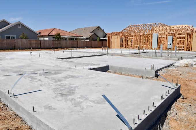
In recent years, builders and engineers have increasingly adopted steel fibre reinforcement to enhance the flexural tension capacity of ground-bearing slabs. This method streamlines the construction process significantly. Instead of the labour-intensive task of installing fabric reinforcement, workers simply mix metal steel fibres into the concrete (Figure 1). This approach not only simplifies installation but also accelerates project timelines, reducing labour costs and minimizing potential errors associated with traditional reinforcement techniques.
Besides, steel fibre reinforcement offers additional benefits beyond ease of installation. It provides uniform reinforcement throughout the concrete matrix, enhancing the durability and longevity of the slabs. The dispersed fibres help control cracking and improve the overall load-bearing capacity of the concrete, making it particularly suitable for high-stress environments like warehouses and industrial floors.
Structural Properties of Steel Fibre Reinforced Concrete
Including steel fibre reinforcement in concrete enhances its tension capacity across the entire cross-section. The form and distribution of the steel fibres throughout the concrete mix affect their effectiveness in providing this tension capacity. To account for these factors, the method for determining the structural properties of steel fibre reinforced concrete considers these variables, which depend on the manufacturing process of the steel fibres and their integration into the concrete.
For steel fibres to be effective, they must be sufficiently included in the concrete mix to achieve a residual flexural strength (fR) greater than that of unreinforced concrete. Similar to traditional reinforcement, the ultimate strength model assumes that the concrete cracks before the steel fibres begin to function as a reinforcing element. Consequently, the concrete’s flexural strength depends on the magnitude of the crack mouth opening displacement (CMOD) when the concrete deflects under load.
EN 14889 requires steel fibre manufacturers to specify the quantity needed in the concrete to achieve the desired flexural strength, which depends on the concrete’s CMOD value.
Flexural Capacity
Ground bearing concrete slabs have two flexural capacities. One based on their reinforced properties Mu and the other on their unreinforced properties Mun.
Flexural Capacity of Unreinforced Concrete
The bending capacity of an unreinforced concrete slab of 1m width is defined as:
M_{un}=f_{ctd,fl}(\frac{h^2}{6})Where:
h is the overall depth of the slab fctd,fl is the flexural strength of unreinforced concrete as defined in Clause 3.1.8 of BS EN 1992-1-1. Here fctd,fl is defined as:
f_{ctd,fl}=f_{ctm}\times(1.6-\frac{h}{1000})/\gamma_m \ge \frac{f_{ctm}}{\gamma_m}Where:
- fctm is the mean axial tensile strength of concrete that is drawn from Table 3.1 of BS EN 1992-1-1 and partially reproduced in Table 1
- m is the material factor of concrete, which is 1.5 as stated in Clause 2.4.2.4 of BS EN1992-1-1
| Concrete strength class | C25/30 | C28/35 | C30/37 | C32/40 | C35/45 | C40/50 |
| fctm (N/mm2) | 2.6 | 2.8 | 2.9 | 3.0 | 3.2 | 3.5 |
Flexural Capacity of Steel Fibre Reinforced Concrete
The bending capacity is based on the residual flexural tensile strength, which can only be determined through laboratory testing. This testing involves a series of experiments on a dozen concrete beams made from steel fibre reinforced concrete that matches the mix properties intended for a project. These beams are tested according to BS EN 14651 (the test for notched beams). The impact of steel fibre reinforcement on concrete is derived using the method described in BS EN 14845. The results of these tests are used to calculate the bending moment capacity per metre width of the steel fibre reinforced concrete (fR) using the following formula:
f_R=\frac{3F_Rl}{2bh^2_{sp}}where:
- fR is the applied load on the beam
- l is the span of the beam
- b is the width of the beam
- hsp is the depth of the beam
This calculation is performed four times using a batch of three test samples, and the mean value of the four flexural strength results is used to design the concrete element. These four values are fR,1, fR,2, fR,3, and fR,4. Two critical values, fR,1 (ranging from 1-6 N/mm²) and fR,4 (ranging from 0-4 N/mm²), are used to determine the bending capacity of steel fibre reinforced concrete. More details on this method can be found in the Rilem document TC 162-TDF.
From this test data, the bending capacity of the reinforced concrete (Mu) can be calculated. This can be done through a rigorous method requiring significant iteration, or a simplified yet conservative method based on key assumptions about the concrete’s behaviour in bending. These assumptions are:
- Failure occurs when the compressive strain within the concrete reaches 0.0035.
- As the concrete element approaches its ultimate bending moment capacity, its maximum tensile and compressive strains are reached. Due to the higher compressive strength of the concrete compared to the tensile strength of the steel fibres, equilibrium is not achieved because the compressive force in the concrete exceeds the tensile force in the steel fibres.
- The neutral axis of the concrete element is a constant multiple of its depth.
Chapter 6.3.5 of TR34 describes how the following equation can be derived to calculate the bending capacity of steel fibre reinforced concrete slabs based on 1m width:
M_u=\frac{h^2}{\gamma_m}(0.29\sigma_{r4}+0.16\sigma_{r1})Where:
- h is the overall depth of the concrete element (mm)
- σr4 is the stress corresponding to a residual flexural tensile strength of 0.45fR,4
- σr1 is the stress corresponding to a residual flexural tensile strength of 0.37fR,1
Shear Capacity
Steel fibre reinforcement does not contribute to enhancing the shear capacity (vf) of the concrete. The shear capacity is assumed to be 1.5% of its flexural strength capacity. However, due to insufficient empirical data supporting this value, it is reduced by 50% as follows:
\nu_f=\frac{0.015(f_{R1}+f_{R2}+f_{R3}+f_{R4})}{2}Where:
- fR,1-4 are the four residual flexural tensile strength values drawn from test data.
Applied Actions
A ground bearing slab may face three main types of applied load: concentrated point loads from storage racks and vehicles, line loads from partition walls, and imposed area loads. The most critical concerns are concentrated point loads and line loads, as they impose the highest level of bending stress on the slab. Additionally, thermal stresses represent another challenge, which can be managed by incorporating joints within the slab or designing it to withstand thermally induced movement.
Single concentrated point loads
Single concentrated point loads generate both positive and negative bending moments due to the deflected shape of the slab under load. The steel fibre reinforced slab’s ability to withstand the concentrated point load is determined based on the slab’s bending strength. This strength is calculated from the positive and negative bending moment capacities of the slab (Figure 2).
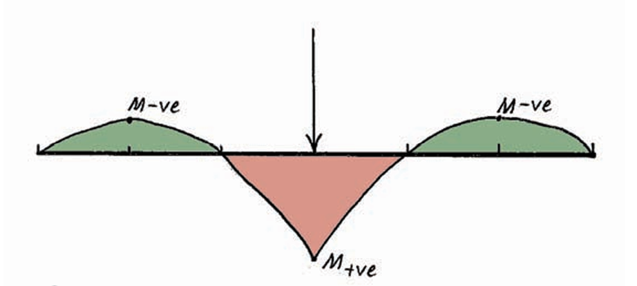
The positive bending moments (M+ve) stem from the ultimate bending moment capacity of steel fibre reinforced concrete (Mu) and are established using the cracked concrete model. The negative bending moments (M-ve) are derived from the unreinforced concrete moment bending capacity (Mun), assuming a crack-free surface. Consequently, the positive bending moment remains static in magnitude, and any increase in applied actions leads to moment redistribution and an increase in the negative bending moment. This progression continues under increasing load until cracking occurs in the top surface, some distance away from the point load location.
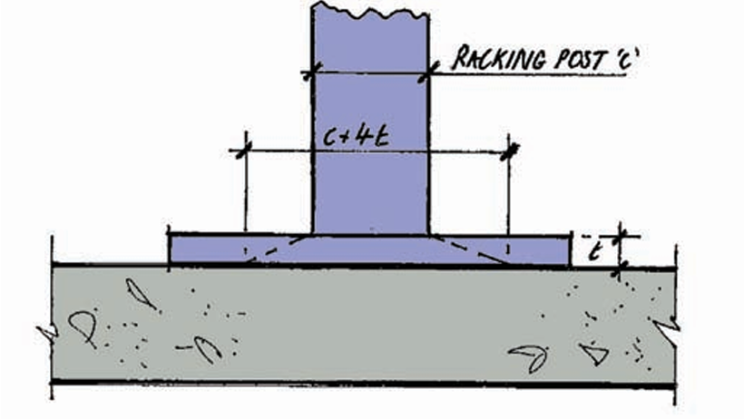
The location of applied loads, relative to the edge of the slab and their proximity to other loads, also influences the applied bending moments. Two key variables must be calculated before assessing the effects: the radius of the contact area of the vertical element applying the force (a), and the radius of relative stiffness of the slab (l) (Figure 4). From figure 4, the value of a can be calculated as follows:
\alpha_{max}=\sqrt \frac{(c+4t)^2}{\pi}Where:
- c is the width of the racking post
- t is the thickness of the baseplate.
When precise baseplate dimensions are unknown, it can be assumed to be a 100mm × 100mm area. The spread of load in the baseplate can be taken as 1:2.
The relative stiffness radius is based on the likely crack pattern that develops, as a point load is applied to the slab. It is derived using the following equation:
l=(\frac{E_{cm}h^3\times10^{6}}{12(1-\nu^2)k})^{1/4}Where: Ecm represents the secant modulus of elasticity for concrete, with values provided in Table 3.1 of BS EN 1992-1-1, which is partially replicated in Table 2; o denotes Poisson’s ratio for concrete, set at 0.2 according to BS EN 1992-1-1; k stands for the modulus of subgrade reaction as previously defined.
| Concrete strength class | C25/30 | C28/35 | C30/37 | C32/40 | C35/45 | C40/50 |
| Ecm (N/mm2) | 31000 | 32000 | 33000 | 33000 | 34000 | 35000 |
Once the force spread through the slab is determined, the location’s impact can be assessed. Typically, concentrated point loads from vertical elements fall into three categories:
- Internal – When the point load is not less than a+l away from the edge of the slab.
- Edge – When the point load is less than a+l from one edge of the slab but not less than a+l from a corner.
- Corner – When the point load is less than a+l from two edges of the slab.
Once the point load’s location is established, the slab’s capacity (Pu) can be calculated. It depends on the value of the (a/l) ratio. (For the following formulas, values of (a/l) approximately equal to 0, rounded to two significant figures, e.g., 0.01, can be considered as 0):
Internal Point Load
If (a/l) = 0; then:
P_{u,0}=2\pi(M_{+ve}+M_{-ve})if (a/l) >0.2 then:
P_{u,0.2}=4\pi\frac{(M_{+ve} +M_{-ve}}{(1-\frac{a}{3l})}Edge Point Load
If (a/l) = 0; then:
P_{u,0}=\pi\frac{(M_{+ve} +M_{-ve}}{2}+2M_{-ve}If (a/l)>0.2; then:
P_{u,0.2}=\frac{\pi(M_{+ve} +M_{-ve})+4M_{-ve}}{(1-\frac{2a}{3l})}Corner Point Load
If (a/l)= 0; then:
P_{u,0}=2M_{-ve}If (a/l) > 0.2; then:
P_{u,0.2}=\frac{4M_{-ve}}{(1-\frac{a}{l})}There are no instances for (a/l) values to be greater than 0 but less than 0.2. In all such instances (including those that follow) it is acceptable to interpolate between the two values.
Grouped Concentrated Point Load
When the distance between storage rack posts is less than 2h, a combined point load is generated. Therefore, it is acceptable to apply the rules for a single point load as described earlier.
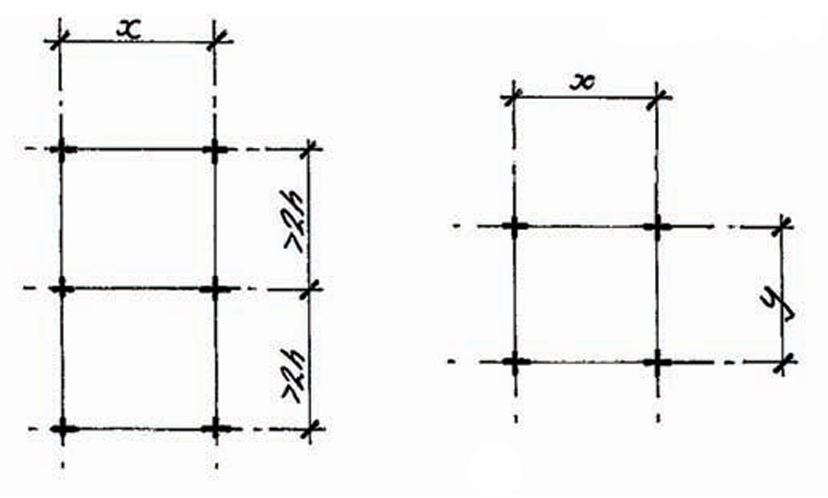
If point loads are spaced more than 2h apart (Figure 4a), the following expressions should be used to calculate the internal point load capacity on the floor slab:
If (a/l)= 0; then:
P_{u,0}=[2\pi\frac{1.8x}{l}](M_{+ve}+M_{-ve})If (a/l)>0.2; then:
P_{u,0.2}=[\frac{4\pi}{1-\frac{a}{3l}}+\frac{1.8x}{\frac{2l-a}{2}}](M_{+ve}+M_{-ve})Where: x represents the distance between the centerlines of the storage rack posts.
As the distance x increases, the floor slab’s capacity tends towards that for single point loads. When pairs of loads are positioned near edges, the internal load capacity can be multiplied by the ratio of the internal point load to the edge point load capacities.
In cases where four-point loads are placed x and y apart (Figure 4b), and both dimensions exceed 2h, the applied loading on the floor slab is typically less than for single point loads. For such groups, the following expressions should be used to determine the point load capacity of the slab:
If (a/l)= 0; then:
P_{u,0}=[2\pi\frac{1.8(x+y)}{l}](M_{+ve}+M_{-ve})If (a/l)>0.2
P_{u,0.2}=[\frac{4\pi}{1-\frac{a}{3l}}+\frac{1.8(x+y)}{\frac{2l-a}{2}}](M_{+ve}+M_{-ve})Where: y denotes the orthogonal distance between the centerline of the storage rack posts perpendicular to x.
If any distances between posts are greater than 3.5l, the previously described single point load capacity applies.
Line Load
When considering line loads, their location in the slab affects their capacity similarly to concentrated point loads. The key to deriving the slab’s capacity to resist a line load is what we describe as the characteristic of the floor slab system λ, defined as follows:
\lambda=(\frac{3k}{E_{cm}h^3})^{1/4}Once we calculate λ, we can determine the line load capacity (Pline) using the following expression:
P_{line}=4\lambda M_{un}When the line load is less than 3/λ to an edge of a floor slab, the expression changes to:
P_{line}=3\lambda M_{un}It’s important to note that the line load capacity should be compared to the unfactored line load, as relevant partial factors have already been applied to derive the slab’s line load capacity.
Imposed Area Loads
Area loads, like line loads, raise significant concerns, particularly when items are stacked using pallets. The characteristic system of the slab becomes crucial in this regard. The capacity of a slab to withstand an area load (q) is defined as follows:
q=5.95 \lambda^2 M_{un}The value of q is typically expressed in terms of kN/m2. The area over which these loads can be distributed is defined as π/l, and they must be spaced at least π/2 meters apart. This distance is commonly referred to as the ‘critical aisle width,’ determining where pallets can be stacked within a warehouse. Similar to line loads, the applied unfactored load should be compared against the capacity due to the inclusion of partial factors in its determination
Punching shear
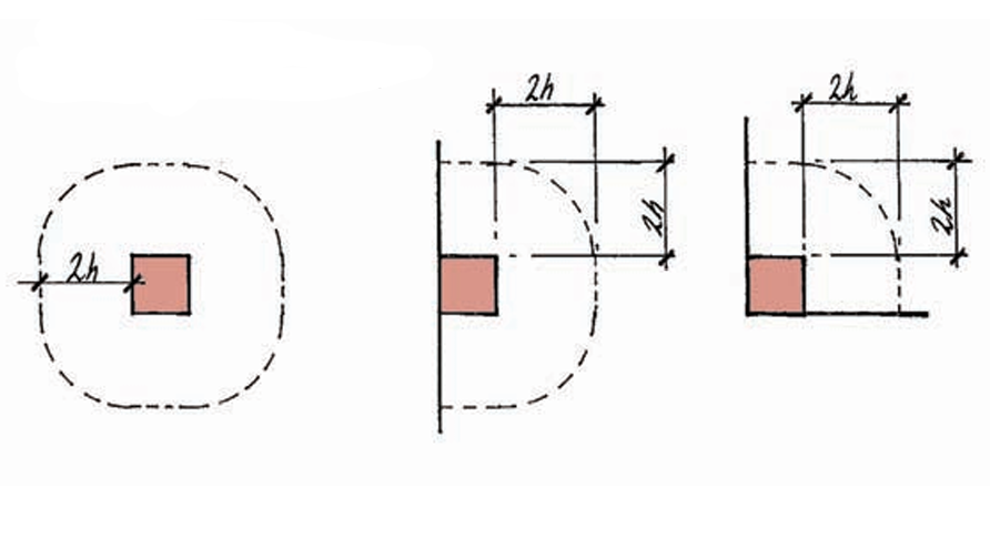
Punching shear failure poses a considerable risk in ground bearing slabs, especially when tall storage racks are placed on them. Therefore, it’s crucial to conduct punching shear checks on ground bearing slabs during their design phase. Fortunately, their direct support from a subgrade offers some protection against punching shear failure. The critical perimeter, along which the slab must undergo checks, extends 2h from the face of the baseplate to the storage rack posts. Additionally, the corners of this critical shear perimeter should be rounded (see Figure 5).
Given that the ratio a/l is less than 0.2, a ground bearing slab exhibits improved resistance against punching shear resulting from applied design point loads P. To address this, reactions Rp and Rcp (for mid-span and edge locations, respectively) can be calculated, which are subtracted from the applied design point load. This reduced force is then utilized to calculate the applied punching shear to the slab. The following formulas can be employed to determine these reactions:
For Internal point load reduction:
R_p=1.4(\frac{h}{l})^2P+0.47(b+d)\frac{dP}{l^2}For Edge and corner point load reduction:
R_p=2.4(\frac{h}{l})^2P+0.8(2b+d)\frac{dP}{l^2}Where: P represents the unfactored point load; b denotes the width of the baseplate to the storage rack post; d signifies the length of the baseplate to the storage rack post.
Worked Example
Determine the load carrying capacities of a ground bearing floor slab, 150mm thick, reinforced with steel fibres, for a storage warehouse, based on the following material properties: Concrete strength class C32/40 EN 14651 Notched beam test results:
fR,1 = 2.2 N/mm2 fR,2 = 2.0 N/mm2 fR,3 = 1.8 N/mm2 fR,4 = 1.5 N/mm2
The soil has a k value of 0.05N/mm2/mm. The presence of stud partitions is assumed, and there is no available information on the chosen storage rack system. Calculate the single point, line load, and area load capacity of the slab at internal, edge, and corner locations.
Flexural Capacities
Reinforced section
M_u=\frac{h^2}{\gamma_m}(0.29\sigma_{r4}+0.16\sigma_{r1}) =\frac{150^2}{1.5}((0.29\times0.45\times1.5)+(0.16\times0.37\times2.2))4.9kN.m/m
Unreinforced section
M_{un}=f_{ctd,fl}(\frac{h^2}{6})f_{ctd,fl}=f_{ctm}\times(1.6-\frac{h}{1000})/\gamma_m \ge \frac{f_{ctm}}{\gamma_m}f_{ctd,fl}=2.9N/mm^2M_{un}=\frac{150^2}{6}\times2.9=10.9kN.m/mRadius of Contact Area & Relative Stiffness
To determine the capacity of the ground bearing slab, we must determine the ratio of the radii, thus the radius of contact area and the relative stiffness is first determined.
Radius of Contact Area:
a=\sqrt \frac{100\times100}{\pi} =56.4mmRelative Stiffness:
l=(\frac{E_{cm}h^3\times10^{6}}{12(1-\nu^2)k})^{1/4}\frac{3300\times150\times10^6}{12(1-0.2^2)0.05}=20970mmRatio of Radii:
\frac{a}{l}= \frac{56.4}{20970} =0.003 =0Having determined the ratio of the radii, we can now determine the load capacitites of the ground bearing slab.
Point Load Capacities
Internal:
P_{u,0}=2\pi(M_{+ve}+M_{-ve}) =99.5kNEdge:
P_{u,0}=\pi\frac{(M_{+ve} +M_{-ve}}{2}+2M_{-ve}
=46.5kN
Corner:
P_{u,0}=2M_{-ve}= 21.75kNLine Load Capacities
\lambda=(\frac{3k}{E_{cm}h^3})^{1/4}=0.00108Internal:
P_{line}=4\lambda M_{un} =47.0kN/mCorner:
P_{line}=3\lambda M_{un} =35.2kN/mArea Load Capacity
q=5.95 \lambda^2 M_{un} =75kN/m^2Finally punching shear check should be checked at the internal, edge and corner of the ground bearing slab to ensure that it doesn’t govern the design. This is done using the equations presented in article.
Also see: Structural Analysis of Beams on Elastic Foundations
Sources & Citations
- The Concrete Society (2003) TR34 Concrete industrial ground floors (3rd ed.) Camberley, Surrey: The Concrete Society
- The Institution of Structural Engineers (2013) Steel fibre reinforced concrete ground bearing slabs, (Technical Guidance Note 11 (Level 2). London, UK: The Institution of Structural Engineers
- The Concrete Society (2007) TR63 Guidance for the design of steel-fibre reinforced concrete Camberley, Surrey: The Concrete Society
- The Institution of Structural Engineers (2013) Ground bearing slabs, (Technical Guidance Note 30 (Level 1). London, UK: The Institution of Structural Engineers.