This article provides an introduction to ground bearing floor slabs, touching on the slabs’ reinforcement by considering both historical use of mesh as well as current plastic and steel fiber reinforcement methods.

Ground bearing floor slabs, as the name implies are slabs that rest directly on the floor. They are commonly encountered in many industrial installations like warehouses or factories. They can also be utilized in various structures lacking a basement, contingent upon suitable ground conditions.
Designing and detailing these slabs involves a complex process due to the interaction between the natural and/or man-made ground and the rigid concrete floor slab, posing challenges related to cracking, movement, and flatness. Achieving utmost flatness is very crucial for factory floors and warehouses where operational efficiency relies on a precisely levelled floor.
This article introduces ground bearing slabs, discussing their reinforcement through historical mesh usage and modern methods involving plastic and steel fibers.
Ground Bearing Slabs
When casting concrete floor slabs directly onto the ground, their performance relies on both their rigidity and the interaction with the underlying soil. Larger floors require internal joints to prevent cracks from developing within the slab, a topic previously addressed in an article titled “Cracks in Concrete.”
Another crucial aspect influencing the design and specification of ground bearing concrete floors is the nature of the loads they must support. While non-specific human occupancy assumes a nominal load and the primary requirement is a relatively flat surface resting on the ground, industrial floors face different requirement. These floors typically support heavy machinery, racking, and transportation equipment such as forklifts, necessitating careful consideration to accommodate high point loads and achieve a very flat and level finish. Furthermore, the positioning of joints within the slab affects the placement of supports for machinery and storage racks. All of these issues will be addressed subsequently under separate sections in this article.
Components of a Ground Bearing Slab
Assuming it is constructed as a single layer, a typical ground bearing floor slab comprises five components, as illustrated in Figure 1 and summarized as follows (from bottom to top):

- Subgrade: The soil against which the ground bearing slab construction is positioned, but not poured.
- Subbase: A graded material, typically composed of broken masonry and/or rocks.
- Slip membrane: Provides a surface against which the concrete slab can flex independently of the subbase. It also acts as a barrier against ground-borne gases such as methane, radon, or carbon dioxide, as well as moisture.
- Reinforced concrete slab: The floor slab containing either a square fabric mesh or fibers, sometimes laid over a blinding layer of compacted sand.
- Wearing surface: The visible surface of the floor, usually treated with paint, sealant, or a screed.
In certain cases, an insulation layer is added, positioned similarly to the arrangement depicted in Figure 2. When exceptionally flat and level floors are needed, a two-layered ground bearing slab becomes necessary. These slabs incorporate a leveling screed to optimize surface flatness (as shown in Fig. 2). The components of this slab (listed from bottom to top) include:
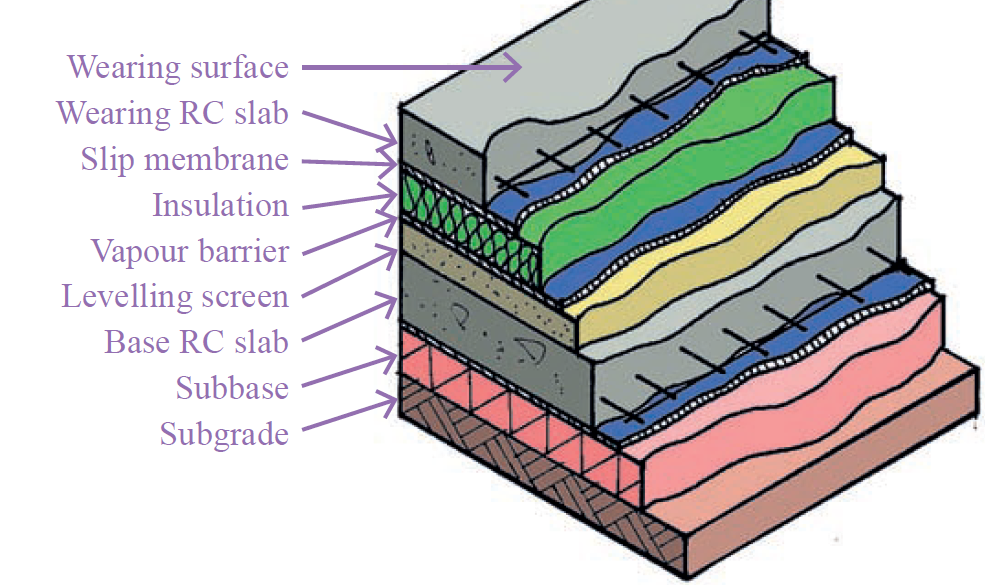
- Subgrade
- Subbase
- Slip membrane
- Base slab: A reinforced concrete slab upon which a leveling screed is placed.
- Vapour barrier: Installed to safeguard insulation material
- Insulation: Essential for thermally sensitive environments requiring ultra-flat and level surfaces
- Slip membrane
- Wearing concrete slab: The floor slab containing either a square fabric mesh or fibers
- Wearing surface
Both types of floor slabs adhere to the guidelines outlined in BS 8204: Part 2 – Screeds, bases and in situ floorings – Concrete wearing surfaces – Code of practice.
Joints in Ground Bearing Slabs
Let’s break down why ground bearing slabs have joints. First off, there are two main reasons: crack control and making sure the construction process goes smoothly.
When it comes to construction, you’ll often find joints in floor slabs. They’re there not just as a measure of crack control but because there’s a limit to how much concrete you can pour in a day. These joints, also called construction or ‘day’ joints, help manage the pouring process.
Then there’s crack control. When slabs are reinforced with mesh, they’re cast in strips. These strips have joints that actually encourage cracks to form in a controlled way. These joints, usually saw cuts spaced about every 6 meters, help deal with the shrinkage that happens as the concrete slab cures.
But even with all these precautions, it’s pretty much impossible to avoid cracks entirely. So, what’s the solution? Well, you guide those cracks to specific spots where they won’t cause too much trouble. Sometimes, you’ll see protection measures like folded metal channels or plastic caps put over these joints to keep things in check. We call these protected joints ‘armored joints’. Check out Figure 3 for an example.

Now, if you’re using steel or plastic fibers to reinforce the slab, you’re in luck. Those fibers add flexibility to the concrete, making it less likely to crack, so you might not need as many anti-crack joints.
Another strategy for crack control is by introducing movement joints within a slab. These joints allow the slab to shrink without getting all bent out of shape. They can handle sideways movement along their length and even resist vertical shifts, which helps prevent any uneven surfaces from forming (see Figure 4).

And here’s something to think about: in places where a ground bearing slab deals with big temperature swings, like in a cold-store or an outdoor slab, you’ll need expansion joints. These joints let the slab expand and contract as the temperature changes. Trust me, the movements caused by temperature changes can be pretty significant, sometimes even more than what the slab goes through while it’s setting.
Also, it’s crucial to shield joints from vehicle and pedestrian activity to prevent concrete damage. Once the slab has fully dried and surpassed the standard 28-day limit, apply sealant to the joint. It’s advised to delay joint treatment until later in the construction schedule, as concrete keeps setting and shrinking for months after casting.
Isolation of Vertical Elements
Vertical elements within the structure, such as columns and walls need to be isolated from the ground bearing slab in order to allow for the slab to expand against them without resulting in cracking. By removing these points of stiffness/restraint the floor slab is free to move around vertical elements. The form of isolation is a cast joint that is filled with a compressible material and is typically 10-20mm wide, depending on the predicted movement of the slab. Layouts of joints around columns are shown in Figure 5.

Uniformity of Surfaces
Achieving precise flatness and levelness during the installation of a floor slab is frequently crucial. In warehouses with high ceilings, where tall storage equipment is common, proper alignment of this equipment on the ground is paramount. Any unevenness or lack of consistent levelness in the floor slab could potentially pose dangers, making the operation of warehouse equipment hazardous.
To address this issue, the specifier for the ground bearing slab construction must establish reasonable tolerances based on its intended use. Typically, this involves setting standards for flatness over a 300mm length and levelness measured across 3m intervals. The Concrete Society’s Technical Report No. 34: Concrete Industrial Ground Floors identifies two key properties against which floor slabs can be assessed. These properties serve as benchmarks for determining compliance with specified requirements. Table 1, a condensed version of Table 4.2 in TR34, outlines the allowable limits for flatness and levelness of ground floor slabs.
| Floor use | Flatness (mm) | Level (mm) | ||
| 95% | 100% | 95% | 100% | |
| Other Installations requiring extremely flat surface | 2.5 | 4.0 | 4.5 | 7.0 |
| Warehouses > 8m span | 3.5 | 5.5 | 5.5 | 12.0 |
| Warehouses<8m span | 5.0 | 7.5 | 10.0 | 15.0 |
According to Table 1, 95% of on-site measurements must meet the stricter criteria, while all surveyed samples must adhere to the specified limits. Furthermore, the floor slab’s level should not deviate more than 15mm from the established datum.
Time vs. flatness
While considerable effort is invested in ensuring that the floor slab meets the standards outlined in Table 1, it’s essential to acknowledge the impact of time on its flatness. Three main factors contribute to this: deflection, unexpected settling of the underlying soil, and curling of the slab itself. Deflection can be mitigated by designing a sufficiently rigid slab to prevent significant issues. Addressing unexpected settlements requires thorough site investigations before construction begins. Curling, a well-known occurrence during slab curing, causes edges and corners to lift, sometimes even years later. Counteracting curling is challenging, primarily involving restraining concrete shrinkage by ensuring adequate thickness and correct membrane installation.
Impact on Subgrade Materials
There’s a variety of subbases out there, each with its own composition and ability to withstand pressure. The type of soil beneath the subbase also matters for determining the slab’s capacity. One crucial factor is the Californian Bearing Ratio (CBR), which you can learn more about in the article “Site Investigations in Foundation Design.”
When designing a ground-bearing slab, it’s vital to consider the impact on the subgrade material. This material will bend under pressure, affecting how well the ground-bearing slab performs. There are two ways to model soil interaction: one treats it like a dense liquid that deforms proportionally under load, while the other sees it as elastic, causing continuous deflection of the slab under load. The reality usually lies somewhere in between, making modeling quite challenging.
The prevailing view favors the first model, often called the ‘Winkler Model,’ for designing ground-bearing slabs. By assigning a resilience modulus (k) to the soil, you can figure out the necessary slab thickness. The value of k ranges from 0.015 to 0.3 N/mm3 and depends on the soil’s resistance to compression.
Steel and plastic reinforcement and fibres
In ground-bearing slabs, steel reinforcement typically involves a square mesh positioned at the slab’s bottom, with a 50mm cover. This setup boosts the slab’s flexibility and helps distribute loads among different sections by tying through crack-induced joints. However, it doesn’t do much to enhance resistance against shrinkage during curing. Alternatively, fiber reinforcement can be used to create ‘jointless’ slabs, provided specific conditions like slab size and special curing techniques are met to minimize cracking risks.
Instead of mesh reinforcement, steel or plastic fibers can be integrated into the slab mix to enhance load-bearing capacity and resist shrinkage effects. These fibers are designed with hooks to enhance bonding with the concrete. The concrete’s flexibility depends on the volume of fibers added during mixing.
Finishes
The types of finishes applied to floor slabs can vary widely, ranging from simple paint coatings to screeds or various types of tiling. Often, the finish is essentially a sealant directly applied to leveled concrete, typically done using a power-float method. Timing is critical during this process: if the float is applied too early, surface cracks may develop in the concrete. Conversely, applying the finish too late renders the float ineffective, leading to an uneven floor surface that may require grinding to achieve levelness.
Also See: Floor Slab Construction – Precast Concrete Planks
Sources & Citation
- The Concrete Society (2003) TR34 Concrete industrial ground floors (3rd ed.) Camberley, Surrey: The Concrete Society
- The Concrete Society (2007) TR63 Guidance for the design of steel-fibre reinforced concrete Camberley, Surrey: The Concrete Society
- The Institution of Structural Engineers (2013) Ground bearing slabs, (Technical Guidance Note 30 (Level 1). London, UK: The Institution of Structural Engineers