This article showcases reuse, and refurbishment as a powerful strategy in the climate emergency by taking the Triton Square building in London as a case study. A building that has won the IstructE 2022 award for exhibiting the power of circular economy across the entire spectrum of the project.
Introduction
It’s no longer news that a global warming of 1.5°C and 2.0°C will be exceeded by mid-21st century, unless a drastic reduction in the emission of greenhouse gases is made to occur in the upcoming decades. Amongst the biggest contributors to these emissions is the construction industry. The construction industry, the world over is responsible for 40% of global greenhouse gas emission annually2. While another half of these emissions are also due to the embodied carbon of buildings. The annual global demand for steel and cement – a direct contributor of greenhouse gases amount to 2.5gigatonnes, twice the value it was in the year 20001.
In a previous article, (See: The Role of Structural Engineers in the Climate Emergency) this writer outlined extensively the role of the structural engineers in the climate emergency and reached the sound conclusion that, reducing material quantities is the structural engineer’s best response to the climate emergency. Rightly so, we are unlikely to see a rapid decline in the use of the two conventional materials (Steel and Concrete) largely responsible for these emissions anytime soon. In the same article, four strategies which the structural engineer could implement towards bringing global greenhouse gas emissions to acceptable values was outlined. The end goal of each strategy being material minimization.
Amongst the strategies listed is “Reuse and Refurbish”. This strategy involves delaying the obsolescence of manufactured structural components by planning for the long-term usefulness of the structural system put in place or where the structural system is deemed obsolete, the component can be demounted, refurbished & reused in new layouts. In more precise terms, to reuse and refurbish is to ensure that the components of any structure can be kept in use for as long as possible, either in the initial context in which they were designed or in future unforeseen context. Reuse & refurbish in other words means nothing is lost, nothing is created but everything is used at minimal economic and environmental cost. This is known as the circular economy.
In this article we’ll discuss the reuse, and refurbishment strategies adopted for the Triton Square building in London to enable the addition of three extra floors. Increasing the total floor area by 70% while achieving a SCORS A rating for the overall carbon per unit area for the scheme.
Triton Square – Original Design
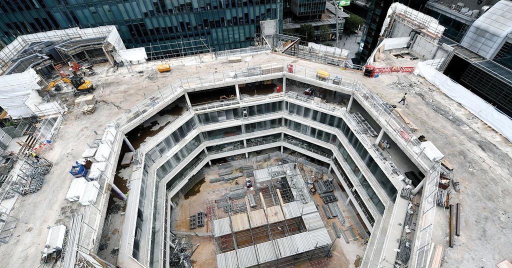
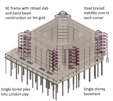
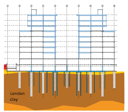
The Triton Square is a building located in the city centre of London. Originally designed by Arup in the 1990s, with anticipated future changes and likely modifications in mind. The original scheme involved a 72m x 72m scheme with six suspended floors and a single basement level. The structural form was very unusual with the structure lateral stability being ensured by concrete cores below ground and steel frames above ground level (Figure 1). The basement had retaining a wall only on the northside of the structure, due to the other sides being contiguous with the basement of neighbouring buildings. The piles used for the foundation were predominantly 1.2-1.8m in diameter.
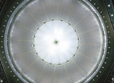
A very remarkable feature of the building is the central atrium. It was 36m x 36m and carved into the central portion of the building. It ran through the first floor of the building up till the 5th floor (Figure 2).
Prospects for Reuse & Refurbishment
The promise for reuse and refurbishment as hinted in the preceding section was being envisaged from the outset of the original design. Arup, had produced a resilient design, this ensured that the prospects for reuse was very high. However, the factors that made the dramatic difference were:
- New planning rules meant that the building height used in 1990s was no longer appropriate. This unlocked the possibility of considering the addition of extra floors3.
- The existing large central atrium lent itself to being filled in partially, creating extra floored area3.
- The building staircase design were very generous thus, allowing an increase in the building occupancy without any need for new escape routes3.
- The designed imposed loading considered were quite high, this meant that the resistance of the structural members could be enhanced by considering current code values3.
- The presence of ample data and information on the existing structure. Including the resident’s engineer records on the original piling works which mitigated the inherent risks of structural reuse and opened up the opportunity for additional resistance through strengthening procedures3.
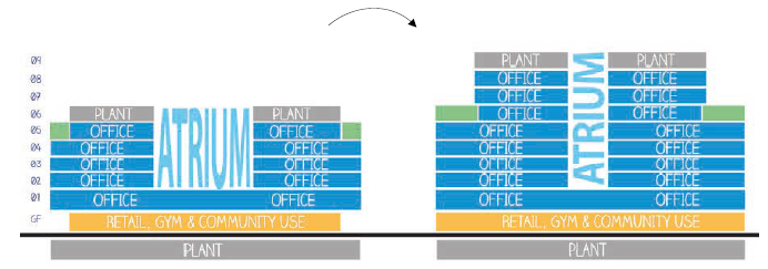
Having considered these opportunities, the risks and consequences of the procedures, the designers were able to increase the floored area of the original structure by 70% through the addition of three extra storey, partially infilling the large atrium and infilling most of the entrance atrium (Figure 3). The extra floors added were set back from the building perimeter. This was a very important decision of the structural reuse strategy as will be seen in the next section.
Triton Square – New Design
The strategy for reuse of the original design followed two basic principles: limit the loads, maximize structural resistance3. Structural elements that showed no increase or a decrease in loads in the new scheme were considered adequate without any further checks. While those witnessing an increase in loading was reassessed to current design codes.
Gravity Forces
As stated, one of the primary strategies was to limit the loads, hence the designers aimed to ensure that new floor areas were created with lightweight composite steel and concrete floor construction. The original design having considered a generous imposed loading of 5kN/m2 including permanent partitions was reduced to 4kN/m2. The imposed loading for roof plant was kept to the modest value of 4kN/m2 which was made possible by accommodating most of the heavy plants in the basement3.
However, despite these steps in reducing the gravity forces, many of the vertical loadbearing structural elements witnessed a surge in the loading due to the proposed changes. The most impacted columns and piles were of course those in the central atrium for which the increase was almost in threefold of the original as a result of the increased floor area and additional floors.
As a first step, the designers back-calculated the structural resistances of the existing columns and foundations based on the current codes of practice. In the case of the foundation, the information at the disposal of the resident engineer indicated the as built pile toe level and the levels at which the London clay was encountered during the original piling works. This ensured that the resistance of the pile can be estimated to current design standard, which in any case proved to be significantly higher than the specified loads.
Since the extra floors were set back from the building perimeter, this saw that the perimeter columns only noticed a slight or no increase in loading. Hence columns and foundations mostly located in the perimeter of the building did not require strengthening. This proved to be a valuable decision, because the strengthening of this columns would’ve been very challenging due to the immediate proximity of the building façade and basement perimeter to neighbouring buildings (Figure 4).
Where the structural resistance of columns and foundations were found to be less than the new loading values, these required strengthening and this was carried out.
Lateral Forces
One doesn’t need to guess. The addition of three floors would translate into a significant increase in the lateral loads on any low-medium rise building. In the original scheme, lateral stability was ensured through a combination of concrete cores and steel braced frames. By braced steel frames above ground level and with concrete shear walls at basement level.
As a sub-strategy to reduce the impact of the lateral forces particularly from wind, the directional assessment method of calculation was considered, accounting for parameters such as distance to sea and obstructions by neighboring buildings which would otherwise have being ignored. This did help to reduce the lateral forces; however, it was found that the resistance of the original braced steel frame was still exceeded.
To minimize the impact of this increased lateral loads on the braced frames, the contribution of the overall concrete frame to lateral stability had to be taken into consideration. This had been designed to resist only gravity forces only. Hence each column to beam connection had to be back-calculated. Where it was found that the steel frame and connection resistances were exceeded, they were considered for strengthening.
Strengthening Procedures
Strengthening was mainly required for the vertical load bearing elements, such as columns, walls and foundation elements. The strengthening of the affected elements was achieved through a variety of approaches.
Foundations
Pile strengthening involved installing additional piles from within the basement. A key consideration was the limited headroom which in turn limited the size of the piling rig that could be used3. Hence the diameter of the supplementary pile was limited to 450mm3.
It had been envisaged that connecting existing pile with supplementary piles would be possible by simply providing supplementary piles by forming individual pile caps at the location where they would be required. This solution evolved into a piled raft in the mid-section of the basement due to the large number of supplementary piles required. However, it led to a saving of about 30% in the length of piles required.
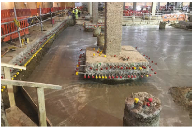
Individual pile caps were still used in core areas and adjacent to the retaining wall to the north of the basement. This made it possible to maintain a continuous horizontal ‘picture frame’ of concrete connecting all four stability cores and propping the base of the retaining wall throughout all stages of the strengthening works. Supplementary piles were also installed through local openings in the existing ground-bearing basement slab prior to more extensive demolition works taking place.
The breaking out of the existing slab, and subsequent construction of pile caps and raft, took place in a sequential manner so as not to undermine the concrete. Once existing piles were exposed, their original steel casing was cut open, leaving their rough concrete surface exposed. Existing reinforcement in the slab above the piles was left projecting, and new pile caps or raft reinforcement were connected to existing by means of couplers, with new dowel bars installed below. Load transfer between the existing piles and the new pile caps or raft happened through a combination of Coulomb friction, dowel action and interlocking (Figures 5).
The settlement of the resulting foundation was monitored at all stages using a 3D finite element software package of the structure interacting with the ground. Throughout the remedial works, the values were monitored and all measured values were found to be within the limit of predictions.
Concrete Columns
The default strengthening procedure for concrete columns was ‘encasement’. The surface of the columns to be strengthened were first scrapped in order to promote bond between the existing concrete and fresh concrete to be poured. Reinforcement was then fixed around the scrapped concrete and a 125 -150mm thick high strength concrete was cast.3 This was pumped at high pressure from bottom -top to ensure adequate compaction and bearing at the underside of the floors above (Figure 6).

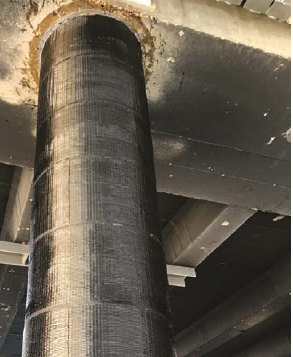
For columns that’s experienced only a modest loading increase in the new scheme, these were strengthened using fiber reinforced plastics (FRP) rapping. This was beneficial in terms of cost and program, and offered no reduction in floor area (Figure 7)
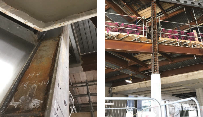
Steel Columns
For steel columns, the strengthening procedure involved concrete encasement or addition of steel plates (Figure 8). The choice of the strengthening procedure to adopt depended on accessibility and the failure mode of the original steel column under the new design forces. For instance, C columns only failing in buckling but not in local section capacity need not the strengthening to be continuous through the floors making the use of discrete strengthening plates suitable. Whereas columns failing in local capacity required the strengthening to be continuous through floors hence their strengthening was achieved through concrete encasements.
Structural Embodied Carbon
The finished project added 13100m2 net and 16400m2 gross area of floor space for an additional embodied carbon of 6400tC02e a number achieved through active use of cement replacement3. 70% GGBS for most elements). This gives a carbon footprint per unit of additional area of 360kgC02e/m2.
This isn’t a dramatically low figure but it is sparingly low considering the significance of the amount of strengthening work carried out. The figure highlights the significant benefits of reuse. By retaining and extending the existing structure of the Triton Square, 35,000t of concrete and 1900t of reinforcing steel were saved from demolition. The extension brought the total floor area to (32100m2 net and 47200m2 gross). The carbon footprint is then 136kgC02e/m2 achieving a SCOOR A rating. This compares very favorably with the ‘current practice’ benchmark value of 350kgCO2e/m2, as well as meeting the International Panel on Climate Change’s 2030 carbon budget target, set out in the article introducing the SCORS scheme2.
In summary and to conclude, the Triton Square is a building with sustainability at its core, the reuse of the existing building showcases the potential value that can be realized from reusing and refurbishing an existing building rather than demolish it. Not only are we able to produce environmentally efficient buildings, minimize embodied carbon, thereby reducing the effects of climate change but we’re also able to produce cost efficient structural solutions
See: Engineering Ethics: Reviewing an Engineer’s Work
Sources & Citations
- Tayler H. (2020) Institution of Structural Engineers ‘A short guide to reusing foundations’, The Structural Engineer, 98 (11), pp. 20–23.
- Arnold W., Cook M., Cox D., Gibbons O. and Orr J. (2020) Institution of Structural Engineers ‘Setting carbon targets: an introduction to the proposed SCORS rating scheme’, The Structural Engineer, 98 (10), pp. 8–12
- Robertson A., Strule E. (2020) Institution of Structural Engineers ‘Triton Square, London–low-carbon development through reuse of an existing building’, The Structural Engineer, 99 (3), pp. 30–35
Thank You!!!