The Eurocode defines a wall as a vertical or near-vertical structural element with a breadth and length that is greater than 4 times its thickness. Although a minimum thickness of 150 mm is possible for a wall, it is recommended that 180-250 mm aid detailing and construction. A wall’s thickness is determined based on the forces it is being subjected to, required fire resistance, durability and buildability.
In the last post, we derived the actions on the shear wall of a building. It was shown that there are three types of actions a shear wall is required to withstand: axial forces, in-plane bending and transverse bending out of the plane of the wall. In this post, we are going to consider how to design concrete shear walls according to Eurocode 2.
The procedure for designing a concrete wall is very similar to the design of concrete columns. Slenderness must be checked about the minor axes of the wall, the design moment determined by considering the effect of imperfections and second-order effect if critical. Finally, reinforcement is provided using column interaction charts.
Slenderness
Walls just like columns are required to resist compression forces, hence slenderness could be critical in the minor axis (perpendicular to the plane of the wall). The slenderness of a wall is defined by the ratio of the effective height to the thickness of the wall. Similar to columns, when a wall is slender its resistance to bending moments and axial forces are reduced and thus second-order effect
Section 5.6.2 in the Manual for the design of concrete buildings to Eurocode 2 explains that it is possible to simplify the process of determining the slenderness of concrete walls by using the following expressions
\frac { { l }_{ oz } }{ h } \le 4.38\left( 1.7-\frac { { M }_{ 1,z } }{ { M }_{ 2,z } } \right) \xi \quad not\quad slender\quad\frac { { l }_{ oz } }{ h } >4.38\left( 1.7-\frac { { M }_{ 1,z } }{ { M }_{ 2,z } } \right) \xi \quad slender\quad Where:
M1Z and M2z are the smaller and larger minor axis bending moments on the considered span respectively.
ξ is a function of the applied design axial load (NEd) per metre length of the wall and is defined as:
\xi =0.69\sqrt { \frac { \left( 1+2\omega \right) \left( 1000h{ f }_{ ck } \right) }{ { N }_{ Ed } } } \ge 1.0 where\quad \omega =1.53\frac { { A }_{ s } }{ 1000h{ f }_{ ck } }\quad or\quad 0.003\frac { { f }_{ yk } }{ { f }_{ ck } } \quad if\quad { A }_{ s }\quad is\quad unknown- fyk is the tensile or characteristic yield strength of reinforcement,
- fck is the characteristic cylinder compressive strength of the concrete
- h is the thickness of the wall
- loz is the effective height of the wall along its minor axis As is the area of vertical reinforcement in the wall
The effective length of the wall along it minor axis can be determined by applying coefficients in Table 1 or using the detailed procedure in BS EN 1992-1-1.

Determination of Design Forces
Minor Axis Bending
The minor axis moment is treated the same way as a concrete column. If the wall is slender second-order effects must be considered and the wall must be designed for additional bending moments. Generally, the design moment about the minor axis of a concrete wall is given as:
{ M }_{ Ed }=max\left\{ { M }_{ 2 }\quad ;{ \quad M }_{ zi }+{ N }_{ Ed }\left( { e }_{ 2z }+{ e }_{ a } \right) \right\} Where:
M1=is the smaller end moment in the minor axis of the wall derived from analysis
M2=is the larger end moment in the minor axis of the wall derived from analysis
Mzi=is the applied minor axis bending moment that is derived from analysis
{ M }_{ zi }=0.6{ M }_{ 2 }+0.4{ M }_{ 1 }\ge { 0.4M }_{ 2 }e2z =is the deflection of the wall in its minor axis due to axial factored design actions and needs to be considered only if the wall is slender.
{ e }_{ 2z }={ f }_{ yk }\left( \frac { { l }_{ 0z }^{ 2 } }{ d } \right) \cdot { 10 }^{ -6 }\quad in\quad mmea is the eccentricity of the applied design axial force due to ‘out of plumb’ state of the wall during construction. This is defined as:
\frac { { \theta }_{ i }{ l }_{ 0z } }{ 2 } where θi is a notional drift of the wall as stipulated (in mm) in Table 2.

f yk is the characteristic strength of reinforcement in N/mm2- d is the effective depth of reinforcement (mm) within the wall in its minor axis.
Major Axis Bending
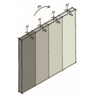
In the plane of the wall, the magnitude of the applied actions is determined by splitting the wall into some series of 1m strips. These can each be considered subject to axial compression and minor axis bending only, with the design of reinforcement based on the extreme fibre stresses in the wall (ft). Thus, in any 1 m section of the wall idealized. All applicable axial forces and bending moments are applied to each segment being considered, and each unit length is treated as a structural column see (Figure 2).
The extreme stresses of the fibers can be determined with the following formula.
{ f }_{ t }=\frac { N }{ Lh } \pm \frac { 6M }{ { hL }^{ 2 } } Where
- N= is the design axial force in the 1m strip of wall
- L= is the overall length of the wall
- h= is the overall thickness of the wall
- M= is the applied design major axis bending moment in the segment of the wall.
The resulting stress is then multiplied by the wall thickness (h) to create a stress per metre. The reinforcement can then be determined using a column design methodology where the bending of the minor axis as well as the axial stresses due to both the major axis bending and the axial forces are applied.
There’s a simplified approach that can be applied in instances where there is no significant minor axis bending moments being applied to a wall e.g. when supporting slabs of the same span and depth are either side of the wall. See section 5.6.4.1. of the Institution of Structural Engineer’s Manual for the design of concrete building structures to Eurocode 2.
Detailing Requirement
The detailing rules for reinforced concrete walls are defined in Clauses 9.6.2(1) and 9.6.3(1) of BS EN 1992-1-1 and can be summarised as follows
Area of Steel
- The minimum of 0.002 Ac split between both layers for vertical reinforcement, near and far face.
- The maximum area of vertical reinforcement is set at 0.04 Ac
- For horizontal reinforcement, the minimum is either 25% of the provided vertical reinforcement or 0.001 Ac, whichever is greater
- The minimum size of the bar for horizontal reinforcement is 0.25 times the diameter of the vertical reinforcement.
where: Ac is the overall cross section area of the wall
Spacing
The vertical bar spacing must not exceed 300 mm or 3 times the thickness of the wall, whichever is lower.
Where vertical reinforcement exceeds 2 percent of the cross-sectional area within any wall segment of 1 m wide, containment links shall be provided in similar fashion to concrete columns.
Worked Example
A 24m tall, 5.0m long and 200mm thick reinforced concrete shear wall is required to support a 200mm thick flat slab and in addition, provide lateral support to the 8 storey building in its plane. There are 8 columns between the shear wall and the next wall. Design the reinforcement in the wall at its base and mid-height. Assuming the wall is to be constructed from C30/37 concrete with a yield strength of 500Mpa. The critical design actions on this wall are presented in table 1. Take storey heights =3m
| Position | Axial Load (kN) | In-plane Moment (kN.m) | Transverse Moment (kN.m) |
| Mid-height | 1430.1 | 3240 | 72.7 |
| Base | 2862 | 12960 | 72.7 |
The data for this example is taken from the previous post. See Analysis of Shear Walls
Determination of Axial Forces in Wall
At Mid height
{ f }_{ t }=\frac { N }{ Lh } \pm \frac { 6M }{ h{ L }^{ 2 } }=\frac { 1430.1\times { 10 }^{ 3 } }{ 5000\times 200 } \pm \frac { 6\times 3240\times { 10 }^{ 6 } }{ 200\times { 500 }^{ 2 } } \\=1.43\pm 3.89{ f }_{ t }=5.32{ N/mm }^{ 2 }\quad or\quad { 2.46N/mm }^{ 2 }force\quad in\quad wall\quad { N }_{ max,1 }=5.32\times 200\\=1064kN/mAt the Base
{ f }_{ t }=\frac { N }{ Lh } \pm \frac { 6M }{ h{ L }^{ 2 } } =\frac { 2862\times { 10 }^{ 3 } }{ 5000\times 200 } \pm \frac { 6\times 12960\times { 10 }^{ 6 } }{ 200\times { 500 }^{ 2 } } \\=2.86\pm 15.55{ f }_{ t }=18.41{ N/mm }^{ 2 }\quad or\quad { 12.69N/mm }^{ 2 }force\quad in\quad wall\quad { N }_{ max,2 }=18.41\times 200\\=3682kN/mSlenderness Verification
Slenderness verification is more critical for the stack at the base than that at mid-height, therefore the check will be carried out for the base stack only.
\omega =0.003\frac { { f }_{ yk } }{ { f }_{ ck } } =0.003\times \frac { 500 }{ 30 } =0.05 \xi =0,69\sqrt { \frac { \left( 1+2\omega \right) \left( 1000h{ f }_{ ck } \right) }{ { N }_{ max } } } \ge 1.0=0.69\sqrt { \frac { \left( 1+2\cdot 0.05 \right) \left( 1000\times 200\times 30 \right) }{ 3682\times { 10 }^{ 3 } } } =0.92\ge 1
{ M }_{ 1z }=-72.7kN.m\quad { M }_{ 2z }=72.7kN.mThe wall
{ l }_{ oz }=0.75\times 3000=2250mm\frac { { l }_{ oz } }{ h } \le 4.38\left( 1.7-\frac { { M }_{ 1,z } }{ { M }_{ 2,z } } \right) \xi \frac { 2250 }{ 225 } \le 4.38\left( 1.7-\frac { -72.7 }{ 72.7 } \right) \cdot 111.25<<11.83
\therefore \quad Wall\quad is\quad not\quad slender
Minor Axis Bending Moment
{ M }_{ Ed,z }=max\left( { M }_{ 2 }\quad ;\quad { M }_{ zi }+{ N }_{ Ed }\left( { e }_{ 2z}+{ e }_{ a } \right) \right){ M }_{ 2z }=0.6{ M }_{ 2z }+{ 0.2M }_{ 1z }\ge { 0.4M }_{ 2z }=0.6\left( 72.7 \right) +0.4\left( -72.7 \right) \ge 0.4\left( 72.7 \right)\\=29.08kN.m
{ e }_{ 2z }=\quad 0\quad (wall\quad is\quad not\quad slender) { e }_{ a }=\frac { { \theta }_{ i }{ l }_{ 0z }^{ 2 } }{ 2 } \quad ;\quad { \theta }_{ i }=\frac { 1 }{ 400 } \quad (interpolating)=\frac { 1/400\times 2250 }{ 2 } =2.81mmAt Mid-height
{ M }_{ Ed,z }=max\left\{ 72.7;\quad 29.08+1604\left( 0+2.81 \right) \right\}=72.7kN.m
At Base
{ M }_{ Ed,z }=max\left\{ 72.7;\quad 29.08+3682\left( 0+2.81 \right) \right\}=72.7kN.m
Reinforcement Design
Column interaction charts will be used in providing reinforcement in the wall. Assuming concrete cover =30mm, 16mm vertical bars and 10mm horizontal bars, effective depth is:
d=200-\left( 30+10+16/2+10 \right) =142mm
\frac { d }{ h } =\frac { 142 }{ 200 } =0.71\quad use\quad chart\quad of\quad \frac { d }{ h } =0.8Mid-height
\frac { M }{ { bh }^{ 2 }{ f }_{ ck } } =\frac { 72.7\times { 10 }^{ 6 } }{ 1000\times { 200 }^{ 2 }\times 30 } =0.06 \frac { N }{ bh{ f }_{ ck } } =\frac { 1064\times { 10 }^{ 6 } }{ 1000\times 200\times 30 } =0.18from\quad chart\quad \frac { { A }_{ s }{ f }_{ yk } }{ bh{ f }_{ ck } } =0.1 { A }_{ s,req }=\frac { 0.1\times \left( 1000\times 200\times 30 \right) }{ 500 } =1200{ mm }^{ 2 }This is the area of steel required in both faces of the wall. The area of steel required per face is half this value.
\frac { { A }_{ s,req } }{ 2 } =\frac { 1200 }{ 2 } =600{ mm }^{ 2 }/m/faceUse\quad H16-250mm\quad centres\quad \\({ A }_{ s,prov }=804{ mm }^{ 2 }/m)Base
\frac { M }{ { bh }^{ 2 }{ f }_{ ck } } =\frac { 72.7\times { 10 }^{ 6 } }{ 1000\times { 200 }^{ 2 }\times 30 } =0.06\frac { N }{ bh{ f }_{ ck } } =\frac { 3682\times { 10 }^{ 6 } }{ 1000\times 200\times 30 } =0.61from\quad chart\quad \frac { { A }_{ s }{ f }_{ yk } }{ bh{ f }_{ ck } } =0.25 { A }_{ s,req }=\frac { 0.25\times \left( 1000\times 200\times 30 \right) }{ 500 } =3000{ mm }^{ 2 }/mThis is the area of steel required in both faces of the wall. The area of steel required per face is half this value.
\frac { { A }_{ s,req } }{ 2 } =\frac { 3000}{ 2 } =1500{ mm }^{ 2 }/m/faceUse\quad H16-125mm\quad centres\quad ({ A }_{ s,prov }\\=1608{ mm }^{ 2 }/m)Detailing Checks
Minimum Area of Steel
{ A }_{ s,min }=0.002{ A }_{ c }=0.002\times 1000\times 200\\=400{ mm }^{ 2 }/mReinforcement\quad per\quad face\quad =\frac { 400 }{ 2 } \\=200{ mm }^{ 2 }/m{ A }_{ s,prov }=\left( 804,1608 \right) { mm }^{ 2 }>200{ mm }^{ 2 }\quad o.kHorizontal Reinforcement
{ A }_{ s }=max\left\{ 0.25{ A }_{ spro }\quad ;\quad 0.001{ A }_{ c } \right\} max\quad (0.25\times 1608\quad or\quad 0.001\times 200\times { 10 }^{ 3 })=402{ mm }^{ 2 }/mUse\quad H12-250mm\quad centres\quad \\ \left( { A }_{ s,prov }=452{ mm }^{ 2 }/m \right)This design assumes that the base is sufficient to withstand the overturning moment. For practical purposes, the tension at the base of the wall must be resisted by the weight of the foundation. If piles are used, the piles must be designed to resist tension.
Further Reading & References
The Institution of Structural Engineers (2006) Manual for the design of concrete building structures to Eurocode 2, London: The Institution of Structural Engineers.
The Institution of Structural Engineers (2012/2013) Technical Guidance Notes 1-5 and 17 (Level 1) and 3 (Level 2), The Structural Engineer, 90 (1-3, 10) and 91 (3).
The Concrete Centre (2009) Worked Examples to Eurocode 2: Volume 1 [Online] http://www.concretecentre.com/pdf/ Worked_Example_Extract_Slabs.pdf (Accessed: March 2014).
Thank you for reading, kindly share this post.
canadian world pharmacy – how to buy cialis cialis 10mg coupon
where can i buy sildenafil over the counter – female viagra pill buy sildenafil tablets india
generic cialis online uk – 5mg dose of cialis prescription tadalafil preion cost
ivermectin online – stromectol online pharmacy ivermectin where to buy
casino moons online casino – site casino world
online ed pills – buy ed pills erectile dysfunction drugs
can you buy prednisone in canada – buy predisone steriods prednisone 5mg
india cialis online – Cialis without prescription where can i buy cialis online usa
purchase oral ivermectin – ivermectin generic name ivermectin lotion 0.5
hims ed pills review – strongedpl natural pills for erectile dysfunction
buy ventolin inhaler – ventolin generic brand buy ventolin
how to get cytotec without prescription – cytotec usa cytotec for endometrial biopsy
doxycycline 50 mg india – doxycycline 25mg tablets cost of doxycycline canada
drug neurontin – neurontin discount levothyroxine 150 mcg
120mg viagra – order viagra india
best tadalafil brand in india – cost of cialis
vardenafil com – vardenafil best price buy vardenafil online usa
ivermectin cost australia – ivermectin 1 cream generic buy ivermectin cream for humans
20mg prednisone – prednisone 5 mg cheapest prednisone 7.5 mg daily
buy accutane cheap online – accutane discount accutane pill
antibiotics without a doctor’s prescription – buy amoxicilin 500 mg canada buy amoxicillin online
methylprednisolone costs – methylprednisolone 16mg tab lyrica
viagra 25 mg coupon – Buy viagra with discount canadian pharmacy viagra 200 mg
buy cialis over the counter in canada – Cialis prescription tadalafil tablets for female hindi
stromectol 3 mg tablets price – site ivermectin over the counter canada
prednisone nz – prednisone 10mg pack prednisone 10 mg purchase
furosemide 20 mg tab – clomid 100 mg tablet buy cheap lasix