This article highlights the advantages of composite columns over normal concrete or steel columns and offers guidance for designing composite columns to Eurocode 4.

Steel columns in multi-storey buildings will often require some form of fire protection. This is often achieved by encasing them in concrete. Prior to the 1950s, it was standard to use a low-strength wet mix to encase the steel-section. Because the concrete was low strength, the concrete’s contribution to the column’s strength and stability was disregarded. However, tests by researchers at the time soon demonstrated that using higher quality concrete and designing the column as a composite member could significantly increase in the load carrying capacity of the steel column ultimately resulting in cost savings.
This discovery of ‘composite columns,’ led to the development of the ‘cased strut’ design method. Initially outlined in BS 449, this method used permissible-stress calculations for steel members, specifically H or I-sections. Later, it evolved into a limit-state design approach. In this method, the concrete is considered in two ways: it is assumed to bear a small axial load and to decrease the steel member’s effective slenderness, thereby enhancing its axial load resistance. However, bending moment resistance is attributed solely to the steel, and the longitudinal reinforcement in the concrete is not factored into the resistance calculations.
This article explores the design of composite-steel column using the limit state design approach in the Eurocodes. In designing composite steel columns to the Eurocodes, both EN 1994-1-1 and EN 1994-1-2 provide extensive guidelines, including simplified methods. These simplified approach offers engineers a practical framework for analysis and design.
Simplified Method of Designing Composite Steel Columns
Designing composite columns involves considering material properties, cross-sectional geometry, loadings, and stability. The simplified method, outlined in EN 199-1-1, streamlines this process by assuming certain conditions and providing straightforward equations. These equations account for axial load, bending moment, and shear force distributions along the column’s length, resulting in a more efficient and practical design approach.
This simplified method relies on several assumptions to ensure a conservative design, which involves adhering to constraints detailed in EN 1994-1-1, particularly in articles 6.7.1, 6.7.3.1, and 6.7.3.3. Alternatively, the general design method in EN 199-1-1, article 6.7.3.2, has fewer constraints, accommodates any cross-section, and allows for higher concrete grades than C50/60. However, this article focuses on the simplified design method, which is used in 95% of practical cases.
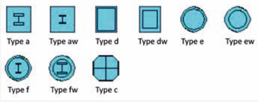
Supported cross-sections for the simplified method are described in EN 199-1-1, figure 6.13, and illustrated in Figure 1. These cross-sections are categorized into the following groups as mentioned in EN 199-1-1, article 6.7.3.1:
- Concrete-encased cross-sections (type a)
- Partially encased cross-sections (type ac)
- Concrete-filled rectangular and circular tubes (types b and c)
The general design method in EN 1994-1-1, article 6.7.3.2, can be applied to other cross-sections not covered by the simplified design method.
Member Verification
The member verification that controls the design of a composite column depends largely on derived actions on the columns. These checks are performed when internal forces are present for the specific combination being analysed. The designer has to decide whether the composite column is in pure compression only or whether a bending moment acts in one or both axes. The subsequent paragraphs will outline the different checks based on the aforementioned.
Column Under Pure Compression
If a composite column experiences only compression forces, possibly accompanied by shear forces and without bending moments, it is considered a pure compression case. In such instances, pure compression can be verified using either the simplified method or the European buckling curves as outlined in EN 199-1-1, article 6.7.3.3.2.
The simplified method verifies the compression check by reducing the compression resistance Npl,Rd using the minimum reduction factor from χy or χz. Mathematically the check for pure compression can be written as:
\frac{|N_{Ed}|}{min(\chi_y, \chi_z)N_{pl,Rd}}\le1Where: NEd is the applied compression force; NPl,Rd is the compression resistance of the steel section and χy or χz are reduction factors obtained from the buckling curves in Clause 5.5.1 of Eurocode 3-1. The European buckling curves presented as Figure 2 may be used for composite column design. They are selected on the basis of the type of steel section and the axis of bending.
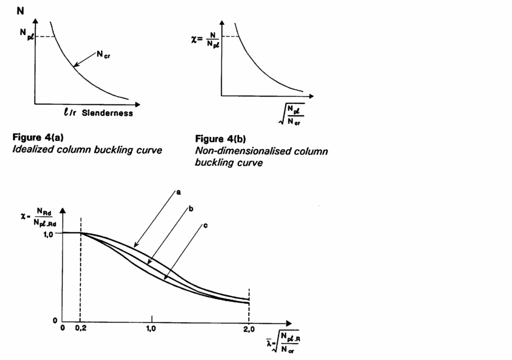
- Curve a – for concrete filled hollow sections
- Curve b – for fully or partially concrete encased I – sections buckling about the strong axis of the steel section
- Curve c – for fully or partially concrete encased I – sections buckling about the weak axis of the steel section
Compression Resistance
Depending on the chosen composite column cross-section (Figure), EN 1994-1-1, article 6.7.3.3.1, provides formulas for calculating the compression resistance Npl,Rd
For Concrete-encased type and partially concrete-encased type b, c d, compression resistance is given as:
N_{pl,Rd}=A_af_{yd}+0.85A_cf_{cd}+A_sf_{sd}For Concrete-filled tube (type e and f):
N_{pl,Rd}=A_af_{yd}+1.0A_cf_{cd}+A_sf_{sd}
Concrete-filled tubes can gain additional strength through confinement if both conditions of EN 1994-1-1, article 6.7.3.2, are met. When these conditions are satisfied, the compression resistance is determined by the following equation of EN 1994-1-1, rather than by the previously mentioned equation.
N_{pl,Rd}= \eta_aA_af_{yd}+1.0A_cf_{cc}+A_sf_{cd}Where: Aa; Ac & As are the areas of the structural steel section, areas of the concrete section and areas of the reinforcing steel respectively. fyd; fcd and fsd are the design yield strength of the structural steel section; design compressive strength of the concrete and the design yield strength of the reinforcing steel respectively.
Combined Compression and Uni-axial Bending
For a composite steel column with axial compression and bending moment in one axis, BS EN 1994, requires that the following expression is satisfied:
\frac{M_{Sd}}{\mu_d M_{pl,Rd}} \le 0.9Where: MSd is the design bending moment which may be factored to allow for second order effects; μd is the moment resistance ratio obtained from the interaction curve (Figure 3); Mpl,Rd is the plastic moment resistance of the composite section.
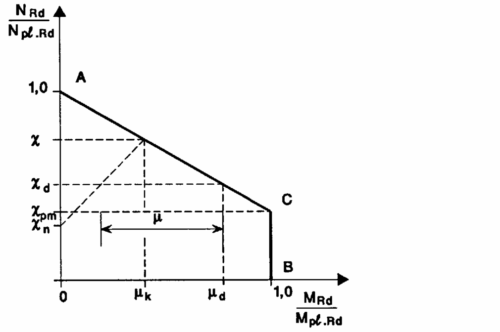
In order to comply with the UK National Annex, the moment resistance ratio for a composite steel column under the combined compression and uni-axial bending should be evaluated as follows:
\mu_d=\frac{\chi-\chi_d}{x(1-\chi_{pm})} \quad \chi_d \ge \chi_{pm}\mu_d=1-\frac{1-\chi)\chi_d}{\chi(1-\chi_{pm})\chi} \quad \chi_d < \chi_{pm}\chi_d= \frac{N_{sd}}{N_{pl,rd}} \quad \chi_{pm}= \frac{N_{pm,Rd}}{N_{pl,Rd}}The above expressions are obtained from a consideration of the simplified interaction curve in the UK National Annex illustrated as Figure 3. The simplified expressions are always conservative as r is assumed to be unity giving xn to be zero.
Combined Compression and Bi-axial Bending
For the design of a composite column under combined compression and bi-axial bending, the resistance of the column in the presence of bending in both directions have to be evaluated separately. It would mostly, be obvious which axes is more critical by observation (Figure 4). However, if it isn’t obvious the check should be carried out for both planes.
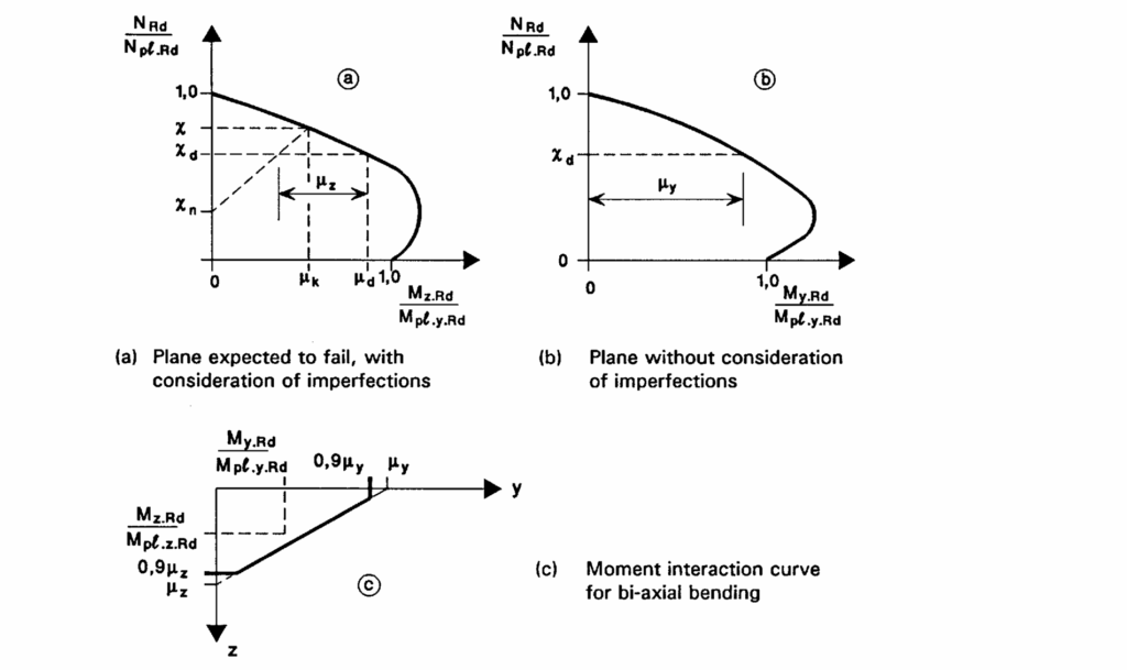
For a Column subjected to biaxial bending EC4 considers the check complete, when the following condition have been satisfied.
\frac{M_{Ed}}{\mu_y M_{pl,y,Rd}} +\frac{M_{Ed}}{\mu_z M_{pl,z,Rd}} \le 1.0Longitudinal & Transverse Shear
In general, the applied internal forces and moment from a member connected to the ends of a column are distributed between the steel section and the concrete of the composite section. EC4 requires that adequate provision have to be made for the distribution of these internal forces.
Axially loaded columns usually have sufficient interface shear, enough to develop the combined strength of both materials at the critical cross-sections. However, for columns resisting significant bending moment, a horizontal shear force is needed, which requires the development of longitudinal shear forces between concrete and steel. In similar fashion, transverse shear forces may be assumed to act, but on the steel section alone or on the steel and concrete section.
However, in practice it is unlikely that shear have any significant influence on the design of composite columns.
Worked Example
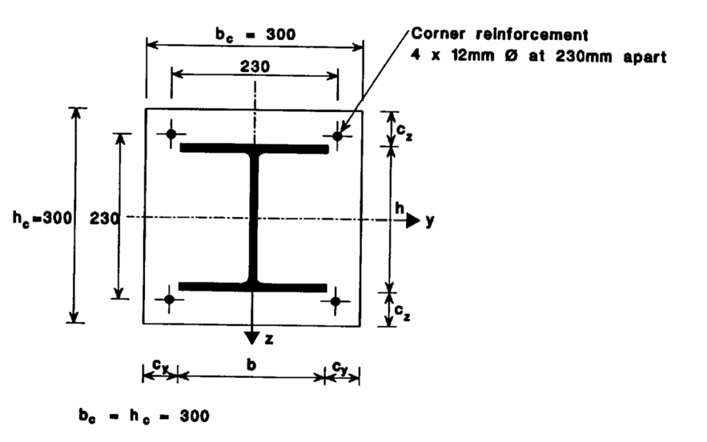
A 203 x 203 x 46UC is encased in a concrete section of 300mm x 300mm and reinforced with 4Y12mm bars in a new commercial development (Figure). If the column has an effective length of 4000mm in both axes, and the column is required to carry an axial load of 2200kN with no bending moment in both directions. Verify if the proposed composite section is adequate to sustain the estimated loads. Assuming the steel section is S355, concrete is C20/25 and reinforcing steel bars is 410Mpa.
Verify Buckling resistance of the Composite Section
The composite section is satisfactory if the following requirement is satisfied:
\frac{|N_{Ed}|}{min(\chi_y, \chi_z)N_{pl,Rd}}\le1To carry out the verification, we must determine the plastic resistance of the composite section to compression as well as the reduction factors about both axes.
Plastic resistance of Composite Section
Recall that the plastic resistance to compression Npl,Rd of a composite encased section is obtained by summing up the plastic resistances of the individual components. That is:
N_{pl,Rd}=A_af_{yd}+A_cf_{cd}+A_sf_{sd}Area of rebars – Using 4Y12mm Bars = 452mm2; Area of structural steel section = 5880mm2; therefore, area of concrete:
300\times300-5880-452=83668mm^2
N_{pl,Rd}=(5880\times355/1.05)+(83668\times0.85\times20/1.5)\\+452\times410/1.15 =3097kNReduction Factors
To determine the reduction factors; we must determine the non-dimensional slenderness about both axes and then apply the appropriate chart. The non dimensional slenderness is given as:
\lambda=\sqrt \frac{N_{pl,R}}{N_{cr}}N_{pl,R}=A_af_y+0.85f_{ck}A_c+A_sf_{sk}\\=3695kNN_{cr}=\pi^2\frac{(EI)_s}{l^2}The critical buckling load above will be determine for both axes. The flexural stiffness (EI)e in the formula is taken as the effective value; that is cognising the contribution of all materials that make up the composite section.
(EI)_e=E_aI_{a}+0.8E_{cd}I_y+E_sI_s(EI)_{ey}=21554kNm^2 (EI)_{ez}=15719kNm^2 N_{cr,y} =13296kN \quad N_{cr,z}=9696kN\lambda_y=\sqrt \frac{N_{pl,R}}{N_{cr,y}} =\sqrt \frac{3097.4}{13296} =0.53\lambda_z=\sqrt \frac{N_{pl,R}}{N_{cr,y}} =\sqrt \frac{3097.4}{9696} =0.621Using curve b for the major y-y axis and curve c for the minor z-z axis, the reduction factors are obtained as 0.87 & 0.77 respectively. Therefore, bending is more critical in the z-z axis
\frac{|N_{Ed}|}{min(\chi_y, \chi_z)N_{pl,Rd}} = \frac{2200}{0.77\times3097} = 0.92 \le1.0Therefore, the composite section performs satisfactory with respect to axial compression. If bending moments are applied, then the verification with respect to combined compression and bending needs to be carried out.
Also See: Designing a Composite Beam to Eurocode 4 | Worked Example
Sources & Citations
- Institution of Structural Engineers (2010) Manual for the Design of Structural Steelwork to Eurocode 3
- Steel Construction Institute P142: Composite Column Design to Eurocode 2
- Johnson R.P. and Anderson D. (2004) Designers’ Guide to EN 1994-1-1 Eurocode 4: Design of composite steel and concrete structures Part 1.1: General rules and rules for buildings, London: Thomas Telford