This article discusses the design of steel column splices in simple connection, for braced multi-storey buildings to Eurocode 3.
In braced steel frames, column design actions reduces as we go up the column stack. since there are no significant bending moment applied due to connection being simple and the typical load path in a structure is from top to bottom. Thus, in design of steel columns in braced frames, it is usually safe and conservative to size them using the maximum design values of the loads at the base level and adopts the same throughout the entire structure. This is however, sometimes impractical and uneconomical to do for a multi-storey arrangement. Hence the practice is to reduce column sections as we go up the structure specifically, where there is a significant reduction in the design loads. The connection between this column stacks of different section is referred to as a ‘Column Splice.’
In other words, column splices are essentially steel-plated bolted connection provided in multi-storey steel construction to serve as a connection between two columns of different stacks. While they are mostly utilized in connecting columns of different sections, a column Splice might be introduced even for column stack of same sections, perhaps to increase the ease of construction. For example, breaking a column into convenient lengths makes the fabrication, transportation and erection process very easy.
Column splices on each floor is seldom practiced because the savings in column materials is far-far outweighed by the cost of making a splice. Thus, they are typically provided with every two or three storey and are located just above the finished floor level.
Types of Column Splice
There are generally two types of steel column splice in braced steel frames. These are:
Bearing Splice
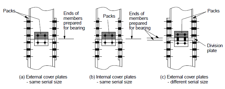
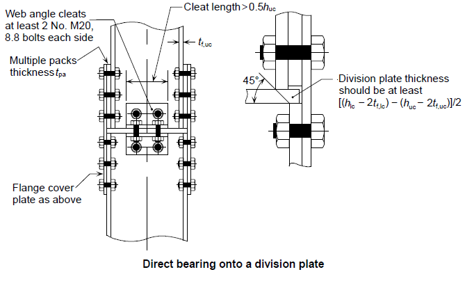
In a bearing type Splice connection, the actions are transferred by direct bearing, i.e. the upper column loads are transferred on the lower column directly, generally via the use of a plate known as a division plate or sometimes the ends of the members are prepared to bear on each other (See figure 1).
Non Bearing Splice
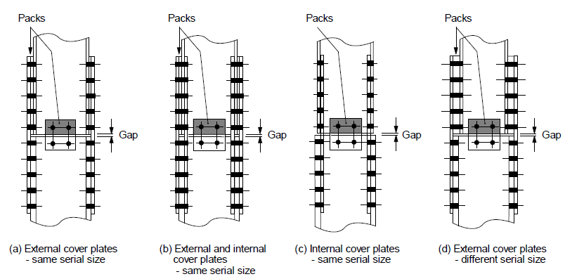
In a non bearing splice connection, loads are transferred via the bolts and splice plates. There is no bearing between the interconnected columns. They are usually detailed with a gap in between the column stacks (See figure 2).
The bearing type of splices are usually more simpler, having lesser bolts than non bearing splices, hence they are typically economical and thus commonly encountered in practice.
Detailing Requirement
In braced steel structures all joint must be detailed to remain a simple connection. In order words no joint should transmit significant moments. The detailing practice of column splices include the rules and practical considerations on fasteners, holes, fittings and geometry.
Fasteners
Generally the design of the fastener is in accordance with BS EN 1993-1-8. The fastener and spacing edge distance must comply with the rules giving below.
For majority of cases, M20 – M24 class 8.8 bolt should be sufficient for cover plates. Non preloaded bolts are normally used however, where preloaded bolts are used it is recommended that they’re designed as “non slip” resistant in accordance with the code requirement.
Fittings
Fittings are usually fabricated from S275 steel plates. If the splice is a bearing splice requiring a division plate it is necessary for it to be lightly welded to the column.
Holes
Holes are to be done in accordance with the laid down rules in BS EN 1090-2. They may be punched or drilled.
Geometry
As with all simple connections, there is a recommended geometry in order to ensure that the connection does not transmit a bending moment and remains a simple connection. In summary, the main objectives of detailing column splices are:
- Ensure that the connection is capable of transmitting the design forces
- Ensure all members are held accurately in position relative to each other
- Sufficiently rigid to ensure that the upper column stack remains in position during erection
- Provide nominal stiffness about both axes.
Design Requirement
The design of a bearing Splice involves checking the design forces and moments that
The design of a non-bearing Splice on the other hand is more involved and complicated. It requires all forces and moment to be transmitted through the bolts and Splice plates alone. Hence this would not be considered further in this post, a later post will attempt to explain the intricacies of a non-
The detailed design of a bearing Splice connection can be carried out in six steps. These are explained as follows.
Recommended Detailing Practice
The recommended detailing of column splices in bearing are rules based on past experience on column splices design. These guidelines are to be followed judiciously, in order to ensure the connection remain simple and do not transmit moment. This can be summarized in the following figures.
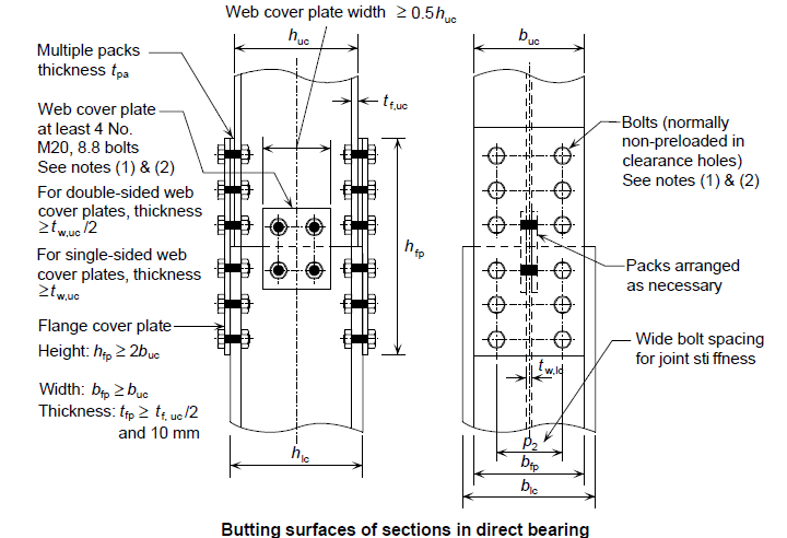
Note that the bolt spacings and edge distances are to comply with the recommendation of Table 3.3 of BS EN 1993-1-8.
Verify for Presence of Net Tension
The next procedure is to check the detailed splice connection for the presence of a net tension. Where a net tension does not occur, the splice is only detailed to transmit only axial compression through direct bearing. However, if a net tension does occur, then further checks on the endplates must be carried out.
For net tension to occur, the following expression must be satisfied
{ M }_{ Ed }>\frac { { N }_{ Ed,G }h }{ 2 } - MEd Is the column design moment at the floor level, below the splice
- NEd,G is the axial compressive force due to the factored permanent actions only
- h is conservatively the overall depth of the smaller column.
Verify Plates Resistance
Having checked for net tension in the plates, if a net tension does exist in the connection, the next step is to verify the plate resistance to the induced tensile stress. The following equation must be satisfied:
{ N }_{ Ed }\le { N }_{ t,Rd }{ N }_{ t,Rd }=min\left( { N }_{ pl,Rd } ; { N }_{ u,Rd } ;\ { N }_{ bt,Rd } \right){ N }_{ pl,Rd }=\frac { { A }_{ fp }{ f }_{ y,tp } }{ { \gamma }_{ M0 } } { N }_{ u,Rd }=\frac { { 0.9A }_{ fp,net }{ f }_{ u,tp } }{ { \gamma }_{ M2 } }{ \quad N }_{ bt,Rd }=\frac { { f }_{ u,tp }{ A }_{ fp,nt } }{ { \gamma }_{ M2 } } +\frac { { f }_{ y,fp }{ A }_{ fp,nv } }{ \sqrt { 3 } { \gamma }_{ M0 } }qWhere:
- Npl
,Rd is the tension resistance of thegross sectional area - Afp is the gross area of the flange plates attached to one flange
- Nu
,Rd is the tension resistance of the net area - Afp,net is the net area of the flange cover plates attached to one flange
Nbt ,Rd is the block tearing resistance for a concentrically loaded bolt group- Afp,
nv is the net section area subjected to shear Afp, nt is the net section area subjected to tensionfy ,tp is the plate yield tensile strength- fu
,tp is the plate ultimate tensile design strength
{ A }_{ fp,nv }={ 2t }_{ p }+\left( { e }_{ 1 }+\left( { n }_{ 1 }-1 \right) \right) { p }_{ 1 }\\-\left( { n }_{ 1 }-0.5 \right) { d }_{ o }{ A }_{ fp,nt } = { t }_{ p }\left( { p }_{ 2 }-{ d }_{ o } \right) \quad if\quad { p }_{ 2 }\le 2{ e }_{ 2 }={ t }_{ p }\left( { 2e }_{ 2 }-{ d }_{ o } \right) \quad if\quad { p }_{ 2 }>{ 2e }_{ 2}t f ,uc is the flange thickness of the upper column- bf,
uc is the flange width of the upper column - e1 & e2 are the edge and end distances of the plates
- do is the diameter of the holes
- n1 is a factor
- p1 & p2 are the bolt spacing of the plates
Where there is a significant net tension in the plates, preloaded bolts are to be used. The basic requirement for a significant net tension to exists in a Splice connection is defined here as :
{ N }_{ Ed }>0.1{ f }_{ y,uc }{ t }_{ f,uc }{ b }_{ f,uc }Verify Bolt Group Resistance
Once the check on the plate resistance to net tension is verified, the next step is to check the resistance of the bolt group. Where there is no net tension occurring in the plate this step can be skipped. The verification procedure depend on whether non-preloaded bolts or preloaded bolts are used.
Basic Requirement – Non Preloaded Bolts
{ N }_{ Ed }\le { F }_{ Rd,fp }{ F }_{ Rd,fp }=n{ F }_{ b,Rd }\quad if\quad { F }_{ b,Rd }\le { F }_{ v,Rd }\\ \quad \quad \quad \quad =n{ F }_{ v,Rd }\quad if\quad { F }_{ v,Rd }>{ F }_{ b,Rd }{ F }_{ b,Rd } =\frac { { k }_{ 1 }{ \alpha }_{ b }{ f }_{ u }d{ t }_{ p } }{ { \gamma }_{ M2 } } { F }_{ v,Rd }=\frac { { \beta }_{ p }{ \alpha }_{ v }{ f }_{ ub }A }{ { \gamma }_{ M2 } }- n is the number of bolts connecting one plate to a flange
- α= 0.6 for property class 8.8 bolts
- A is the tensile stress area of the bolt
- d is the diameter of the bolt
- do is the diameter of bolts holes including allowance
- tpa is the thickness of the bolt packing
{ \beta }_{ p\quad }=\quad \frac { 9d }{ 8d+3{ t }_{ pa } } \quad if{ \quad t }_{ pa }\ge \frac { d }{ 3 } \\ \quad \quad =1.0\quad if\quad { t }_{ pa }<\frac { d }{ 3 } { \alpha }_{ b } =min\left\{ \frac { { e }_{ 1 } }{ 3{ d }_{ o } } ;\frac { { p }_{ 1 } }{ { 3d }_{ o } } -\frac { 1 }{ 4 } ; \frac { { f }_{ ub } }{ { f }_{ u,fp } } ; 1 \right\} { k }_{ 1 } =min\left\{ 2.8\frac { { e }_{ 2 } }{ { d }_{ o } } -1.7 ;\ 1.4\frac { { p }_{ 2 } }{ { d }_{ o } } -1.7;\ 2.5 \right\}Refer to Clause 3.9.1 of BS EN 1993-1-8 for guidance on the procedure for verifying preloaded bolts. This refers to connections designed as non-slip under serviceability loads.
Verify Minimum Resistance of Cover Plate & Bolt Group
This check is required is required irrespective of whether a net tension occurs, it is the minimum resistance the cover plates and bolt groups are required to posses to ensure satisfactory performance.
For Cover Plate:
0.25{ N }_{ Ed }\le { N }_{ Rd } =\frac { { A }_{ fp }{ f }_{ y,fp } }{ { \gamma }_{ M0 } } For Bolt Group:
0.25{ N }_{ Ed }\le { F }_{ Rd,fp }- Afp is the area of flange cover plates
F Rd ,fp is the resistance of the bolt group as defined in the bolt group verification above
Verify Tying Resistance
Where it is required to comply with structural integrity requirement as its mostly the case, then the verification for plate and bolt resistances should be carried out using the value of NEd defined below
{ N }_{ Ed }=\frac { { N }_{ Ed,u } }{ 2 } NEd,u is the tensile force from BS EN 1991-1-7. However, it is usually conservative to adopt the values given from the plate and bolt verification.
Worked Example
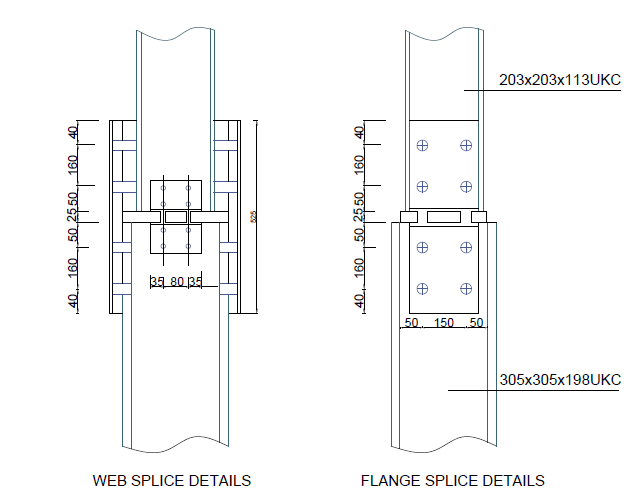
A column splice is required on the fourth floor of a multi-storey steel building to connect a 203x203x113UKC to a 305x305x198 UKC. The design actions and permanent factored actions just above the floor level are 1685kN and 1275kN respectively while the design bending moment is 55kN.m. Using the recommended detailing practice, design a splice connection completely.
Recommended Detailing Practice
1) Cover Plates:
height\quad ={ h }_{ fp }\ge 2{ b }_{ uc }+{ t }_{ db }width\quad ={ b }_{ fp }\ge { b }_{ uc }\\ =212.1\quad say\quad 250mm{ t }_{ fp }\ge max\left\{ \frac { { t }_{ f,uc } }{ 2 } ;\quad 10mm,\quad \frac { { p }_{ 1 } }{ 14 } \right\} =\frac { 16.3 }{ 2 } ;10;\frac { 160 }{ 14 } =\frac { 16.3 }{ 2 } ;10;\frac { 160 }{ 14 } \\=11.3\quad say\quad 12mm Packs,\quad { t }_{ pa }=\frac { { h }_{ lc }-{ h }_{ uc } }{ 2 } =\frac { 339.9-235 }{ 2 } =52.5mm\quad say\quad 30mm2) Division Plate
{ t }_{ wp }=\frac { \left[ \left( { h }_{ lc }-{ 2 }t_{ lc } \right) +\left( { h }_{ uc }-{ 2t }_{ uc } \right) \right] }{ 2 } = \left[ \frac { \left( 339.9-2( 36.4 \right) -\left( 235-2( 26.9 \right) }{ 2 } \right] \\=25.1mm\quad say\quad 25mm3) Web Cleats
Use\quad 90\times 90\times 8\quad angle\quad cleats\\ to\quad accomodate\quad M20\quad bolts
lenght\ge { 0.5h }_{ uc }=0.5\times 235\\=117.5mm\quad say\quad 150mmpacks\quad =\frac { { t }_{ w,lc }-{ t }_{ w,uc } }{ 2 } =\frac { 19.1-16.3 }{ 2 } =1.4mm\quad say\quad 2mm4) Summary of Splice Details
- Flange cover Plates: 2/250 x 12 x 525
- Flange packs: 2/250 x30 x 240
- Cleats: 4/90 x 90 x 8 Angles, 150mm long
- Web packs: 2/85 x 2 x 150
- Division plate: 265 x 25 x 310
- Bolts: M20 8.8
- Fitting material: S275 steel
Check for Net Tension
{ M }_{ Ed }=55kN.m\quad ;\quad { N }_{ Ed.G }=2275kN{ M }_{ Ed }=(55kN.m)\le \frac { { N }_{ Ed,G }h }{ 2 } =\frac { 1275\times 0.206 }{ 2 } =131.3kN.mSince there is no net tension occurring in the splice connection, thus we can ignore verifying the plate and bolt group resistance and just proceed to Check 5: Minimum cover plate & bolt group resistance.
Verify Minimum Cover Plate & Bolt Group Resistance
1) Cover Plates
0.25{ N }_{ Ed }\quad \le { \quad N }_{ Rd }\quad \\ 0.25{ N }_{ Ed }=421.25kN{ N }_{ Rd }=\frac { { A }_{ fp }{ f }_{ y,fp } }{ { \gamma }_{ M0 } } =\frac { 2\times 250\times 12\times 275 }{ 1.0 } \\=948.8kN671.25kN<948.8kN\quad o.k
2) Bolt Group
verify\quad that\quad { 0.25N }_{ Ed }\le { F }_{ pl,tp }{ F }_{ Rd,fp }=n{ F }_{ b,Rd }\quad if\quad { F }_{ b,Rd }\le { F }_{ v,Rd }\\ \quad \quad \quad \quad =n{ F }_{ v,Rd }\quad if\quad { F }_{ v,Rd }>{ F }_{ b,Rd }A) Shear resistance of a single bolt
{ F }_{ v,Rd }=\frac { { \beta }_{ p }{ \alpha }_{ v }{ f }_{ ub }A }{ { \gamma }_{ M2 } } { \beta }_{ p }=\frac { 9d }{ 8d+{ 3t }_{ pa } } =\frac { 9\times 20 }{ 8\times 20+3(30) } =0.72{ F }_{ v,Rd }=\frac { 0.72\times 0.6\times 800\times 245 }{ 1.25 } =68kNB) Bearing resistance of a single bolt
{ F }_{ b,Rd }=\frac { { k }_{ 1 }{ \alpha }_{ b }{ f }_{ u }d{ t }_{ fp } }{ { \gamma }_{ M2 } }{ \alpha }_{ b }=min\left\{ \frac { { e }_{ 1 } }{ 3{ d }_{ o } } ;\frac { { p }_{ 1 } }{ { 3d }_{ o } } -\frac { 1 }{ 4 } ; \frac { { f }_{ ub } }{ { f }_{ u,fp } } ; 1 \right\} \\ min \left\{ \frac { 40 }{ 3\times 22 } ;\frac { 160 }{ 3\times 22 } -\frac { 1 }{ 4 } ;1 \right\} =0.61{ k }_{ 1 } =min\left\{ 2.8\frac { { e }_{ 2 } }{ { d }_{ o } } -1.7 ; 1.4\frac { { p }_{ 2 } }{ { d }_{ o } } -1.7; 2.5 \right\} =min\left\{ 2.8\frac { 50 }{ 22 } -1.7; 1.4\frac { 160 }{ 22 } -1.7 ; 2.5 \right\} \\= 2.5{ F }_{ b,Rd }=\frac { 2.5\times 0.61\times 410\times 20\times 12 }{ 1.25 } \\=120kNSince the shear resistance of a single bolt is greater than the bearing resistance value, the minimum resistance of the bolt group would be governed by the shear resistance value and hence used for the calculation.
{ 2F }_{ Rd,tp }\quad =2\times n{ F }_{ v,Rd }=\\ 2\times 4\times 68\quad =544kN421.25kN<544kN\quad o.k
Having carried out all the required checks and the connection found to be satisfactory, the detailed connection as provided in figure 5 above can therefore be adopted.
See: Simple Connections in Multi-Storey Steel Frames
Sources & Citation
Steel Construction Institute (2014) Joints in Steel Construction: Simple Joints to Eurocode 3[Online]
Available at: www.tatasteelconstruction.com/ file_source/StaticFiles/Construction/p358.pdf, Ascot, Berkshire: SCI
buy generic tadalafil online – cialis generic pills can you buy cialis over the counter in uk
buy sildenafil 20 mg without prescription – brand viagra online canadian pharmacy viagra australia
cialis 6 – cialis online pharmacy tadalafil 50mg
stromectol online pharmacy – ivermectin 80 mg generic stromectol
casino world – real money casino games casino slot
ed pills that work – erectile dysfunction drugs male ed pills
canine prednisone 5mg no prescription – prednisone 6 mg 5 mg prednisone tablets
stromectol for humans for sale – stromectol buy nz ivermectin price usa
ed treatment drugs – best ed drug free samples of ed pills
Дом Гуччи 2021 смотреть онлайн
generic ventolin price – ventolin cost ventolin cost
онлайн бесплатно
where can i get cytotec pills over the counter – order cytotec cytotec sale singapore
doxycycline 100mg price australia – doxycycline cap price doxycycline 50 mg coupon
I think this is among the most vital info for me. And
i’m glad reading your article. But want to remark on few general things, The website style is ideal, the articles is
really nice : D. Good job, cheers
cheap neurontin online – buying neurontin online levothyroxine 75 mg coupon
http://buysildenshop.com/ – does viagra increase blood pressure
viagra stores – cost of viagra 100mg generic viagra professional
Levitra 10 Mg Italia
generic viagra online us pharmacy
Stromectol
Progesterone Website
can you buy cialis over the counter australia – cialis usa price
camp d’escalade sp cialis
Inhouse Pharmacy Australia
Viagra
vardenafil vs viagra – price of vardenafil order vardenafil online pharmacy
Propecia
Next Day Delivery Pharmacy
http://buystromectolon.com/ – Stromectol
Tomar Propecia Alopecia Androgenetica
https://buysildenshop.com/ – Viagra
ivermectin 6mg – ivermectin 0.5% ivermectin 18mg
tomar viagra sin receta medica
ivermectin tablets for sale
http://buystromectolon.com/ – ivermectin 3mg price
prednisone 10 mg – where to buy prednisone online online order prednisone 10mg no prescription
ad-scams.com is a fake scam website which is made up of fake comments more information here https://www.ad-scams.com
isotretinoin 30 mg – buy generic accutane 40 mg where can i get accutane cheap
смотреть
кино
buy amoxicillina 500 mg from mexico – amoxilin buy amoxicilin 500 mg online mexico
https://buysildenshop.com/ – taking viagra daily
Cialis
Propecia Coupon Manufacturer
How Levitra Works
medrol 4 pill – lyrica 250 mg lyrica 200 mg capsule
ivermectin side effects
sildenafil online – Buy viagra viagra citrate 150mg
gernic viagra
https://night-lady.co.il
cialis daily – Generic cialis tadalafil 10mg online india
http://buystromectolon.com/ – where can i buy stromectol in the usa
Небесная команда
Клятва врача
Злое
Воспоминание
Кэндимен
Propecia
http://buytadalafshop.com/ – generic name for cialis
https://buypropeciaon.com/ – finasteride (propecia)
9017
http://buytadalafshop.com/ – cialis cost
2190
8367
pro cialis 20 mg
https://bit.ly/3C36HHR
https://bit.ly/3C36HHR
https://bit.ly/3C36HHR
Форсаж 9 смотреть онлайн
Фильм Блогеры и дороги
https://bit.ly/2YBDdCz
https://bit.ly/2YBDdCz
Джой Американка в русском балете
https://bit.ly/2YBDdCz
ivermectin buy uk – buy ivermectin tablets stromectol price uk
http://buytadalafshop.com/ – Cialis
где фильм
https://bit.ly/38XeFWE
https://bit.ly/film-bestseller-2021-watch
https://bit.ly/film-bestseller-2021-watch
https://bit.ly/film-bestseller-2021-watch
https://bit.ly/38ZrjV1
https://bit.ly/3z36FOj
9988
furosemide online no prescription – furosemide 20 mg sales lasix 60