This article explores some common errors that can be encountered in finite element analysis of structures and some strategies to avoid them.
Finite Element Analysis (FEA) of structures is a numerical technique used to predict the behavior of complex engineering systems under various conditions. This powerful computational method finds application in structural engineering, mechanical engineering, and other disciplines for simulating how structures respond to loads, including forces, pressures, and thermal effects.
We cannot talk about how engineering software became a significant tool in engineering without mentioning finite element analysis. Engineers have always had ideas and concepts of complex structural systems, however, without the requisite method of solving the analysis problems required to birth the concepts, the concepts and ideas were simply cosigned to oblivion. However, things changed with the advent of finite element analysis in the 1940s. Many of the engineering problems engineers thought had no definite solutions have now been solved.
What is Finite Element Analysis?
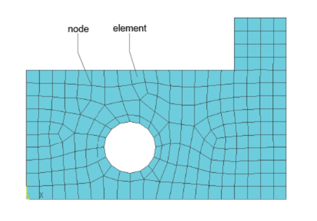
In FEA, a physical structure is divided into smaller, simpler elements, then mathematical models are applied to each element. These elements are interconnected at specific points called nodes, forming a mesh that represents the entire structure (Figure 1). The behavior of each element is analyzed using mathematical equations, taking into account material properties, geometry, and boundary conditions.
The governing equations for each of the elements are then combined to create a system of equations that represents the entire structure. These equations are solved using numerical methods to obtain the displacements, stresses, and other relevant information at each node in the mesh. Thus, the results obtained provide insights into the structural response, including deformations, internal forces, and possible failure points.
FEA allows engineers to assess the performance and safety of structures without physical prototyping, saving time and resources. It is widely used in the design and optimization of various engineering components, ranging from simple beams to complex aerospace structures. FEA can simulate diverse physical phenomena, including static and dynamic loads, thermal effects, and fluid-structure interactions.
However, despite its power, FEA requires careful consideration of various factors, such as mesh quality, boundary conditions, and material models, amongst other to ensure accurate and reliable results. Like any numerical technique, FEA is prone to errors that can compromise the accuracy of results. Thus, in this article, we will explore some common errors that can be encountered in finite element analysis of structures and some strategies you can deploy towards avoiding them.
Common Errors in Finite Element Analysis
The typical errors associated with other traditional methods of analysis such as improperly defined material, incorrect member size, inaccurate loading and so on can also be found in finite element analysis. However, there are certain errors that are more specific to finite element analysis. These errors can be sub-divided into two groups: Meshing errors and errors arising from incorrect boundary conditions. This article will focus on meshing and boundary errors as the former are more readily addressed.
Meshing Errors
Perhaps the biggest and the most prominent causes of error in 2D FEA models is meshing. Meshing is one of the fundamental steps in FEA. It is where the structure is divided into smaller analysis elements. Inaccurate meshing can lead to significant errors in results. Common meshing errors include:
Distorted Elements: Elements with highly distorted shapes can result in poor accuracy. Distorted mesh elements may lead to singularities and numerical instability. Ensuring that elements maintain reasonable aspect ratios and avoiding highly skewed shapes is very crucial.
Aspect Ratio: An excessively high aspect ratio of meshes (ratio of the longest side to the shortest side) can cause numerical instability and inaccurate results. Ideally, elements should have reasonably uniform aspect ratios to maintain solution accuracy.
Under-meshing: Using elements that are too large in regions with complex geometry or high stress gradients may result in an insufficient representation of the structural response. This can lead to inaccurate results, especially in areas with localized stresses or deformations.
Over-Meshing: Similarly, excessive mesh refinement presents no benefit. It leads to increase computational costs without a proportional improvement in accuracy. It can also introduce artificial stiffness and alter the behavior of the structure.
Abrupt Changes: Sudden transitions in element size or type can introduce errors. Gradual mesh refinement or coarsening is often preferred to ensure a smooth transition and accurate representation of the structural response.
Mesh Discontinuities: Failure to accurately capture material interfaces or structural changes can result in errors. Special attention should be given to meshing around regions with significant material inhomogeneity or geometric changes.
Mesh Sensitivity: The solution should be relatively insensitive to changes in mesh density. If the solution changes significantly with mesh refinement, it may indicate convergence issues or the presence of mesh-dependent errors.
How to Avoid Meshing Errors
In other to avoid meshing errors in FEA, here are some tips that may assist you:
Understand the Geometry: The first step towards addressing an error due to meshing in a FEA model is to first understand the geometry you’re working with. Having a good and thorough understanding of the geometry ensures that you can predict the critical regions of high stresses and identify places where a refined meshing will be required.
Choose an Appropriate Element Type and Order: Avoiding distorted shapes, excessive aspect ratio, under meshing or even over meshing is contingent on the order and element type used for the finite element analysis. Make sure to always choose the appropriate element type for your analysis (e.g. tetrahedral, hexahedral, or triangular elements). Different types have different accuracy and computational efficiency. Thus, an in-depth understanding of FEA is required to use FEA software.
Mesh Refinement: Understanding the geometry will help you to select the appropriate order and type of mesh required for an analysis. However, it is refinement that actually fixes any issue that may arise as a result of geometrical considerations. To obtain an accurate result, you must refine the mesh in critical regions, particularly in locations where high gradients or complex stress distributions are expected. Adaptive meshing techniques are available today in many FEA software today, that can help you.
Use Quality Meshing Software: Lastly, addressing meshing errors is impossible if you use a very prohibitive software that does not give you control over the aforementioned solutions. Thus, it is very important to invest in high-quality FEA software that allows for easy control over mesh size and refinement. A very good FEA software packages will often come with robust meshing capabilities.
Incorrect Boundary Condition
The second class of common errors found in finite element analysis result from an engineer applying an incorrect or unrealistic boundary condition to an FEA model.
Since finite element analysis is a numerical method of analysis, it follows that boundary conditions must be applied to arrive at a definite outcome. However, applying an incorrect boundary condition will only produce an unrealistic analysis outcome and misinterpretations of the actual structural behaviour. Some of the common errors typically encountered in FEA due to incorrect boundary conditions include:
Incomplete Constraints: The laws of statics are always right! Failing to adequately constrain all degrees of freedom would only lead to rigid body motions, resulting in unrealistic deformations and stress distributions. It is crucial to ensure that all restraints are applied to prevent unintended structural deformation.
Over constraint: Applying excessive constraints can lead to over constraint issues, causing singularities, convergence problems, and inaccuracies. Careful consideration and validation of applied constraints are essential to avoid unnecessarily restricting the system.
Incorrect Constraint Types: Choosing the wrong type of constraint for a specific problem, such as fixing a degree of freedom that should deform or applying an incorrect support type, can yield inaccurate results. Precision in selecting and applying constraints is crucial.
Dependency on Reaction Forces: Relying solely on reaction forces for constraints without considering the equilibrium of internal forces can introduce errors. Proper understanding of the structural response involved, and realistic application of constraints are necessary for accurate analysis results.
Inconsistent Mesh and Boundary Conditions: Finally, inconsistencies between the mesh and applied boundary conditions can lead to errors. Ensuring proper alignment of the mesh with the geometry and consistent application of boundary conditions to corresponding nodes and elements is essential for accurate FEA results.
How to Avoid Incorrect Boundary Conditions
Addressing boundary condition error in a finite element model requires the engineer to consider the following:
Thorough Understanding of the System: First of all, gain a comprehensive understanding of the physical system you want to model. This includes recognizing expected behaviors, critical loading conditions, and the appropriate constraints required for an accurate analysis result.
Complete and Consistent Constraints: Ensure that all degrees of freedom are adequately constrained. Incomplete constraints will only lead to rigid body motions and inaccuracies as aforesaid. Additionally, maintain consistency between the mesh and applied boundary conditions, ensuring that constraints are appropriately applied to corresponding nodes and elements.
Avoid Over constraint: Be cautious not to over constrain the system by applying excessive constraints. Over constraint would cause convergence issues and thus, inaccurate results. Carefully validate and select the minimum set of constraints necessary to accurately represent the structural problem.
Correct Constraint Types: Choose the correct type of constraint for each situation. Understand the differences between fixed supports, roller supports, etc. Applying the wrong type of constraint would only introduce errors into the results.
Regular Validation of Results: Regularly validate FEA results against known analytical solutions, empirical data, or rules of thumbs. Consistent validation helps ensure that the chosen boundary conditions are appropriate and representative of the structural system.
See: Top 10 Structural Engineering Software of 2023
Conclusion
Despite its power, Finite element analysis requires careful consideration of various factors, such as mesh quality, boundary conditions, material, loading, geometric parameters amongst other to ensure accurate and reliable results.
In structural engineering, Finite Element Analysis (FEA) is a valuable tool, but its effectiveness relies on accurately representing the structural system and carefully considering all factors that affect results. To enhance the reliability of FEA model results, engineers must keep an eye on the common errors detailed in this article. And in addition to the steps listed for avoiding these errors, engineers should ensure that they validate their models against the conservative, less rigorous analytical analysis methods, and stay updated with advancements in FEA.