This article explores the prevalent of light gauge steelwork in steel construction today. It covers their applications, design considerations and structural integrity considerations when specifying them in constructions.
Light steel framing today, have become very popular and is a favored choice across diverse steel applications. Not just serving only as secondary steelwork but also assuming the role of primary load-bearing components. Its utilization in construction is attributed to the slender gauge of cold-formed steel, which imparts lightweight properties but also renders it susceptible to localized buckling.
Due to the foregoing, designing entails a focus on effective section properties, a departure from conventional practices observed in hot-rolled members. In fact, the industry emphasizes the importance of certification schemes to guarantee compliance of cold-formed steel products with contemporary standards, ensuring their reliability and performance in various structural applications.
This article explores the prevalent of light gauge steel-work in certain construction today. It covers their applications, design considerations and structural integrity considerations when specifying them in constructions.
Light Guage Steel Sections
Light steel members are typically fashioned through cold-forming techniques from hot-dip galvanized strip steel, supplied to section manufacturers in the form of pre-galvanized coils with varying thicknesses, typically ranging from 0.9 to 3.2mm. The standard zinc coating, designated as Z275 for construction products, signifies a zinc content of 275 grams per square meter spread over both surfaces of the steel strip. In light steel framing applications, prevalent steel grades include S350, S390, and S450, with S390 and S450 being commonly employed for purlin and sheeting rail products. Light steel framing typically adopts a lipped C section shape with depths ranging from 70 to 250mm, while purlins are often crafted from Sigma or Zed sections, typically 140 to 300mm deep.
Applications of Light Guage Steel Work
The utilization of light gauge steel in steel frame construction offers a multitude of possibilities, each brimming with active potential. Some of the most popular applications are presented and briefly expounded upon in the ensuing sections.
‘Stick-Build’ Construction
This approach involves the on-site assembly of discrete members to erect load-bearing walls, floors, and bracing systems. Components are typically delivered pre-cut and pre-punched, with on-site connections facilitated by self-drilling screws, bolts, or other site-specific techniques. Though labor-intensive compared to other methods, ‘stick-build’ construction proves invaluable in intricate projects where prefabrication is less viable.
Infill Wall Construction
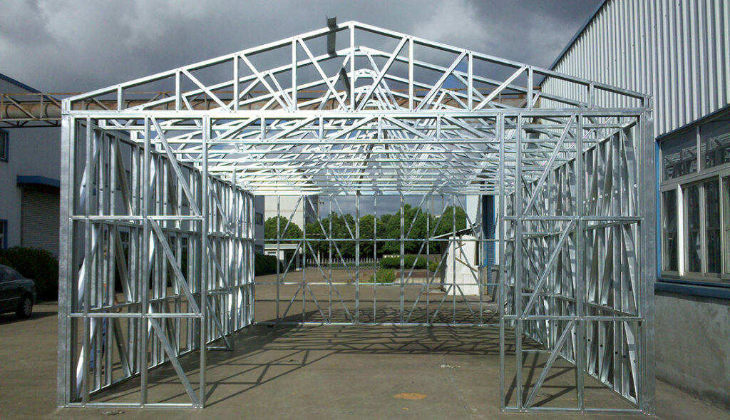
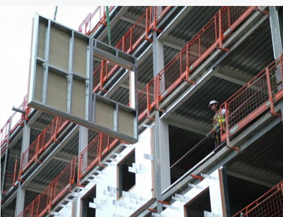
These external walls, situated between the floors of a building’s primary structural frame, serve to bolster the cladding system and withstand wind loads. Precision-cut C section studs are individually installed, with top and bottom ‘tracks’ designed to deflect without transferring load to the stud. Infill wall panels may also be prefabricated and crane-installed, as depicted in Figures 1.
Panel Construction
Two-dimensional assemblies like wall panels, floor cassettes, and roof trusses can be prefabricated and assembled on-site, with potential finishing touches applied in the factory to expedite on-site work. The geometric accuracy and reliability of such panels exceed those of ‘stick-build’ counterparts due to off-site manufacturing.
Modular Construction
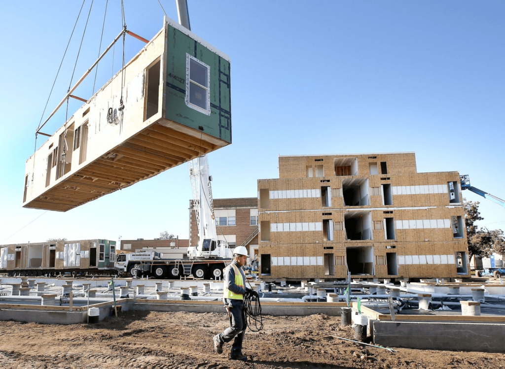
Three-dimensional units, serviced and finished in the factory, offer enhanced quality and thermal performance. Modules (Figure 2), either load bearing or supported by corner posts and edge beams, may be stacked or arranged side by side to form the final structure. Stability is ensured through bracing, while sheathing boards may enhance wind stability and weather-tightness during assembly.
Hybrid Construction
In certain scenarios, a fusion of construction methods proves advantageous. For instance, bathroom pods may complement a stick-built light steel frame, or light steel residential units may sit atop a hot-rolled steelwork podium.
Secondary Steelwork
Light gauge steel sections also find widespread use as secondary steelwork in hot-rolled steel frames, providing not only cladding support but also lateral restraint to primary steelwork in portal framed constructions.
Design Considerations
To ensure the structural soundness of a selected section, it must undergo verification as per the guidelines outlined in the applicable code of practice. Specific regulations governing light steel sections can be located in BS EN 1993-1-3 (EC3 Part 1-3). Within the Eurocode framework, designers have the flexibility to validate members through either calculations or testing.
Design by Testing
Adopting a design approach centered on testing can yield structural members that are lighter compared to those determined through calculation. However, this method is practical only for standardized systems that are mass-produced, given the expenses associated with conducting physical tests in accredited laboratories. Manufacturers of purlins and side rails utilize testing to establish member resistances across various section dimensions, subsequently publishing these findings in load/span tables for utilization by structural designers.
Design by Calculation
Designing by calculations remains the preferred choice among designers of light steel frames and floor joists. In light steel design, the initial step involves assuming section classification as Class 4 in accordance with EC3 Part 1-12. The determination of effective section properties follows the same protocols for design resistance as delineated in EC3 Part 1-1. Nevertheless, addressing core steel thickness, employing mid-line theory, and considering the influence of corner radii are critical factors when contemplating light steel sections:
Core Steel Thickness
When determining the steel thickness, it’s customary to include the coating thickness in the specified value. However, EC3 Part 1–3 (Clause 3.2.4) mandates that all section properties should be based on the core thickness of the steel, excluding any coating. Consequently, for design considerations, the specified steel thickness needs to be decreased by 0.04mm — which corresponds to the standard zinc coating (Z275) utilized in construction products.
Mid-Line Theory and Corner Radii
In computing section properties, it’s standard to measure all dimensions along the mid-lines of the individual elements. This practice leads to a reduction in the element length below its nominal value, either to t/2 or t, depending on the number of corners.
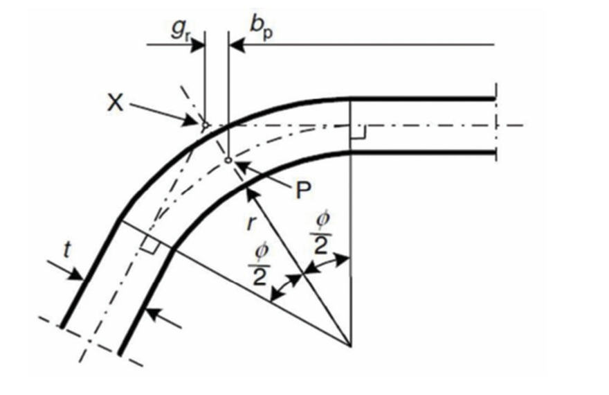
According to mid-line theory, the intersection of the web and flange occurs at point X, where the two mid-lines converge, while the actual intersection point is P, a distance gr from X. Any section properties derived from mid-line theory won’t be precise, and the Eurocode provides guidance on the significance of this error (Figure 5). EC3 Part 1–3 specifies that the impact of rounded corners on cross-section resistance may be disregarded, provided the corner radius falls within the limits outlined in the Eurocode.
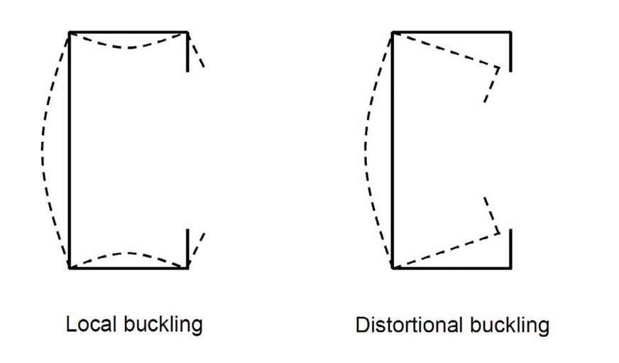
Local and Distortional Buckling
A very important design consideration when specifying light-gauge steelwork is their tendency to undergo local and distortional buckling under load. Thus, when designing them local buckling needs to be checked.
When addressing local buckling in light gauge steelwork, one may approximate the behavior of the member by using the effective width method. This method results in a simplified model where a uniform stress, equivalent to the yield strength of the steel, is assumed to act over a reduced width of the plate. EC3 Part 1-3 employs the effective width concept for each section element; thus, an effective width is computed for all elements experiencing compressive stress. Since the distribution of compressive stress varies across sections subjected to pure axial compression versus those subjected to bending, it’s evident that the effective section properties will differ between these scenarios. Hence, it’s crucial to utilize the relevant effective properties for the specific case under consideration.
When contemplating local buckling, it’s assumed that the corners of the section remain fixed, allowing the buckling deformation to occur within the element’s length. This scenario is depicted in Figure 4 (left). Conversely, Figure 4 (right) illustrates a situation where the right-hand corners of the flanges are not fixed, permitting the flanges to rotate, known as distortional buckling.
The susceptibility of a section to distortional buckling hinges on the stiffeners’ (lips’) ability to restrain displacement of the adjacent flange corners. This is contingent upon the geometry of the stiffeners relative to the flanges and, notably, their relative stiffness.
Guidance for designing plane elements with edge or intermediate stiffeners is outlined in Clause 5.5.3 of EC3 Part 1-3. The advice provided in the Eurocode integrates the calculation of effective width (considering local buckling within the element’s length) with the computation of a reduced thickness for the stiffener, accommodating the impact of distortional buckling.
Structural Integrity
Because light gauge steelwork is made up of cold-formed steelwork that are essentially even lighter compared to hot-rolled section, their structural integrity is of utmost concern when specifying them. Three considerations are apt here. Frame stability and anchorage, structural robustness and fire resistance.
Frame Stability and Anchorage
Ensuring the stability of light steel framing typically involves employing integral bracing, cross-bracing, or relying on diaphragm action. Integral bracing entails placing C section members diagonally between vertical wall studs and within their depth. Unlike integral bracing, each cross-bracing element operates solely in tension, necessitating the crossed arrangement. Crossed flat straps affixed to the face of vertical studs extend across multiple studs and should be securely attached to each stud they intersect.
If the designer opts to depend on the racking resistance of the wall itself, stability is achieved through diaphragm action within the wall plane due to the attached board or cladding. Various board options, such as plywood, cement particle board, and oriented strand board (OSB), can be utilized.
The racking resistance of a specific board and frame combination should be determined through testing. To prevent sliding, overturning, or lifting off the foundations, light steel framed buildings must be adequately anchored using a suitable anchorage system. Generally, two types of anchorage are employed: holding down bolts connecting the stud and track to the ground slab, and steel straps connecting wall studs to the foundations.
Robustness
The guidelines for meeting robustness requirements, as outlined in BS EN 1991-1-7, are independent of material. Light steel framing-specific guidance is provided in the UK National Annex, specifying that minimum horizontal tie forces for lightweight building structures should be 15kN for internal ties and 7.5kN for perimeter ties.
Light steel multi-storey structures are typically structurally robust due to their construction involving a large number of regularly distributed structural elements with a high level of connectivity. Ensuring continuous ties between components is generally straightforward due to multiple interconnections. However, connection resistances must be verified to meet appropriate requirements.
For modular buildings, robustness is achieved through ties between modules. Tying action, illustrated in, assumes a minimum tying force equivalent to half the loaded weight of the module, with a recommended minimum tie force of 30kN.
Fire Resistance
Typically, fire protection for light steel elements involves one or two layers of plasterboard or similar material (three layers for fire resistance periods exceeding 90 minutes). Various types of board materials are used in light steel construction, each providing different levels of protection. Fire-resistant plasterboards (Type F to BS EN 520) are designed to offer specific levels of fire protection, with fire resistances ranging from 60 to 120 minutes being readily achievable.
Light gauge steel construction is designed to resist potential fires originating inside the building. However, in some cases, protection from external fires must also be considered. The fire resistance period for a given wall construction will differ for internal and external exposures.
Also See: Designing a Composite Slab to Eurocode 4| Worked Example
Sources & Citations
- Steel Construction Institute (2014) Light Steel Forum [Online] Available at: www.lightsteelforum.co.uk (Accessed: August 2014)
- Institution of Structural Engineers (2014) ‘Light Guage Steelwork’ Composite and Steel Construction Compendium. The Structural Engineer 95(9).