This article explores what structural engineers must know about below-ground drainage. It draws directly from the IStructE Technical Guidance Note (Level 1, No. 34), offering deeper insights and practical advice.
Drainage systems rarely feature in the spotlight during structural design discussions. Yet when things go wrong, their consequences ripple through foundations, walls, and even structural reputations. Poor drainage causes more long-term structural problems than visible design errors. It creeps in silently, damaging finishes, corroding steel, and softening soils beneath critical footings.
This article explores what structural engineers must know about below-ground drainage. It draws directly from the IStructE Technical Guidance Note (Level 1, No. 34), offering deeper insights and practical advice. It is not a substitute for the note. But a supplement—between guidance and construction facts.
Too often, structural engineers treat drainage as someone else’s problem. That attitude has caused unnecessary failures in walls, basements, suspended slabs, and ground-bearing floors. The irony is painful: we design for strength and deflection but forget water is patient. It will always find a weakness, and when it does, the entire structure suffers.
Understanding Why It Matters
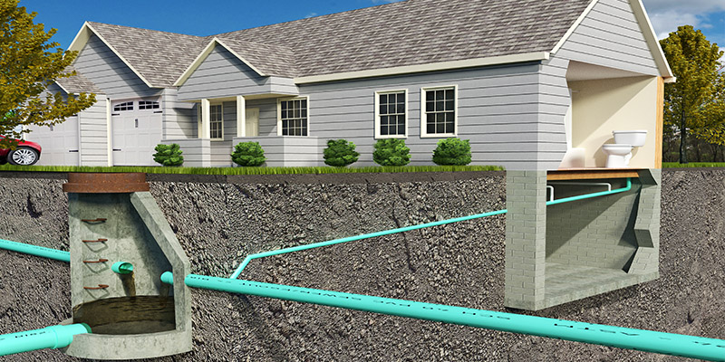
Drainage carries away more than water. It carries risk. Without proper routing, water saturates soils, changes load paths, and undermines ground stability. A single failed drain can lead to differential settlement beneath column bases. It can allow rising damp into structural walls, degrading concrete and rusting reinforcements.
Groundwater behaves differently across sites. On sloped terrain, it moves quickly. On clayey plains, it sits and rises. Drainage controls both behavior and consequence. When ignored, even well-designed foundations perform poorly. This often happens not due to a design flaw in the structure, but a silent failure in water management.
In structural failure investigations, drainage issues have ranked high. Misaligned pipes, crushed bedding, and absent traps create soil voids and base erosion. Foundation performance then changes over time, appearing first as cracks, then as differential tilt. In many cases, these are mistaken for design errors when they are really drainage problems.
The Fundamentals of Drainage Design
Every drainage system has two basic purposes: to convey water and to do it without damaging anything else. To meet those purposes, structural engineers must understand two principles—hydraulics and compatibility. Hydraulics ensures the water moves fast enough to clear solids. Compatibility ensures the pipes don’t compromise the soil, the structure, or themselves.
Water in drainage systems behaves under gravity. For it to keep moving, the gradient must be sufficient. Too steep, and solids settle. Too shallow, and flow stalls. For most applications, gradients between 1:40 and 1:80 are safe. These are not just civil concerns. Pipes pass through footings, floor slabs, and sometimes beams. Structural details must accommodate those gradients and allow clearance and fall.
Pipe sizing depends on population and purpose. Rainwater pipes may carry sudden volumes. Foul drains carry regular, slower flows. But both must meet a minimum self-cleansing velocity—often around 0.75 m/s. This isn’t a trivial number. If flow slows, solids settle. If solids settle, pipes block. And If they block, water backs up into basements and wall cavities.
Pipe Types and Structural Impact
Four main pipe types exist: uPVC, HDPE, vitrified clay, and concrete (Figure 1). Each behaves differently when buried, loaded, or misaligned. Engineers often ignore these differences until it is too late. A uPVC pipe, for example, is lightweight and easy to cut, but can deform under load if bedding is poor. Clay pipes resist chemicals but are brittle under impact. Concrete is strong but heavy and porous unless sealed.
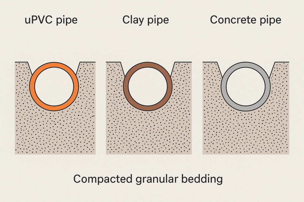
The choice of pipe material affects everything: trench depth, bedding, joint type, flexibility, and compatibility with structural elements. Structural engineers must know what passes under suspended slabs or cuts through strip footings. Ignoring pipe stiffness leads to cases where slab movement crushes pipes or misalignment causes joints to leak.
Drainage Trenches: Hidden Structural Hazards
Drainage trenches weaken soils. That sounds obvious, but many engineers forget how deep, linear excavations change load paths. A narrow trench beneath a load-bearing wall behaves like a weak spot. If backfilled poorly, it settles. If backfilled stiff, it becomes a hard spot that causes differential heave. Neither is acceptable.
Structural drawings often fail to show trench profiles. Contractors, unaware of live loads above, dig without care for bearing capacity. Pipes end up in loosely compacted gravel. Compaction above the pipe gets skipped to avoid damage. Months later, the trench settles. Cracks appear in the floor. Blame goes everywhere.
Engineers must provide trench backfill specifications. These include bedding thickness, compaction level, and material type. Without clear notes, contractors guess. Where trenches cross structural footings, reinforcement bars should bridge them. This ensures the foundation behaves as one unit, not as interrupted segments.
Connections through Walls and Slabs
Drains must penetrate structures, but penetrations are weak spots. If not sleeved properly, they cause cracks and allow water ingress. A pipe passing through a wall without a sleeve moves independently. This leads to shearing of either the pipe or the wall over time. The solution is simple: embed pipes inside oversize sleeves with compressible filler.
Slabs present more complex challenges. Pipe locations must be coordinated with rebar and formwork. If ignored, installers cut rebar or shift pipe runs off-gradient. Neither should happen. These conflicts start with design. Engineers must provide pipe zones. Architects must match these with plumbing drawings. And site supervisors must enforce them.
Pipes embedded in slabs must remain accessible. This means installing inspection chambers, vertical stacks, or access points nearby. Engineers must not assume that a buried pipe will never fail. Experience proves otherwise.
Image suggestion: A slab plan showing a designated pipe corridor with rebar detailing around sleeves.
Foul and Surface Water Separation
Combining foul and surface water drainage is a historical mistake. Modern codes require separation, but site practice still mixes them in places. This causes overloading during rain and backflow of waste in low-pressure areas. For structures with basements, the result can be catastrophic.
Surface water drains must handle rapid inflow. Roof gutters, external yards, and paved areas must channel rain to soakaways, swales, or main drains. Foul systems, on the other hand, move slower and carry solids. Mixing both leads to siphoning of traps and foul air entering buildings.
Structurally, mixed systems create pressure surges during storms. These lift manhole covers, collapse lightweight pipe sections, and displace weak joints. The fix is separation. And the responsibility rests with the engineer. At the very least, engineers must verify the pipe system matches the site drainage plan and layout.
Common Construction Mistakes
Construction sites are fast-paced. That makes drainage a prime candidate for shortcuts. Common errors include shallow trenches, reversed gradients, incomplete joints, and skipped bedding. These aren’t just contractor issues. They stem from design vagueness and inspection failure.
One major mistake is allowing pipe falls to exceed 1:20. This sounds efficient, but water outruns solids at high speed. Over time, solids settle and harden. Flow stops. Blockages follow. Another mistake is using sharp changes in direction without manholes. Every change should be accessible. Otherwise, failures become invisible until too late.
Some engineers neglect soil movement. On expansive clays, drain pipes must accommodate differential settlement. That means using flexible couplings, extra sleeves, or compensating joints. On sandy soils, trench collapse during backfill is a real risk. The solution lies in specifying trench side support and backfill staging.
Testing and Certification
Before handover, all drainage systems must be tested. The process involves air or water tests. These detect leaks, joint failures, and low points. But many projects skip this step. Once a slab is poured or a trench is covered, failures become invisible.
Air testing involves sealing both ends of a pipe run, applying pressure, and watching for drops. Water tests involve filling the system and checking for steady levels over time. Structural engineers must specify which test applies and when to conduct it. They must also inspect before backfilling.
Inspection chambers must be tested, sealed, and made watertight. If covers sit below ground level, they must include flood-proofing and venting. And all test results should be part of the structural completion file. Without this data, future claims become impossible to defend.
Conclusion
Below-ground drainage isn’t a specialist’s concern alone. It is a structural engineer’s responsibility. Every foundation, slab, and wall depends on dry, stable soil. Without effective drainage, no structure performs as designed. Failures may appear slow, but they accumulate relentlessly.
This article has shown that drainage systems are more than pipe networks. They are part of structural performance. They affect ground behavior, support durability, and influence maintenance. Ignoring them is not just negligent. It is unprofessional.
Engineers must lead this change. By including drainage design in our scope and checking it during construction, we protect both structures and reputations. Let others call it a civil task. We know it’s a structural necessity.
Also See: Steel Fibre Reinforced Concrete Ground Bearing Slab | Worked Example
Sources & Citations
- Institution of Structural Engineers. (2014). Technical Guidance Note: Introduction to Below-Ground Drainage (Level 1, No. 34).
- British Standards Institution. (2019). BS EN 752: Drain and Sewer Systems Outside Buildings.
- CIRIA. (2001). Control of Water Pollution from Construction Sites: Guidance for Consultants and Contractors (C532).
- Building Research Establishment. (2007). Good Building Guide 42: Installing and Testing Drainage Pipes.