This article explores the theorem’s theory, its application in structural engineering, and a worked example involving a steel truss.

In structural engineering, analyzing and designing structures requires precise calculations of forces, stresses, and rotational properties. The Parallel Axis Theorem plays a pivotal role in determining rotational inertia, especially when dealing with components not aligned with their centroidal axes. Structural systems like trusses, beams, and frames often involve members that experience moments about axes that are not centered. This is where the theorem becomes essential, as it simplifies the process of computing moments of inertia for these cases.
Structural engineers use the Parallel Axis Theorem to assess stiffness, stability, and load distribution in various structures. When analyzing steel trusses or reinforced concrete beams, the theorem enables the calculation of critical parameters that influence behavior under loading. This facilitates the optimization of our designs, ensuring safety and efficiency. For instance, during the design of bridge girders, engineers use this theorem to determine resistance to bending and torsion forces.
Applications of the Parallel Axis Theorem extend to wind and seismic load analysis in high-rise buildings, where structural components experience forces away from their centroidal axes.
This article explores the theorem’s theory, its application in structural engineering, and a worked example involving a steel truss.
Moment of Inertia
The moment of inertia (I) measures a body’s resistance to rotational motion about a specific axis. In structural engineering, it determines how a member responds to bending moments. For beams, trusses, or columns, knowing the moment of inertia is essential for evaluating deflection, stability, and load-resistance capacity.
For an element with a non-centroidal axis, directly calculating the moment of inertia can be complex. The Parallel Axis Theorem simplifies this by linking the moment of inertia about any axis to the moment of inertia about a centroidal axis. This connection enables engineers to compute rotational properties for structural members with off-center axes efficiently.
The Parallel Axis Theorem
The Parallel Axis Theorem states:
I_{axis}=I_{cm}+Ad^2Where:
- Iaxis = Moment of inertia about the specified axis
- Icm = Moment of inertia about the centroidal axis
- A = Cross-sectional area of the member
- d= Perpendicular distance between the centroidal axis and the specified axis
The theorem assumes that the structural member remains rigid and uniform, conditions generally satisfied in practical engineering materials like steel and concrete.
Derivation of the Parallel Axis Theorem
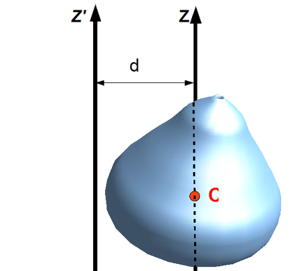
The derivation assumes the mass distribution of the body is defined relative to two axes: the center of mass axis (z′) and the desired parallel axis (z) (Figure 1). The derivation involves integrating the mass distribution relative to a shifted axis. For a rigid structural member:
Let the coordinates of the center of mass be (xcm and ycm). For a rigid body, the center of mass is defined such that:
\int x \cdot dm =x_{cm}\cdot M\int y \cdot dm =y{cm}\cdot MShift the reference frame so that the new axis (z) is parallel to ‘z′, separated by a perpendicular distance d.
If we rewrite the moment of inertia about the z axis:
I_{axis}= \int[(x+d)^2+y^2]\cdot dmIf we expand and separate the terms
I_{axis}=\int (x^2+2xy+d^2+y^2)\cdot dmThe first term, ∫x2+y2 dm, is Icm. The second term, ∫2xd dm vanishes because x is measured from the center of mass, where ∫x dm=0. The third term becomes d2∫dm=Md2= Md2
Therefore:
I_{axis}=I_{cm}+Ad^2Applications in Structural Engineering
Trusses
Trusses are integral to structural systems, providing stability and support for roofs, bridges, and towers. Steel trusses, composed of top chords, bottom chords, and web members, experience moments due to applied loads. For accurate analysis, engineers calculate the moments of inertia about specific axes, often not aligned with the centroid.
Using the Parallel Axis Theorem, engineers determine moments of inertia for both individual members and the overall truss system. This enables them to predict deflections, assess stability, and optimize material usage.
Beams and Girders
In beams and girders, the moment of inertia governs resistance to bending and deflection under loads. The Parallel Axis Theorem allows engineers to compute the inertia for sections with offset axes, such as flanged beams or I-sections subjected to eccentric loading.
Wind and Earthquake Load Analysis
High-rise buildings must withstand dynamic forces like wind and seismic loads, which induce rotations about axes away from the centroid. By applying the Parallel Axis Theorem, engineers calculate the rotational stiffness and design lateral load-resisting systems that ensure structural integrity.
Worked Example
A steel truss consists of two primary chords: a top chord measuring 200 mm wide and 20 mm thick and a bottom chord measuring 150 mm wide and 20 mm thick. The vertical distance between the top and bottom chords is 1 meter, and the overall length of the truss is 5 meters. Determine the moment of inertia of the truss about its centroidal axis and a secondary axis passing through the bottom chord, utilizing the Parallel Axis Theorem.
Step 1: Identify Cross-Sectional Areas and Centroid
For the top chord:
A_{top}=200\times20=4000mm^2Centroidal distance from the bottom chord:
d_{bot}=1000mmSimilarly for the bottom chords
A_{bot}=150\times20=3000mm^2d_{top}=0mmStep 2: Determine the Combined Centroid
The location of the combined centroid (ycm) is calculated using the weighted average formula:
y_{cm}=\frac{\Sigma A\cdot y}{\Sigma A}Substitute the values:
y_{cm}=\frac{(4000\times1000)+(3000\times 0)}{4000+3000} =571.3mmStep 3: Compute Moment of Inertia (Icm) for Each Member
Top Chord
The distance from the centroidal axis is:
d_{top}=1000-571.3=428.7mmMoment of inertia about the centroidal axis:
I_{top}=\frac{1}{12}A_{top}b^2+A_{top}d_{top}^2I_{top}=\frac{1}{12}(4000\times200^2)+(4000\times 428.57^2) =8.7\times10^8mm^4Bottom Chord
The distance from the centroidal axis is:
d_{top}=571.3mmMoment of inertia about the centroidal axis:
I_{top}=\frac{1}{12}A_{top}b^2+A_{top}d_{top}^2I_{top}=\frac{1}{12}(3000\times150^2)+(4000\times 571.43^2) \\=10.36\times10^8mm^4Step 4: Compute Total Moment of Inertia
The total moment of inertia about the centroidal axis is:
I_{total}=I_{bot}+I_{top}=1.9\times10^9mm^4Step 5: Moment of Inertia About Bottom Chord Axis
Using the Parallel Axis Theorem, the moment of inertia about the bottom chord axis is:
I_{bot}=I_{cm}+A_{top}d^2I_{bot}=1.9\times10^9+4000\times(1000)^2 \\=5.9\times10^9mm^4Conclusion
The Parallel Axis Theorem simplifies rotational property calculations for structural components with axes away from their centroid. This example demonstrates its application to a steel truss, highlighting the accuracy and practicality of the theorem in structural engineering.
See: A Simplified Method of Estimating Deflection in Trusses
Sources & Citations
- Gere, J. M., & Goodno, B. J. (2012). Mechanics of Materials (8th ed.). Cengage Learning.
- Zienkiewicz, O. C., Taylor, R. L., & Zhu, J. Z. (2013). The Finite Element Method: Its Basis and Fundamentals (7th ed.). Engineering Structures, 56(2), 211–230. https://doi.org/10.1016/j.engstruct.2012.07.004
- American Institute of Steel Construction (AISC). (2017). Steel Construction Manual (15th ed.). American Institute of Steel Construction.
- Khan Academy. (n.d.). Moment of Inertia and the Parallel Axis Theorem. Retrieved December 29, 2024, from https://www.khanacademy.org