This article examines pile types based on behavior—not material. It also outlines how engineers select the right pile for each situation. Good outcomes require understanding what each pile does in the ground.
Pile foundations solve difficult ground problems. They transfer loads through poor soils into stronger layers below. But not all piles behave the same. Their installation method changes how they carry load, resist movement, and interact with the ground.
Structural performance depends on more than capacity. Pile behavior governs settlement, lateral deflection, and construction feasibility. When engineers ignore pile behavior, projects suffer. Failures, delays, and added costs follow poor choices.
This article examines pile types based on behavior—not material. It also outlines how engineers select the right pile for each situation. Good outcomes require understanding what each pile does in the ground.
Driven Piles
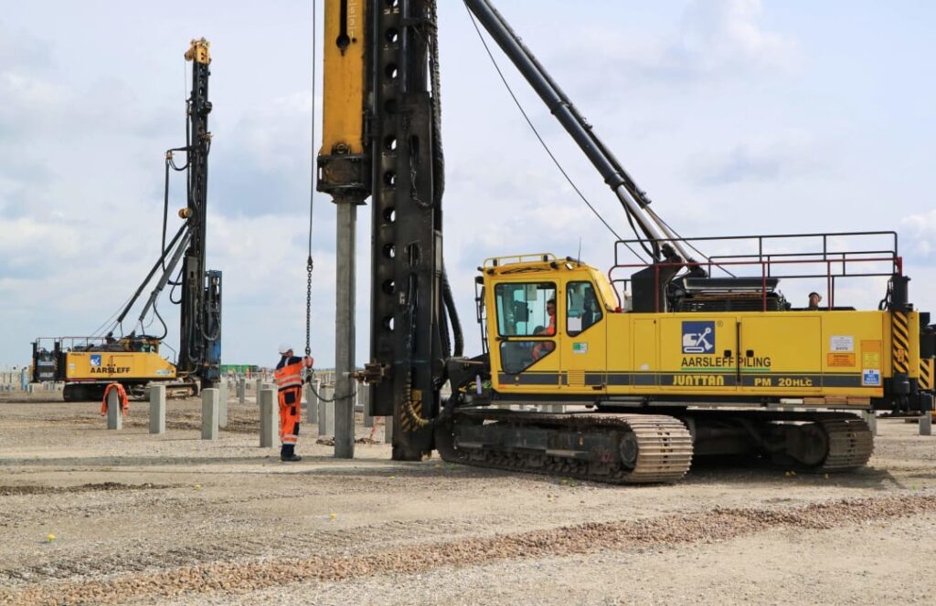
Driven piles are installed by hammering, vibrating, or pressing into the ground. The process displaces soil around the shaft. As the pile enters, it compacts adjacent soil. This increases lateral support and skin friction.
Driven piles gain load capacity from end bearing and shaft resistance. The degree of displacement depends on soil type and pile cross-section. Displacement piles push soil outward, while non-displacement piles allow some soil entry.
Driven piles suit granular soils, where compaction increases capacity. They also offer rapid installation. Engineers use set criteria or driving records to estimate capacity. The process causes noise and vibration. These limit their use near sensitive buildings or equipment.
Engineers monitor blow counts, energy input, and driving resistance. These indicators confirm proper seating and verify soil response. Driven piles do not require excavation or spoil disposal. But refusal may occur if obstructions block full depth.
Bored Piles
Bored piles, also called drilled shafts, are constructed by removing soil and filling the void with concrete. The pile carries load through end bearing, shaft friction, or both. Bored piles do not displace soil during installation.
Engineers use bored piles in urban areas where vibration and noise must remain low. They suit sites with large loads and deep weak layers. Bored piles accommodate large diameters and complex reinforcement.
The process involves excavation, cleaning, and concreting. Support fluids or casings prevent collapse during drilling. Tremie placement ensures concrete flows upward, avoiding segregation or contamination. Reinforcement is inserted before or during concreting.
Quality control is critical. Shaft alignment, cleanliness, and bore stability affect capacity. Engineers verify integrity using sonic or thermal tests. Bored piles often serve heavily loaded structures or deep foundations.
Continuous Flight Auger (CFA) Piles
CFA piles combine drilling and concreting in one operation. An auger drills to depth while soil remains on its flights. As the auger withdraws, concrete is pumped through its hollow stem. Reinforcement is inserted after concrete fills the hole.
CFA piles suit urban sites due to low noise and vibration. They require continuous monitoring of penetration rate, auger withdrawal, and concrete pressure. Loss of control may lead to voids, bulges, or breakage.
These piles perform best in sandy or mixed soils. They struggle in soft clay or collapsing ground. CFA piles allow fast production. However, diameter and depth are limited by machine capacity and reinforcement placement.
Engineers verify integrity with pressure monitoring and volume control. Some projects require low-strain or crosshole tests to confirm concrete continuity. CFA piles balance speed with moderate capacity in suitable soils.
Micropiles
Micropiles are small-diameter bored piles, usually less than 300mm wide. They use high-strength steel elements and pressure-grouted shafts. Micropiles carry load through grout-to-ground bond and steel strength.
They suit restricted sites, retrofit works, and seismic upgrades. Micropiles allow inclined installation and access in low-headroom areas. Their low disturbance and small equipment make them ideal for sensitive foundations.
Micropiles perform well in almost all soils. Engineers drill using rotary or percussion methods. Grouting improves shaft contact and corrosion protection. Grout may be gravity-fed or injected under pressure.
Their capacity comes from bond strength rather than end bearing. Engineers design them to resist tension, compression, or lateral loads. Installation records must track depth, grout volume, and pressure.
Screw Piles
Screw piles, or helical piles, consist of steel shafts with helices. They install by rotation, not impact. As the pile screws into the ground, the helices generate bearing and frictional resistance.
Screw piles suit soft soils, fill areas, or temporary structures. They install quickly and without vibration. Load can be applied immediately after installation. No spoil is produced, and no curing time is needed.
Engineers estimate capacity using installation torque. Torque correlates with soil resistance and shaft friction. The method works best in fine-grained soils. In very dense or hard strata, screw piles may fail to penetrate.
Design accounts for compression, uplift, and lateral loads. Corrosion protection is essential in aggressive soils. Screw piles are useful in remote or sensitive areas. Their speed and simplicity balance limitations in harder ground.
Under-Reamed Piles
A Under-reamed pile has enlarged bases formed by mechanical tools. These base expansions increase bearing area and resist uplift forces. Engineers use them in expansive clays or soft strata where lateral stability matters.
The shaft is bored like a conventional pile. At design depth, a reamer creates the bell or bulb shape. Concrete fills the entire cavity. The enlarged base provides high end-bearing and uplift resistance.
Engineers monitor bore shape, depth, and cleaning. Reinforcement must stay aligned through the bulb. Under-reamed piles reduce settlement by spreading load over a wider area. They also reduce upward movement from swelling soils.
Construction control is critical. Improper reaming or poor cleaning reduces performance. The method suits light to medium structures in reactive clay or fill zones.
Displacement Piles
Displacement piles enter the soil without removing material. Instead, they push soil aside, increasing density and lateral stress. Driven piles, screw piles, and rammed piles often fall into this category.
These types of pile gain capacity from shaft friction and compacted surrounding soil. Displacement minimizes spoil and ground weakening. It improves load transfer and reduces settlement in granular zones.
Installation methods vary. Impact, vibration, or rotation displace soil differently. Engineers assess volume displacement, shaft smoothness, and surface area. Displacement piles work well in sands and fills.
However, they may not suit soft clay or sensitive soils. Lateral pressure can cause ground heave or nearby displacement. Engineers monitor ground response and adjust spacing or sequence to minimize effects.
Non-Displacement Piles
Non-displacement piles remove soil to form a shaft. This includes bored piles, micropiles, and some CFA methods. They generate spoil and create a cavity before filling with concrete or grout.
These piles reduce vibration and suit sensitive environments. They accommodate reinforcement and allow inspection before concreting. Engineers control bore stability with fluids or casings.
A non-displacement pile work well in cohesive soils or variable ground. They require careful cleaning and placement. Soil-softening fluids may reduce shaft resistance if not controlled.
Settlement depends on shaft contact and base cleanliness. Load transfer occurs along the surface and tip. Engineers use testing and inspection to confirm continuity and depth.
Jacked Piles
Jacked piles use static force to push piles into the ground. Hydraulic jacks apply load, usually from superstructure or reaction systems. A jacked pile suits confined spaces or noise-restricted areas.
The process is slow but quiet. Engineers monitor resistance and embedment in real time. Jacked piles often resist compression and tension. Capacity depends on soil displacement and shaft bond.
This method suits underpinning, building retrofits, or sites with poor access. Engineers design the jacking system, sequence, and pile layout. Reaction loads must be verified to prevent uplift or distortion.
Criteria for Selecting the Right Pile Type
Engineers choose pile types based on soil, structure, and site context. Behavior matters more than material or manufacturer. Each pile acts differently. Understanding that difference is the key to good design.
Soil conditions define suitability. Dense sands support driven piles. Soft clays suit bored shafts. Fill or rubble zones need jacked or micro-pile. Soil displacement, friction angle, and water level all influence behaviour.
Structural loading shapes the choice. Heavy axial loads need deep end bearing or strong shaft friction. Lateral loads demand stiffness or group layout. Uplift requires bond strength or enlarged bases.
Site constraints guide installation method. Noise restrictions rule out impact driving. Low headroom limits equipment choice. Slopes, basements, or adjacent structures influence pile location and angle.
Access and logistics also matter. Some sites allow crane access or long rigs. Others require small machines and manual handling. Engineers match pile type to equipment needs.
Durability affects material but also behaviour. Displacement piles compact soils but stress surrounding elements. Non-displacement pile avoid vibration but require spoil disposal. Environmental impact counts.
Speed and cost cannot be ignored. CFA pile offer speed. Driven piles reduce spoil. Bored piles demand more care. Micropiles work in tight spots but cost more. Every choice involves trade-offs.
Testing and validation influence design. A pile may allow dynamic testing. Others require static or sonic checks. Engineers balance confidence, risk, and verification cost.
Regulatory and code requirements add constraints. Seismic zones demand ductility. Flood zones need uplift resistance. Engineers consider codes, standards, and approval processes early in the selection.
Construction sequence also shapes decision. Some piles support early loads. Others require curing or group action. Engineers plan foundations alongside structure and schedule.
No single factor decides the pile type. It’s the intersection of all these criteria that makes the right choice clear.
Conclusion
Pile types differ by behaviour, not just shape or material. Choosing by habit or cost alone can cause failure. Foundation design must cognise how each pile interacts with soil and structure. Selection starts with the ground. It ends with performance. Each pile behaves in a specific way. That behaviour defines its role. Disregarding it leads to excessive settlement, failure, or unnecessary expense.
Every site offers a challenge. Every challenge has a matching solution. But only if the engineer understands what piles really do.
Also See: A Background to Piling
Sources & Citations
- Tomlinson, M.J. and Woodward, J. (2014). Pile Design and Construction Practice (6th ed.). CRC Press.
- Fleming, W.G.K., Weltman, A.J., Randolph, M.F. and Elson, W.K. (2009). Piling Engineering (3rd ed.). Taylor & Francis.
- British Standards Institution. (2015). BS EN 1997-1: Eurocode 7 – Geotechnical Design – Part 1: General Rules. BSI, London.