This article explores the dangers of neglecting initial imperfections in slender columns. It outlines failure mechanisms, relevant design codes, case examples, and best practices for safer engineering.
Structural columns form the backbone of any frame system. They transfer axial loads from beams and slabs to foundations. However, their behavior is not always as straightforward as designers may assume. Particularly in slender columns, initial imperfections—however small—can result in significant instability.
These imperfections are not visible during design. They include minor misalignment, construction tolerances, residual stresses, and eccentric loads. Most engineers assume perfect verticality and centric loading, especially when using structural analysis software. But this assumption is not realistic. Real-world columns are never perfect. A small deviation can grow under load and cause failure earlier than expected.
When designers ignore these initial imperfections, they underestimate second-order effects. Slender columns buckle, amplify internal moments, and displace laterally under load. If not properly checked, the resulting structural failure may appear sudden, but it was long in the making. This article explores the dangers of neglecting initial imperfections in slender columns. It outlines failure mechanisms, relevant design codes, case examples, and best practices for safer engineering.
Initial Imperfections in Structural Columns
Every built column contains some imperfection. Columns may be slightly crooked due to poor formwork or misalignment. They may be eccentrically loaded because beams and slabs shift the center of gravity. Reinforcement may be off-center due to congestion or poor fixing. Even differential settlement from the foundation can introduce unintended eccentricity.
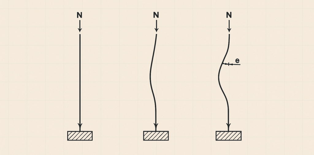
These imperfections exist even before loading. They are initial in the sense that they are not caused by the applied load but exist independently. While minor in geometry, their effect on structural performance is significant. In slender columns, even small eccentricities generate bending. These secondary moments increase as the column deflects under load—a phenomenon called the P-Delta effect.
The Eurocode and other design codes recognize this. They include factors and methods to account for these imperfections. But in practice, engineers often skip the checks or rely entirely on software defaults. This approach might simplify analysis but hides danger.
The Slenderness Ratio and Column Stability
Slenderness ratio quantifies the column’s tendency to buckle. It is the ratio of effective height to radius of gyration:
\lambda=\frac{l_{leff}}{i}Where:
- leff = effective length of the column
- i= the radius of gyration
Higher values of λ indicate slender behavior. For slender columns, axial compression alone does not determine capacity. Lateral deflection introduces bending moments. This interaction between axial and lateral forces must be included in design.
The Eurocode 2 classifies columns as slender if their slenderness exceeds a critical value:
λ>λlim
Where λlim depends on the type of support and axial load level. If a column is slender, engineers must consider second-order effects.
The P-Delta Effect and Amplified Moments
The P-Delta effect arises when an axial load P acts on a column that is laterally displaced by Δ (See: Assessing the Stability of Frames | Second Order Effects). This creates a moment M=P⋅ΔM, which increases deflection and further amplifies the moment.
In slender columns, this feedback loop is dangerous. It leads to non-linear behavior and may cause buckling even at loads below the material strength limit. The Eurocode 2 provides a simplified method using moment magnification:
M_{Ed}=M_{Ed,1}\times \deltaWhere:
- M1,Ed= first-order moment due to applied load
- δ = amplification factor
The value of δ depends on slenderness, eccentricity, and load level. Designers must compute it to account for imperfection effects.
Common Engineering Assumptions That Fail
Many engineers assume that a vertical column with axial loading will remain vertical. They input centerline loads in software, define fixed supports, and trust the output. Unfortunately, this assumption misses critical real-world details.
Columns are rarely loaded at the exact centroid. Beams transfer loads eccentrically, columns may lean due to construction tolerances, and loads may shift during use. If these are not reflected in the model, the design is invalid.
Furthermore, software tools often ignore second-order effects unless explicitly requested. Linear analysis assumes geometry does not change under load. But in slender columns, geometry does change—lateral displacement alters internal forces. Without non-linear or amplified analysis, the model underestimates bending moments.
This false simplicity can have serious consequences, especially in multistory structures or high-rise frames. One overlooked eccentricity may compromise an entire floor system.
A Real-World Example: The Hyderabad Office Tower Collapse
In 2016, a reinforced concrete office tower in Hyderabad, India, collapsed during construction. Investigations revealed that columns on the fourth and fifth floors buckled. They were slender and under heavy load from upper floors.
Site inspections later revealed slight leanings and construction tolerances that introduced initial imperfections. Under increasing load, lateral deflection magnified. The columns could not resist the combined axial and bending forces.
The collapse killed 11 workers. The project was abandoned. And yet, the structural error was subtle: not a lack of strength, but a failure to account for column instability.
Design Code Provisions and Safety Margins
Eurocode 2 (EN 1992-1-1) provides comprehensive guidelines for slender column design. Clause 5.8 covers second-order effects. It outlines two methods:
- General Method: Requires a non-linear analysis with updated geometry (second-order). Suitable for irregular frames.
- Simplified Method: Uses moment magnification and stability criteria. Applicable to isolated columns.
The code defines a design imperfection as:
e_0=\frac{l_0}{400}Where l0 is the column’s height. This imperfection is treated as an initial eccentricity. It must be added to any applied eccentricity to compute total moment:
M_{Ed}=N_{Ed}\cdot(e_{applied}+e_0)The code also allows designers to use nominal curvature methods. These provide quick estimates of second-order effects based on stiffness and load duration.
Despite these tools, many engineers skip these checks—either out of habit, ignorance, or overreliance on software.
How Construction Practices Introduce Imperfections
Imperfections in slender columns are not only theoretical. They arise naturally on site.
- Formwork displacement: Verticality often deviates by 5 to 15 mm per floor
- Bar misplacement: Reinforcement cages may be off-center, reducing moment resistance
- Footing tilt: Foundation settlement shifts column bases out of alignment
- Beam offset: Connection details may introduce unintended eccentric loading
Engineers must assume these occur. Even with the best supervision, construction tolerances make perfect columns impossible.
These minor deviations are manageable only when accounted for in design. Ignoring them leaves no margin for real-world behavior.
Recommendations for Safer Design Practice
- Model Imperfections Deliberately: Always include geometric imperfections. Add eccentricity and sway in analysis models. Do not trust centerline geometry alone.
- Check Column Slenderness Early: Use preliminary sizing to identify potential slender columns. Design with second-order effects in mind.
- Use Eurocode Amplification Factors: Follow EN 1992-1-1 guidelines. Calculate δ\delta and apply it to moments. Include design eccentricity.
- Review Construction Tolerances: Discuss tolerances with site engineers. Account for practical deviations in verticality and alignment.
- Avoid Oversimplified Software Models: Confirm whether the analysis tool includes second-order effects. If not, apply manual amplification.
- Monitor Columns During Construction: Install verticality sensors or use plumb lines. Detect deflections early before they compound.
Conclusion
Simplification makes analysis easier. But when simplification replaces judgment, failures occur. The real world does not follow textbook assumptions. Columns are never perfectly straight or loaded at their center. Initial imperfections are inevitable. They may be invisible, but their effects are not. Engineers who ignore them expose structures to unpredictable behavior.
Also See: Design a Slender Concrete Column to Eurocode 2
Sources & Citations
- EN 1992-1-1: Eurocode 2 – Design of Concrete Structures. European Committee for Standardization (CEN), 2004.
- Allen, E., & Iano, J. (2017). Fundamentals of Building Construction. Wiley.
- MacGregor, J. G., & Wight, J. K. (2012). Reinforced Concrete: Mechanics and Design. Pearson.