The article explains influence lines in structural analysis, their applications, and how they help engineers determine critical load positions for maximum internal forces. It includes a detailed worked example for a bridge beam.

Structural engineers analyze how loads affect structures using various tools. Influence lines help in understanding how loads move across a structure. They show how a unit load affects internal forces and reactions at different positions. Engineers use influence lines to design bridges, beams, and other structures carrying moving loads.
Influence lines differ from bending moment and shear force diagrams. These diagrams show the effects of fixed loads, while influence lines consider moving loads. Engineers use influence lines to determine maximum effects from loads like vehicles on bridges. They help optimize design by predicting worst-case loading conditions.
The importance of influence lines extends beyond bridges. They apply to any structure where load positions vary. Understanding their use ensures safe and efficient designs. Engineers apply influence lines in various structures, including floors, crane beams, and conveyor supports. They provide a simple yet powerful tool for analyzing structural behavior under dynamic conditions.
Basic Concept of Influence Lines
An influence line shows how a reaction, shear force, or moment changes as a unit load moves along a structure. Engineers develop these lines by applying a unit load at different positions. The resulting function helps determine maximum and minimum values for a given structural effect.
Influence lines apply primarily to statically determinate and indeterminate structures. In determinate structures, influence lines consist of straight segments. In indeterminate structures, they appear as curves due to load redistribution. Engineers often use numerical methods to analyze influence lines in complex structures.
Influence lines help in designing structures that experience moving loads. Bridges, crane beams, and rolling loads on platforms require influence line analysis. By understanding how forces change with movement, engineers can determine the worst-case loading scenario.
Difference Between Influence Lines and Shear/Moment Diagrams
Shear force and bending moment diagrams display internal forces from fixed loads. They help engineers design for permanent loading conditions. Influence lines, however, show the effect of a single moving load. They determine the most critical position of the load for maximum response.
For example, a bridge beam supports vehicles moving in different positions. Influence lines help identify the location of the highest bending moment or shear force. Engineers place reinforcement accordingly to resist these peak values. This approach ensures material efficiency and structural safety.
A major distinction between shear/moment diagrams and influence lines is that the former applies to fixed loads, while the latter applies to moving loads. This distinction makes influence lines crucial in transportation infrastructure, where moving loads dictate design considerations.
Applications of Influence Lines
Influence lines have various applications in structural engineering. They are essential in designing bridges, floor systems, and conveyor structures. Engineers use them to analyze:
- Bridge Design – Influence lines determine maximum bending moments and shear forces due to moving vehicles.
- Crane Runways – Moving loads from cranes generate varying forces on supporting beams. Engineers optimize support placements using influence lines.
- Multi-Storey Structures – Floors carrying moving loads, like trolleys or forklifts, benefit from influence line analysis.
- Elevated Rail Tracks – Tracks carrying trains require influence line analysis to optimize beam strength and reinforcement.
- Temporary Structures – Scaffolding and movable platforms experience shifting loads, requiring influence lines for stability.
Influence lines also apply in the analysis of industrial structures. Conveyor systems, loading docks, and gantry cranes rely on influence lines for efficient load distribution.
Construction of Influence Lines
Engineers construct influence lines using two main methods:
- Static Equilibrium Method – Suitable for statically determinate structures. Engineers shift a unit load along the structure and analyze reactions.
- Müller-Breslau Principle – Useful for both determinate and indeterminate structures. Engineers replace the function of interest (reaction, moment, or shear) with a kinematic displacement. The resulting deflected shape represents the influence line.
The Müller-Breslau principle is particularly useful in complex structures. It allows engineers to visualize how forces redistribute when loads move across a structure.
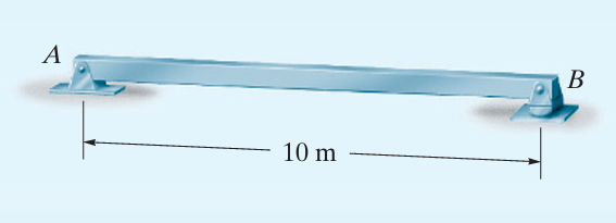
Worked Example: Influence Line for a Bridge Beam
A simply supported bridge beam has a span of 10 meters. A truck moves along the beam, causing varying reactions and internal forces. Determine:
- The influence line for the reaction at support A.
- The influence line for the shear force at a section 4 meters from A.
- The influence line for the bending moment at the midspan.
Step 1: Influence Line for Reaction at A
Consider a unit load moving along the beam. Let x be the distance of the load from A. By taking moments of support B:
R_A= \frac{10-x}{10}For different positions of the unit load:
- When the load is at A (x=0) RA=1
- When the load is at B (x=10); RA=0.
The influence line is a straight line from 1 at A to 0 at B
Step 2: Influence Line for Shear Force at 4m from A
The shear force at 4m depends on the load’s position. Consider two cases:
Load just left of section (at x<4)
R_A= \frac{12-x}{12}Shear at 4m:
V=R_A
When the load is just at the right of section i.e (x>4m)
V=R_A-1
Solving for both cases:
When x=4, just left:
V=\frac{12-4}{12} =\frac{2}{3}When x=4, just right:
V=\frac{12-4}{12}-1 =\frac{2}{3}-1=-\frac{1}{3}The influence line has a jump at 4m. The left segment has a positive value, and the right segment has a negative value.
Step 3: Influence Line for Bending Moment at Midspan
The bending moment at the midpoint is given by:
M_A=R_A\times 5
Substituting for RA
M_A=(\frac{10-x}{10})\cdot 6 =3(\frac{10-x}{5})For key positions:
- When x=0; M=6
- When x=10: M=0
- When x=5(midspan): M=3
The influence line forms a triangular shape, peaking at the midspan.
Conclusion
Influence lines are crucial in structural engineering. They help determine the critical locations of loads for maximum internal forces. By analyzing influence lines, engineers ensure structures can safely resist moving loads.
This worked example demonstrates their application in bridge design. Influence lines provide insights into the best load placements for safety and efficiency. Engineers apply them in bridge analysis, industrial structures, and floor systems to ensure optimal performance.
Also See: Displacement of Trusses | Principles of Virtual Work
Sources & Citations
- Hibbeler, R. C. (2017). Structural Analysis (10th ed.). Pearson Education.
- Kassimali, A. (2015). Structural Analysis (5th ed.). Cengage Learning.
- McCormac, J. C., & Nelson, J. K. (2018). Structural Analysis: Engineering Concepts and Applications. Wiley.