This article explores the essential components like general arrangement drawings and connection details, required to read and interpret structural steel-work drawings with confidence.
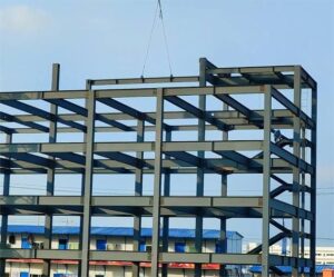
Structural steelwork drawings are critical for engineers, fabricators, and builders. They offer detailed information about the layout, dimensions, and connections of steel-framed structures. These drawings ensure clear communication between the design team and those who bring the structure to life. However, the symbols and terminology can be daunting to the untrained eye.
Understanding structural steelwork drawings requires knowledge of industry-specific conventions and protocols. Fabricators rely on these drawings to construct the components of the steel framework. Engineers use them to confirm that the design intent is fulfilled during construction.
Thus, this article explores the essential components like general arrangement drawings and connection details, required to read and interpret structural steel-work drawings with confidence.
Structural Steelwork Drawings
Steel drawings are mostly not fragmented as in concrete structures, in most instances almost all the details can be shown on the GA, with the exception of connections which are shown on different drawings. Steel structural drawings are usually more diagrammatic than concrete structural drawing. In fact, it is advised, that when producing steel drawings, a diagrammatic style should be employed. In preparing their G.A all beams and trusses are drawn as single line. The labelling of the structural elements should adopt a South -North/Down to Up and East to West/Right to Left method.
Structural steelwork drawings are divided into two main categories: Design General Arrangement Drawings and Fabrication General Arrangement Drawings.
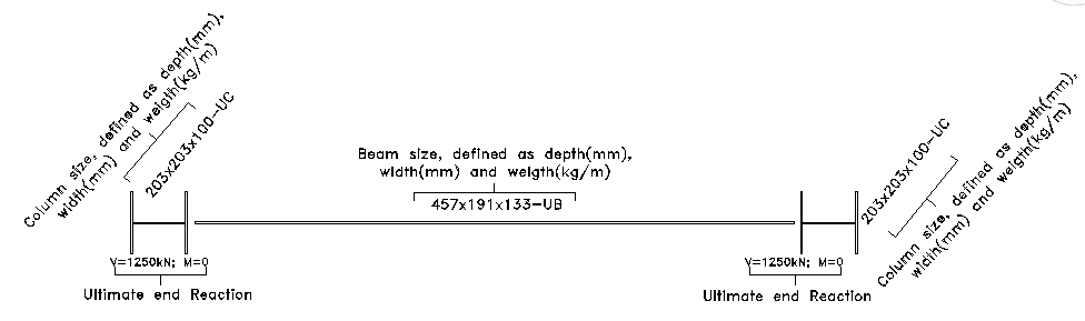
Design General Arrangement Drawings present a simplified diagram of the structure’s layout. Beams and columns are represented by thick lines, while bracing uses dashed lines. These drawings are to scale and provide essential information like dimensions and layout relationships. For example, in Figure 1, beams and their reactions are represented as thick lines showing how they connect to other elements.
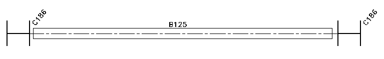
The general arrangement developed by the design engineer shows all structural elements on a single plan as shown above. However, the one developed by the steel fabricator, shows only the steelwork elements of the structure. The steel beams are drawn to scale in plan and rather than label the size of the elements in the frame, the fabricator instead give them a unique marker. These markers are used to designate the structural elements, which the steel fabricator refers to when constructing the steel frame The elements in these drawings correspond to the overall design but include additional details essential for the construction phase, as seen in Figure 2.
Both sets of drawings work together to ensure the design’s successful translation into physical structures. While the design general arrangement focuses on the larger picture, the fabrication drawings zoom in on specifics.
Key Components in Steelwork Drawings
Beams and Columns
Beams and columns are the primary components of any steel-framed structure. They are responsible for supporting loads and transferring forces.
Labelling System: Structural steel elements are labelled according to standardized dimensions. For example, “203x203x86 UC” refers to a universal column that is 203 mm deep and 203 mm wide, with a weight of 86 kg per meter. It is important to note that these are serial sizes, not actual dimensions. The actual depth may vary depending on the weight per meter.
Hollow and Angle Sections: Angle sections (RSA) and hollow sections (RHS) are also commonly used. Their labels are more straightforward. For example, “150x100x5 RHS” means a rectangular hollow section that is 150 mm deep, 100 mm wide, and has a 5 mm thickness. Similarly, “120x120x12 RSA” indicates an angle section with specific width and thickness.
Labelling in steelwork drawings helps simplify communication. By using standard notation, engineers can quickly communicate material requirements to fabricators.
Connection Details
Connections between beams, columns, and bracing ensure that loads are distributed properly within the structure. Accurate interpretation of connection details is essential for both engineers and fabricators.
Connections can be bolted, welded, or pinned, depending on the structural requirements. Bolted connections are common for beams joining columns, while welded joints are used where more rigidity is needed. General arrangement drawings does not provide basic details about these connections, but includes the forces they will handle (shear, axial loads, etc.), as seen in Figure 1.
Design drawings focus on the structural intent of connections, not the specifics. They show forces and constraints but do not indicate exact bolt sizes or weld types. These specifics are determined by the fabricator based on the design engineer’s guidelines.
Fabrication drawings, show exact connection details. These drawings provide information about bolt sizes, weld lengths, and stiffeners needed to maintain structural integrity. The fabricator uses these drawings to construct steel components according to the design specifications.
Understanding how connections are represented in both general and fabrication drawings ensures the correct assembly of the steel structure.
Symbols and Notation in Steelwork Drawings
Structural steelwork drawings rely on standardized symbols to convey essential information. These symbols ensure consistency across projects.
Welding Symbols: Welding symbols are defined in BS EN 22553:1995. They include information about the type, size, and location of welds (See: Design of Welded Connections). For instance, a fillet weld is represented by a triangular symbol, with additional details about the weld’s throat thickness and length.
Elevation Indicators: Common symbols used to represent levels in steelwork include TOS (Top of Steel), SSL (Structural Slab Level), and FFL (Finished Floor Level). TOS indicates the elevation at the top surface of a steel element, while SSL and FFL help coordinate the steel frame with other building systems, such as flooring.
Familiarity with these symbols ensures clarity and reduces the risk of errors in the design and fabrication processes.
For more on drawing notations see: Structural Drawings Connotations and Interpretation
Fabrication Drawings and Shop Drawings
Once the design general arrangement drawings are completed, fabricators take over to create the steel components. Fabrication drawings offer more specific instructions for each part of the structure.
Fabrication General Arrangement Drawings
Fabrication drawings, like those shown in Figure 2, are based on the design general arrangement. They focus on the steel elements required for construction. These drawings include all necessary details for cutting, welding, and assembling the steel. Each element in the drawing is labelled with a unique marker corresponding to a table of member sizes.
Fabrication drawings often indicate where bolt holes should be drilled, how welding should be performed, and where stiffeners should be placed. These instructions are essential for fabricating components that will fit together correctly on-site.
Shop Drawings
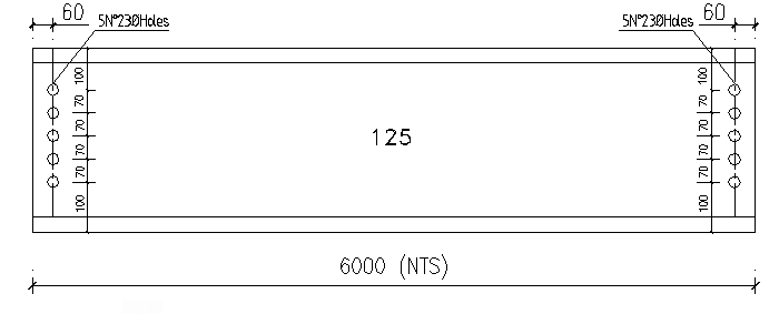
Shop drawings are even more detailed than fabrication drawings. They show each individual component, including precise dimensions and connection details. Figure 3 illustrates a beam drawn as a fabrication element with specific features like bolt holes and weld placements. These drawings ensure that all components are manufactured to the exact specifications needed for assembly.
Shop drawings ensure that each part of the steel frame is built correctly. These drawings are often used as references during the actual construction process.
Using CAD and 3D Models for Structural Steelwork
Computer-Aided Design (CAD) has revolutionized the field of structural steelwork. 3D models are now commonly used to visualize structures and solve potential issues before construction begins.
3D Models
CAD software enables engineers to create 3D models of steel structures. These models allow users to zoom in on details, view components from different angles, and check for potential clashes between elements. While 3D models provide an overall view, the same labelling conventions used in 2D drawings apply.
Enhanced Visualization
Viewing a 3D model can reveal problems that might not be obvious in 2D drawings. Engineers and contractors can identify any issues early and resolve them before construction, saving time and reducing costly errors.
Despite the advent of 3D modelling, understanding traditional 2D drawing conventions remains essential.
Conclusion
Reading and interpreting structural steelwork drawings is essential for anyone involved in designing, fabricating, or constructing steel structures. An understanding of general arrangement drawings, connection details, and the symbols used in steelwork drawings allows professionals to ensure that designs are translated accurately into physical buildings.
Also See: How to Interpret Reinforced Concrete Drawings
Sources & Citations
- The Institution of Structural Engineers (2006) Standard Method of Detailing Structural Concrete. 3rd ed. London: The Institution of Structural Engineers
- The Institution of Structural Engineers (2012) Reading Structural Steelwork Drawings. Technical Guidance Notes 13(1).