This article lays out the way in which reinforced concrete drawings should be read. In many cases reinforced concrete drawings are more diagrammatic than their general arrangement counterparts and carry with them their own unique set of rules and nomenclature.
Reinforced concrete drawings in the construction process, provides detailed guidance on how to lay out and place reinforcing bars within concrete structures. These drawings often have their own set of rules and symbols that differ from general arrangement drawings. For those involved in the construction process—whether engineers, contractors, or site workers—understanding these drawings is critical to ensuring that the reinforcement is installed correctly. The accuracy and clarity with which these drawings are interpreted will directly affect the strength and durability of the final structure.
The purpose of reinforced concrete drawings is to communicate the layout of reinforcing bars to installers. These drawings serve as instructions for where and how bars should be placed within various concrete elements. Unlike general arrangement drawings, which may include overall dimensions and layouts of a structure, reinforced concrete drawings focus on the internal reinforcement details. The drawings often use specific notations, such as bar marks, which are linked to bar bending schedules that provide more detailed information about the dimensions and shape of each reinforcing bar.
Reading reinforced concrete drawings can initially seem daunting due to the complexity and specific terminology they contain. However, with a clear understanding of the key principles and nomenclature, these diagrams become easier to follow. This article will provide a comprehensive guide on how to interpret reinforced concrete drawings, focusing on the drawing principles, key terminologies, and how they are applied in practice. It will also touch on common elements like columns, beams, slabs, and walls, as well as the bar bending schedules that often accompany these drawings.
Drawing Principles
As mentioned, reinforced concrete drawings communicate the arrangement and placement of steel bars within concrete elements such as beams, columns, and slabs. They differ from general arrangement drawings, as they focus exclusively on reinforcement and omit many other construction details. The primary objective of these drawings is to ensure that the installer understands where to place the reinforcement bars and how to configure them to maximize the structural integrity of the element.
One key aspect of reinforced concrete drawings is that they are not always drawn to scale, especially in cases where they are more diagrammatic than spatially accurate. The dimensions provided on the drawings often relate only to the placement of reinforcement that cannot be fixed to an obvious reference point. However, in the age of CAD (Computer-Aided Design), this limitation has become less common. Many modern reinforced concrete drawings are to scale, making them easier to read. When certain elements, like beams or slabs, have repeated patterns, a tabulated approach may be used to present the information. This minimizes the amount of drawing required for repeating elements.
It is also important to note that reinforced concrete drawings should always be read in conjunction with general arrangement drawings. The latter provides the essential setting-out dimensions for the concrete elements themselves, without which the reinforcement drawing would lack context. The two types of drawings are complementary, and both must be referenced to ensure the correct placement of concrete elements and reinforcement.
Drawing Connotations
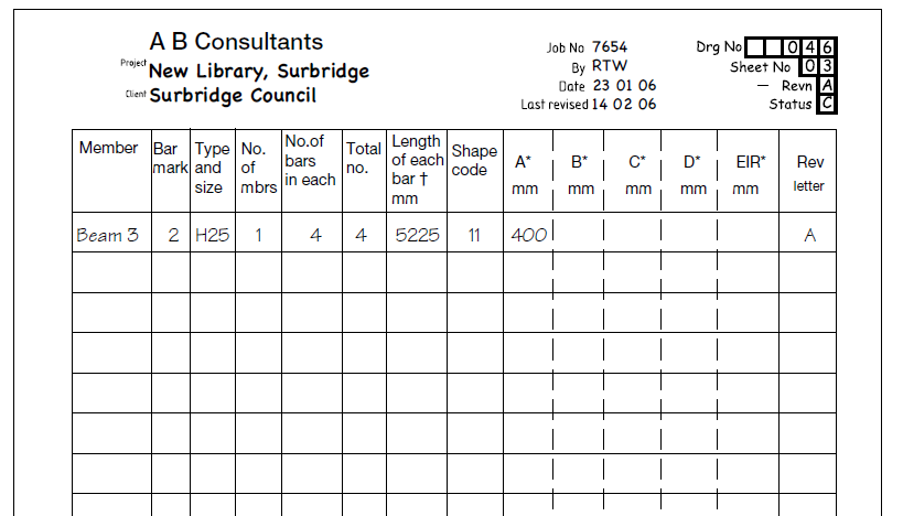
The key to interpreting reinforced concrete drawings lies in understanding the specific terminology used to describe the reinforcing bars. Every reinforcing bar (Figure 1) in a drawing is assigned a unique identifier known as a “bar mark.” This bar mark is linked to a document called a bar bending schedule (Figure 2), which provides more detailed information about the bar’s size, shape, and quantity. The bar bending schedule allows for easy reference between the drawing and the specific bars being used in the project.
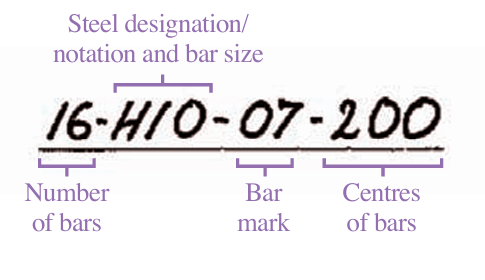
The label associated with each bar mark in the drawing includes various details about the bar, such as its size, grade, frequency, and elevation within the concrete element (see Figure 1). For example, the steel grade of the reinforcement is indicated by a letter, typically “H” for standard reinforcing bars. Other grades of reinforcement, such as A, B, and C, indicate bars with varying levels of ductility, with Grade C being the most ductile. Grade A bars, for example, are cold-formed and are commonly used in shear-links, but they are limited in diameter to a maximum of 12 mm.
The concept of bar marks is crucial when reading reinforced concrete drawings. Each bar has a unique number, and this number is linked to the bar bending schedule, which provides detailed information about its dimensions. This system of bar marks and schedules ensures that the reinforcement is installed as intended and facilitates easy identification of each bar during the construction process.
Beams and Column Reinforcement Drawings
Different structural elements require different types of reinforcement, and the drawings for beams, columns, and slabs reflect this.
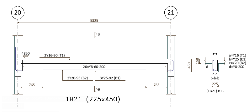
Beam reinforcement drawings are typically the simplest to interpret. They provide much of the information in a diagrammatic form and do not require unique terminologies beyond the standard bar marks. The key element to pay attention to in beam reinforcement drawings is the extent of the bars and how they overlap or “lap” with each other. Lapping is critical for maintaining the continuity of the reinforcement within the beam. Figure 3 is an example of an annotated reinforced concrete beam detail.
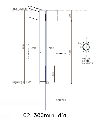
Column reinforcement drawings tend to be more diagrammatic than beam drawings. They typically show the primary reinforcement bars, as well as dashed lines to indicate the extent of starter bars. Starter bars project from previously cast concrete and maintain continuity between old and new concrete. A section is often taken through the column to indicate how the bars are laid out, helping the installer understand the reinforcement’s placement throughout the column’s height. See Figure 4 for example of reinforced concrete column drawing.
Slab Reinforcement Drawings
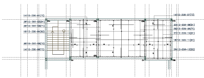
Slab reinforcement drawings can be among the most complex, particularly in flat slabs where multiple layers of reinforcement are required. Floor slabs often have at least four layers of reinforcement: two for the top layer and two for the bottom. These layers must be carefully plotted to avoid overcrowding the drawing, and it’s common to create separate drawings for the top and bottom layers of reinforcement.
Critical to the clarity of interpreting reinforced concrete slab drawings is the use of extent indicators. Extent indicators help in showing the area that a bar occupies and the centers where they are placed, thus, making the drawings more readable. Figure 5 shows an example of a reinforced concrete drawing of slab.
Wall Reinforcement Drawings
Walls, like columns, often include starter bars that project from previously cast sections of concrete. Wall reinforcement drawings share similarities with slab drawings in that they use a unique marker to indicate the location of each reinforcing bar within the wall.
In some cases, wall reinforcement drawings may use nomenclature such as N1, N2, F1, or F2 to specify the placement of bars at different levels within the wall. The bars must be set out in relation to the kicker, which is a section of concrete cast above the structural slab level. Other than the presence of the kicker, the process of reading wall reinforcement drawings is similar to that of slab drawings.
Bar Bending Schedule
Finally, no reinforced concrete drawing is incomplete without a bar bending schedule. This document provides detailed information about the size, shape, and length of each reinforcing bar used in the project. It is essential for ensuring that the bars are bent and cut to the correct dimensions before being placed within the concrete. The bar bending schedule uses standard shape codes, such as U-bars or L-bars, as defined in national standards like BS 8666.
The bar bending schedule is structured in a table format and includes several columns of information. These typically include the bar mark (unique identifier), the type and size of the bar, the number of members that the bar is located within, the total number of bars, and the length of each bar. The shape code column specifies the bending configuration of the bar, while other columns provide detailed dimensions for bent sections of the bars. When interpreting a reinforced concrete drawing, it is crucial to cross-reference the bar marks in the drawing with the corresponding information in the bar bending schedule.
Practical Application and Best Practices
Understanding reinforced concrete drawings is crucial for successful construction projects. To ensure accuracy in interpretation, it is essential to follow these best practices:
Always cross-reference with general arrangement drawings: Reinforced concrete drawings only provide information about the reinforcement. The concrete elements themselves are detailed in general arrangement drawings, which provide the overall dimensions and layout.
Use the bar bending schedule: The bar marks in the drawing are incomplete without the bar bending schedule. Always refer to the schedule to ensure that the bars are bent and cut to the correct dimensions.
Pay attention to lap lengths and curtailment: Lapping ensures the continuity of reinforcement within the structure, and curtailment refers to the length and location of the bars. These factors are critical for maintaining the structural integrity of elements like beams and slabs.
Understand the Connotations: Familiarize yourself with the specific terms used in reinforced concrete drawings, such as bar marks, kickers, and starter bars. Knowing these terms will help you interpret the drawings more effectively.
Check for tolerances and concrete cover: Reinforcement must be placed with the correct cover to ensure durability. National standards provide guidance on the allowable tolerances for bar placement and concrete cover.
Also See: Preparation and Interpretation of Bar Schedules
Conclusion
Interpreting reinforced concrete drawings is a skill that requires attention to detail and an understanding of the unique connotations used in the drawings. Following the principles outlined in this article, ensures that reinforcement is installed correctly, contributing to the strength and durability of the final structure. Always remember to cross-reference reinforced concrete drawings with general arrangement drawings, use the bar bending schedule for detailed information, and follow best practices for interpreting the layout and placement of reinforcing bars.
Sources & Citations
- The Institution of Structural Engineers (2012). Reading Reinforced Concrete Drawings. The Structural Engineer, August 2012, pp. 29-31.
- The Institution of Structural Engineers (2006). Standard Method of Detailing Structural Concrete, 3rd ed. London: The Institution of Structural Engineers.