This article explores suspension bridges, their components, analysis, and design. It details the procedures used to analyse, design, and construct them.

Suspension bridges are among the most remarkable achievements in civil engineering. They span great distances with elegance and efficiency, using cables to carry loads across vast obstacles. Their design relies on principles of tension and compression, allowing for lightweight structures capable of spanning kilometers. Engineers favor them for their ability to cross wide rivers, deep valleys, and busy urban centers without extensive support structures.
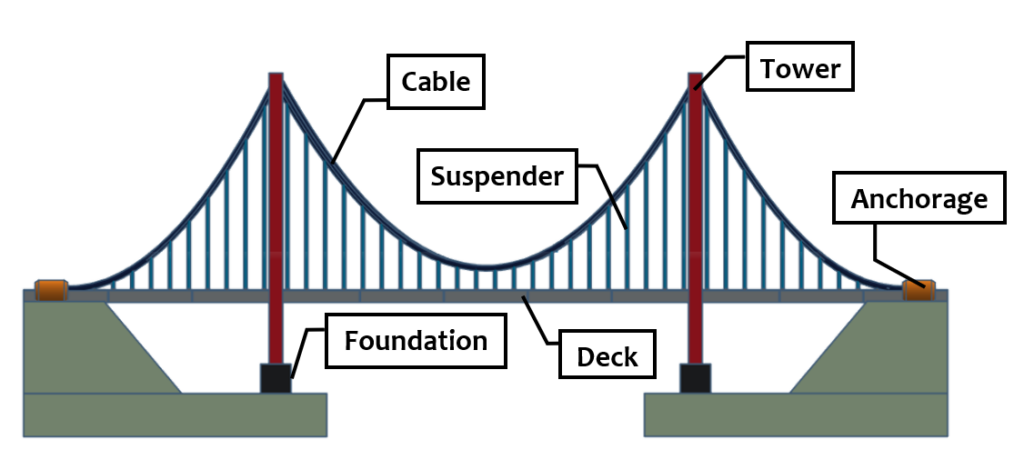
These bridges stand apart due to their unique structural behavior. Unlike beam or arch bridges, suspension bridges use cables as primary load-bearing elements. The deck hangs from vertical suspender cables attached to massive main cables (Figure 1). These main cables stretch over tall towers and anchor firmly into the ground. This system efficiently transfers forces, ensuring stability and durability.
The engineering behind suspension bridges has evolved over centuries. Early versions used vines and ropes, while modern designs use high-strength steel cables and advanced materials. Innovations in analysis and construction techniques have allowed longer spans and stronger structures. This article explores their history, components, analysis, and design. It details the procedures used to develop and construct them
History of Suspension Bridges
Suspension bridges have existed for thousands of years. Ancient civilizations built rudimentary versions using natural materials. The Inca Empire in South America constructed rope bridges using woven grass. These early structures demonstrated the basic principle of using tension to support loads. However, they lacked durability and could only span short distances.
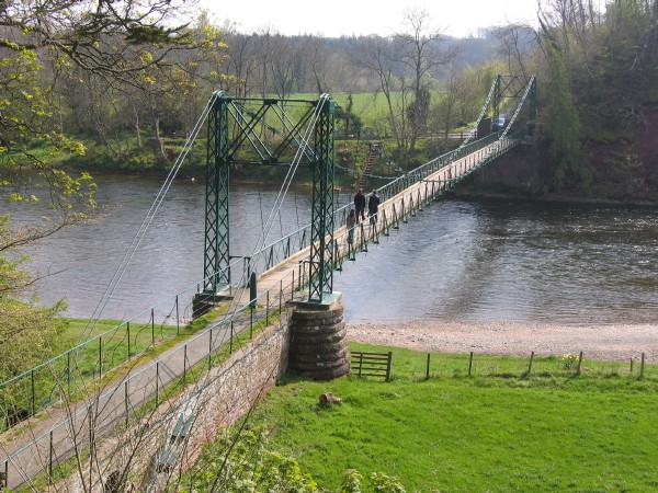
The concept advanced significantly in the late 18th and early 19th centuries. Engineers began using iron chains instead of ropes, creating stronger and more durable structures. The first iron-chain suspension bridge, the Dryburgh Abbey Bridge in Scotland (Figure 2), opened in 1817. It demonstrated the advantages of metal over organic materials. Soon, engineers replaced iron chains with wrought iron and later steel cables.
Modern suspension bridges differ from other bridge types in their load distribution. Beam bridges rely on bending resistance, while arch bridges depend on compression. In contrast, suspension bridges transfer most loads through tension in the cables. This allows for longer spans and reduced material usage. The longest suspension bridges in the world exceed 2,000 meters in span, a feat impossible with other bridge types.
Key Components of a Suspension Bridge
Suspension bridges consist of several essential components that work together to maintain stability and strength. Each part plays a crucial role in carrying loads and ensuring durability.
Main Cables
The main cables are the most critical load-bearing elements. They stretch between anchorages, passing over the bridge towers. These cables support the entire deck through vertical suspender cables. They experience pure tension and distribute loads efficiently to the anchorages.
Towers
Towers provide vertical support for the main cables. They transfer loads to the foundation and withstand significant compression forces. Their height determines the sag of the main cables, influencing structural efficiency. Engineers design them to resist lateral and vertical forces.
Anchorages
Anchorages secure the main cables at both ends of the bridge. They prevent the cables from pulling free under tension. These structures must resist massive horizontal forces. Engineers embed them deep into bedrock or massive concrete blocks to ensure stability.
Suspender Cables
Suspender cables connect the deck to the main cables. They transfer the deck’s weight to the main cables, which then carry the loads to the towers and anchorages. They experience pure tension and are evenly spaced along the deck.
Deck
The deck is the roadway of the bridge. It carries vehicular and pedestrian traffic. Engineers design it to be lightweight yet strong enough to handle loads. It must also resist wind forces and vibrations. The deck’s stiffness influences the overall stability of the bridge.
Wind Bracing Systems
Wind bracing ensures the bridge remains stable under wind loads. Early suspension bridges suffered from aerodynamic instability, leading to catastrophic failures. Modern designs incorporate stiffening trusses or aerodynamic box girders to reduce oscillations.
Structural Analysis of Suspension Bridges
Structural analysis ensures the bridge remains stable and safe under all expected loads. Engineers use mathematical models and software tools to evaluate forces and deformations.
Load Distribution
Suspension bridges distribute loads primarily through tension in the cables. The deck transfers its weight to the suspender cables, which pull on the main cables. These main cables carry the load to the towers and anchorages. The towers experience compression, while the anchorages resist horizontal pull.
Equation of the Cable Curve
The main cables form a catenary shape under their own weight. However, under uniform deck loading, they approximate a parabolic curve. The equation governing cable shape under uniform loading is:
y=\frac{wx^2}{2T}Where: y is the cable deflection, w is the uniform load, x is the horizontal distance, and T is the horizontal cable tension. Engineers use this equation to determine cable forces and design parameters.
Deck and Stiffening Systems
The deck must remain stable under live loads, wind, and temperature changes. Engineers use stiffening trusses or box girders to enhance rigidity. These elements prevent excessive bending and vibration. The analysis considers bending moments, shear forces, and dynamic effects.
Wind and Aerodynamic Stability
Suspension bridges are highly sensitive to wind forces. Engineers analyze aerodynamic effects to prevent instability. The famous Tacoma Narrows Bridge collapse in 1940 highlighted the dangers of wind-induced oscillations. Modern designs use wind tunnel testing and computational fluid dynamics to improve stability.
Design of Suspension Bridge Components
Designing a suspension bridge involves careful calculations to ensure safety and efficiency. Engineers follow a step-by-step approach to design each component.
Design of Main Cables
The main cables must withstand tension forces while minimizing weight. Engineers determine cable diameter based on the total bridge load and allowable stress. The equation for cable tension is:
T=\frac{wL^2}{8d}where T is the tension, w is the uniform load, L is the span length, and d is the sag depth.
High-strength steel wires are bundled to form large cables. Engineers select wire diameters and the number of strands to achieve the required strength. The cables are coated to prevent corrosion and increase durability.
Design of Towers
Towers must support the main cables and resist compression forces. Engineers design them as reinforced concrete or steel structures. The height depends on the desired cable sag, which affects load distribution. Stability considerations include buckling resistance and lateral wind forces.
Design of Anchorages
Anchorages must resist the massive horizontal pull of the cables. Engineers embed them deep into rock or construct large concrete blocks. The design ensures sufficient resistance to prevent displacement.
Design of Deck and Suspender Cables
The deck must carry traffic loads while remaining lightweight. Engineers design it as a steel or reinforced concrete structure. It must withstand bending moments, shear forces, and vibrations. Suspender cables are sized based on tension requirements.
Construction of Suspension Bridges
The construction of a suspension bridge follows a systematic process. Engineers first build the towers and anchorages. They then string temporary cables to guide the installation of the main cables. Workers pull the main cables into place and secure them. Suspender cables are attached, and the deck sections are lifted and installed. Finally, engineers conduct load tests to verify structural integrity.
Conclusion
Suspension bridges represent engineering excellence, allowing long spans with efficient material use. Their history spans ancient rope bridges to modern marvels. Engineers design and analyze them using advanced principles of tension and compression. Careful attention to aerodynamics ensures stability. Innovations continue to push the limits, making these bridges even more efficient. With ongoing advancements, they will remain vital infrastructure elements for generations.
Also See: Concrete Bridges: Structural Forms and their Applications
Sources & Citations
- Billington, D. P. (1990). The Tower and the Bridge: The New Art of Structural Engineering. Princeton University Press.
- Gimsing, N. J., & Georgakis, C. T. (2012). Cable Supported Bridges: Concept and Design. John Wiley & Sons.
- Troitsky, M. S. (1988). Planning and Design of Bridges. John Wiley & Sons.