This article sets out a structured approach to the structural design of jetties and marine platforms, focusing on actions, analysis, member verification, and durability within a Eurocode-based framework
Marine jetties and platforms form critical interfaces between land-based infrastructure and navigable water. They support transportation, loading operations, utilities, and access, often while remaining permanently exposed to aggressive environmental conditions. Their structural design requires a different mindset from conventional buildings, because environmental actions frequently govern behaviour rather than imposed loads alone.
Unlike enclosed structures, jetties remain continuously exposed to wind, water, corrosion, and cyclic loading. Structural systems must therefore achieve adequate strength, stiffness, durability, and robustness simultaneously. Failure rarely results from a single overload. Instead, it often emerges from cumulative degradation, underestimated environmental actions, or misunderstood load paths.
This article sets out a structured approach to the structural design of jetties and marine platforms, focusing on actions, analysis, member verification, and durability within a Eurocode-based framework. It addresses the core design considerations required to achieve reliable long-term performance.
Structural Form and Load Paths
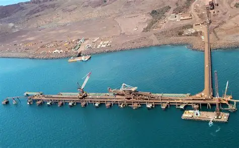
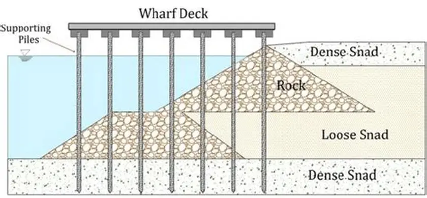
Most jetties consist of an elevated deck supported on piles or columns founded below water level (Figure 1). The deck may comprise reinforced concrete, structural steel, or composite construction, depending on functional and durability requirements. The supporting piles transfer vertical loads into the ground while also resisting horizontal forces from wind, waves, berthing impacts, and thermal movement.
Load paths differ from those in conventional buildings. Vertical loads transfer through the deck into piles primarily as axial force. Environmental actions introduce significant bending and shear in piles, often governing design. The structure therefore behaves as a frame or grillage supported by laterally loaded piles rather than a gravity-dominated system.
Understanding load transfer is essential at an early stage. Assumptions made during conceptual design strongly influence pile sizing, spacing, and global stiffness. Incorrect assumptions often lead to excessive pile demand or unrealistic boundary conditions in analysis models.
Basis of Design and Governing Standards
Structural verification follows the principles of EN 1990, which establishes reliability formats, design situations, and load combinations. Marine structures typically involve persistent and transient design situations, with accidental situations also relevant where vessel impact or abnormal loading may occur.
Actions on jetties derive primarily from EN 1991, supplemented where necessary by marine-specific guidance. Wind actions follow EN 1991-1-4, while imposed loads follow EN 1991-1-1. Snow actions may apply to deck surfaces in cold climates under EN 1991-1-3.
Material resistance follows the relevant Eurocodes. Reinforced concrete elements follow EN 1992-1-1, steel elements follow EN 1993-1-1, and composite decks may follow EN 1994. Geotechnical verification of piles and foundations follows EN 1997-1.
Durability requirements link directly to EN 1992-1-1, Section 4, and corresponding provisions in steel design standards.
Actions on Jetties and Marine Platforms
Permanent Actions
Permanent actions include self-weight of the deck, beams, piles, parapets, services, and fixed equipment. These loads establish baseline axial forces in piles and influence second-order effects in slender elements.
For reinforced concrete decks, self-weight often dominates permanent loading. For steel or composite decks, additional permanent loads may arise from protective systems and corrosion allowances.
Permanent actions should reflect realistic long-term conditions rather than temporary construction states.
Imposed Loads
Imposed loads depend on function. Pedestrian jetties follow category A or C loads under EN 1991-1-1, while vehicle jetties may require bespoke loading models. Loading from cranes, forklifts, or mooring equipment often governs local deck design.
Where load arrangements deviate from standard categories, EN 1991-1-1, Clause 3.3 permits project-specific loading defined by the designer. These loads must reflect realistic operational scenarios.
Imposed loads also influence fatigue performance where cyclic loading occurs.
Wind Actions
Wind actions follow EN 1991-1-4, with exposure often corresponding to open terrain or coastal conditions. Reduced shielding increases wind pressure compared to inland sites. Deck elevation above water increases wind exposure further.
Wind acts on the deck soffit, parapets, superstructure, and any mounted equipment. These loads introduce horizontal forces and overturning moments that must be resisted primarily by piles.
Dynamic wind effects rarely govern static design but may influence serviceability where deck vibrations affect comfort or equipment performance.
Wave and Current Actions
While Eurocodes do not explicitly address wave loading, these actions often dominate jetty design. Designers typically adopt recognised marine engineering formulations consistent with EN 1990, Clause 1.5, which permits the use of complementary standards.
Wave and current forces act directly on piles, inducing bending and shear. These forces vary with water depth, pile diameter, and wave characteristics. Combined wave and current effects often govern pile demand.
Ignoring hydrodynamic actions frequently leads to unconservative pile design.
Accidental Actions
Accidental actions may include vessel impact, abnormal berthing loads, or loss of a structural element. EN 1990, Clause 3.2 defines accidental design situations requiring reduced partial factors.
Berthing and mooring forces often control local design of fenders and supporting members. While specialised guidance exists, the structural system must demonstrate adequate robustness against localised damage.
Global Structural Analysis
Jetty structures often require three-dimensional analysis due to asymmetric loading and pile behaviour. Global analysis must capture the interaction between deck stiffness and pile response.
Piles should not be assumed fully fixed at the seabed unless justified by geotechnical data. EN 1997-1, Clause 7.3 emphasises realistic modelling of soil–structure interaction. Flexible pile head conditions often increase bending moments significantly.
Second-order effects may become relevant for slender piles subjected to combined axial load and lateral bending. EN 1993-1-1, Clause 5.2, and equivalent concrete provisions require consideration where deformations influence internal forces.
Load combinations follow EN 1990, with environmental actions often governing ultimate limit states.
Deck Design and Verification
The deck structure distributes imposed loads to supporting piles. Reinforced concrete decks typically behave as slabs spanning between beams or pile caps. Steel decks may behave as grillages.
Verification under EN 1992-1-1 or EN 1993-1-1 addresses bending, shear, punching, and serviceability. Crack control becomes particularly important in marine environments to limit durability risks.
Deflection limits should consider functional requirements rather than comfort alone. Excessive deflection may damage services, utilities, or bearings.
Pile Design and Verification
Piles form the primary load-resisting elements. They experience combined axial load, bending, and shear. Design must address both structural resistance and geotechnical capacity.
Structural verification follows EN 1992-1-1 for concrete piles or EN 1993-1-1 for steel piles. Combined action checks must consider interaction between axial force and bending.
Geotechnical verification follows EN 1997-1, addressing axial resistance, lateral resistance, and serviceability displacement. Lateral deflection often governs design rather than ultimate capacity.
Ignoring serviceability displacement may lead to unacceptable deck movement or structural distress.
Durability and Exposure Conditions
Durability governs long-term performance. Marine environments expose structures to chloride ingress, corrosion, freeze–thaw action, and abrasion.
Exposure classes under EN 1992-1-1, Table 4.1 often include XS and XF categories. These require increased concrete cover, crack width control, and appropriate material selection.
Steel elements require corrosion protection systems consistent with exposure severity. Allowances for section loss may be necessary where inspection access remains limited.
Durability considerations must integrate with structural design rather than being treated as a coating issue.
Serviceability and Long-Term Performance
Serviceability checks address deflection, vibration, crack width, and long-term movement. These checks often govern pile stiffness and deck thickness.
Creep and shrinkage in concrete decks influence redistribution of forces over time. EN 1992-1-1, Section 3.1.4, provides guidance on time-dependent effects.
Serviceability verification ensures the structure remains functional throughout its design life, not merely safe against collapse.
Conclusion
The structural design of jetties and marine platforms requires an integrated understanding of environmental actions, load paths, and durability. Unlike conventional buildings, environmental effects often govern behaviour and must be addressed explicitly.
A robust Eurocode-based approach combines realistic global analysis with detailed member verification and durability design. When designers understand how loads transfer through the structure and interact with the environment, jetties can achieve reliable long-term performance under demanding conditions.
Also See: Types of Piles and How to Choose the Right One
Sources & Citations
- EN 1990: Eurocode – Basis of Structural Design
- EN 1991-1-1: Actions on Structures – Densities, Self-weight, and Imposed Loads
- EN 1991-1-4: Actions on Structures – Wind Actions
- EN 1992-1-1: Design of Concrete Structures
- EN 1993-1-1: Design of Steel Structures
- EN 1997-1: Geotechnical Design