This article presents the design of welded connections in steel structures to Eurocode 3 and a worked example on the subject.

Welding is a fundamental process in metal fabrication, involving the joining of two or more pieces of metal by melting their edges and allowing them to fuse together. This technique creates a strong, permanent bond between the materials, which is crucial for various applications across construction, automotive, and manufacturing industries. Welded connections are particularly valued for their strength and ability to create seamless joints, making them ideal for both structural and aesthetic purposes. The process can be executed using various methods, such as arc welding, gas welding, and resistance welding, each suited to specific types of materials and project requirements.
Welded connections play a pivotal role in steel structures, offering the necessary strength and stability to support various loads and stresses. These connections are integral to ensuring the overall integrity and safety of the structure. The design of welded connections is governed by stringent codes and standards to guarantee their performance and reliability. One of the most comprehensive standards for designing steel structures, including welded connections, is Eurocode 3 (EN 1993). This article delves deeply into the fundamentals of welded connections and the principles governing their design according to Eurocode 3, providing a thorough understanding of the topic.
Types of Welded Connections
Welded connections are employed in various forms, each tailored to specific applications in steel construction. Understanding the different types of welded connections is crucial for selecting the appropriate method for a given structural requirement. The primary types of welded connections include:

Fillet Welds: Fillet welds are the most common type of weld used in steel construction. They are used to join two surfaces at a right angle or an obtuse angle to each other. Fillet welds are typically employed in lap joints, T-joints, and corner joints. The weld material is deposited in a triangular cross-section along the joint, providing a continuous bond between the surfaces. Fillet welds are favored for their simplicity and versatility.
Butt Welds: Butt welds are used to join two pieces end-to-end in the same plane, creating a smooth and continuous surface. This type of weld is essential in applications where a high degree of strength and a smooth surface finish are required, such as in beam-to-column connections. Butt welds involve preparing the edges of the components to be joined, ensuring proper penetration of the weld material for a strong bond.
Plug and Slot Welds: Plug and slot welds are used to join overlapping plates with holes (plugs) or elongated holes (slots) in one plate filled with weld metal. These welds provide localized bonding and are typically used in situations where a high degree of shear resistance is needed. The weld material is deposited within the holes, creating a solid connection between the plates.
Groove Welds: Groove welds are used in situations where a full penetration weld is required. They involve the preparation of the edges of the components to be joined, allowing for deep penetration of the weld material. Groove welds are essential for applications requiring maximum strength and load-carrying capacity, such as in critical structural connections.
Design Principles of Welded Connections
The design of welded connections according to Eurocode 3 involves several critical steps, each ensuring that the connection meets the required strength and performance criteria. These steps include the determination of weld size and type, calculation of design forces, assessment of weld strength, and verification of compliance with design criteria. Let’s explore these principles in detail:
Determination of Weld Size and Type: The first step in designing a welded connection is to determine the appropriate size and type of weld based on the required strength and the geometry of the connection. Eurocode 3 provides guidelines on the minimum and maximum weld sizes to ensure proper load transfer and avoid weld defects. The choice of weld type—whether fillet, butt, plug, slot, or groove—depends on the specific application and the forces acting on the connection.
Calculation of Design Forces: The next step involves accurately calculating the forces acting on the welded connection. These forces include axial forces, shear forces, and moments. Eurocode 3 specifies the methods for determining these forces, considering the load conditions and the structural configuration. Accurate calculation of design forces is crucial for ensuring the connection can withstand the applied loads without failure.
Assessment of Weld Strength: Once the design forces are determined, the strength of the weld must be assessed based on the type of loading (e.g., static, fatigue) and the material properties. Eurocode 3 provides formulas for calculating the design strength of welds under different loading conditions. This assessment ensures that the weld can safely carry the applied loads without exceeding its capacity.
Check for Compliance with Design Criteria: The final step in the design process is to verify that the welded connection complies with the design criteria set forth in Eurocode 3. This includes checks for strength, ductility, and stability. Compliance with these criteria ensures that the welded connection meets the required performance standards and can withstand the demands of the structural application.
Design Procedures in Eurocode 3
Eurocode 3 provides detailed procedures for designing welded connections, encompassing strength verification, geometrical considerations, and detailing and execution guidelines. These procedures ensure that welded connections are designed to meet the highest standards of safety and performance. Let’s explore these procedures in detail:
Strength Verification: Strength verification is a critical aspect of designing welded connections. For fillet welds, the design shear strength is verified using the formula:
F_{Ed} \le F_{vw,Rd}where F,Ed is the design shear force and fvw,Rd is the design shear strength of the weld material. This verification ensures that the fillet weld can safely carry the applied shear force without failure.
For butt welds, the verification involves checking the tensile strength using:
F_{b,Ed} \le f_{b,u}where Fbw,Ed is the design tensile force and fu,d is the design tensile strength of the weld material. This check ensures that the butt weld can withstand the applied tensile force without exceeding its capacity.
Geometrical Considerations: Eurocode 3 specifies the minimum and maximum dimensions for welds to ensure proper load transfer and avoid weld defects. These geometrical considerations include the weld size, length, and spacing. Proper geometrical design is crucial for ensuring the strength and durability of the welded connection.
Detailing and Execution: Proper detailing and execution of welds are essential for ensuring the designed performance of the welded connection. Eurocode 3 provides guidelines for weld quality, inspection, and testing. These guidelines ensure that the welds are executed to the highest standards, minimizing the risk of defects and ensuring the structural integrity of the connection.
Factors Influencing Welded Connection Design
Several factors influence the design of welded connections, including material properties, load conditions, environmental factors, and fabrication and execution practices. Understanding these factors is crucial for designing welded connections that meet the required performance standards. Let’s explore these factors in detail:
Material Properties: The properties of the steel and welding consumables used affect the strength and performance of the welded connection. Material properties such as yield strength, tensile strength, and ductility play a significant role in determining the capacity of the weld. Eurocode 3 provides guidelines for selecting appropriate materials to ensure the designed performance of the welded connection.
Load Conditions: The type and magnitude of loads acting on the welded connection significantly influence the design. These loads can include static loads, dynamic loads, and cyclic loads. Eurocode 3 specifies the methods for calculating the design forces for different load conditions, ensuring that the welded connection can safely carry the applied loads without failure.
Environmental Factors: Environmental factors such as temperature, corrosion, and exposure to chemicals can impact the performance of welded connections. Proper consideration of these factors is essential for ensuring the durability and longevity of the welded connection. Eurocode 3 provides guidelines for designing welded connections for various environmental conditions, including the selection of appropriate materials and protective coatings.
Fabrication and Execution: Proper fabrication and execution practices are essential for ensuring the designed strength and durability of welded connections. This includes proper preparation of the surfaces to be welded, selection of appropriate welding procedures, and thorough inspection and testing of the welds. Eurocode 3 provides guidelines for ensuring high-quality fabrication and execution practices, minimizing the risk of defects and ensuring the structural integrity of the welded connection.
Worked Example
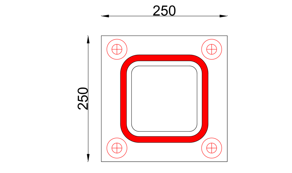
A 150x150x10mm SHS is required as a column in a multi-storey steel building. Assuming a base plate of size 250 x 250 x 20mm is provided (See Figure). Assuming all shear forces are being resisted by the welds alone, verify the capacity of the welds to resist an applied shear-force of 400kN. Steel grade is S275, and welding side is 10mm.
Throat of Weld
a=0.7071t =0.7071\times10=7mm
Design Weld Resistance
To determine the weld resistance, we must first the design weld strength, and then estimate the resistance per metre length. The weld resistance for the connection is then the resistance per unit length multiplied by the length of the weld which is basically the perimeter of the steel section as shown in figure above.
The design weld strength and resistance per unit length is given as:
f_{v,wd}=\frac{f_u}{\sqrt 3 \beta \gamma_{M2}} =\frac{430}{\sqrt 3 \times 0.85\times 1.25} =233.65Mpa
F_{W,Ed}=f_{v,wd}a =233.65\times7= 1.64kN/mmSince it is assumed that the weld is done right about the perimeter of the connection, therefore, the total weld resistance mobilised is given as
=F_{W,Ed}\times L =1.64\times (4\times150)= 984kN(V_{Ed} =450kN) < (F_{W,Ed}=984kN)Since the applied shear force is less than weld resistance of the connection, the provided weld is adequate.
See: Simple Connections in Multi-Storey Frames
Conclusion
Welded connections are fundamental to the integrity and performance of steel structures. Eurocode 3 provides a robust framework for designing these connections, ensuring they meet the required strength, durability, and performance criteria. By following the guidelines outlined in Eurocode 3, engineers can design safe, efficient, and durable welded connections for a wide range of steel structures. Understanding the principles and procedures of welded connection design is essential for ensuring the safety and reliability of steel structures in various applications.